1
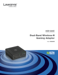
Wireless Gaming
Router II
WL-309
Full Manual
WL-309 Wireless Gaming router II
Full Manual
INTRODUCTION............................................................................................ 4
FEATURES & BENEFITS .......................................................................................5
PACKAGE CONTENTS ..........................................................................................6
SAFETY GUIDELINES ..........................................................................................6
PRODUCT LAYOUT ..........................................................................................7
BACK LABEL
..........................................................................................8
SYSTEM REQUIREMENTS.................................................................................... 10
1
UNDERSTANDING THE HARDWARE...................................................... 11
HARDWARE INSTALLATION ................................................................................. 11
IP ADDRESS CONFIGURATION ............................................................................. 12
2
INTERNET CONNECTION WIZARD........................................................ 13
3 WI-FI PROTECTED SETUP WIZARD.......................................................... 15
ADD A WIRELESS DEVICE .................................................................................. 16
USING THE PIN
........................................................................................ 17
USING THE PUSH BUTTON ................................................................................. 18
4 ADVANCED WEB CONFIGURATION .......................................................... 19
LOGGING IN
........................................................................................ 19
4.1 HOME
........................................................................................ 20
Device.................................................................................................... 20
Wireless ................................................................................................. 20
Logs ...................................................................................................... 22
Stats...................................................................................................... 23
DHCP ..................................................................................................... 24
Firewall .................................................................................................. 25
4.2 BASIC
........................................................................................ 26
Network ................................................................................................. 26
Wireless ................................................................................................. 28
WAN ...................................................................................................... 33
Advanced Wireless................................................................................... 41
Advanced Network................................................................................... 42
4.3 FIREWALL
........................................................................................ 44
Virtual Server.......................................................................................... 44
Special Application................................................................................... 45
Port Forwarding....................................................................................... 46
Access Control ........................................................................................ 47
Website Filter.......................................................................................... 50
Schedules............................................................................................... 51
4.4 ADVANCED SETTINGS ................................................................................. 52
Dynamic DNS.......................................................................................... 52
StreamEngine ......................................................................................... 53
Routing .................................................................................................. 54
MAC Address Filter................................................................................... 55
Firewall Settings ...................................................................................... 56
WISH ..................................................................................................... 60
Inbound Filter ......................................................................................... 62
Bandwidth .................................................... Error! Bookmark not defined.
Users ........................................................... Error! Bookmark not defined.
4.5 TOOLBOX
........................................................................................ 66
WL-309 Wireless Gaming router II
Full Manual
Time Configuration .................................................................................. 66
System Settings ...................................................................................... 67
Firmware................................................................................................ 71
Syslog.................................................................................................... 71
Administrator Settings ............................................................................. 72
APPENDIX A FCC INTERFERENCE STATEMENT ............................................ 74
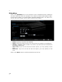
Introduction
The WL-309 is a draft 802.11n compliant device that delivers up to 6x faster
speeds than 802.11g while staying backward compatible with 802.11g and
802.11b devices.
It is not only a Wireless Access Point, which lets you connect to the network
without wires. There's also a built-in 4-port full-duplex 10/100/1000 Gigabit
Switch to connect your wired-Ethernet devices together. The Router function ties
it all together and lets your whole network share a high-speed cable or DSL
Internet connection.
The Access Point built into the Router uses advanced MIMO (Multi-Input, MultiOutput) technology to transmit multiple steams of data in a single wireless
channel. The robust signal travels farther, maintaining wireless connections up to
3 times farther than standard 802.11g, eliminating dead spots and extending
network range.
To protect the data and privacy, the Router can encode all wireless transmissions
with 64/128-bit encryption. It can serve as your network's DHCP Server, has a
powerful SPI firewall to protect your PCs against intruders and most known
Internet attacks, and supports VPN pass-through. The router also provides easy
configuration with the web browser-based configuration utility.
The incredible speed and the fully automatic QoS function of the 802.11n
(draft2.0) Gigabit Router is ideal for media-centric applications like streaming
video, gaming, and VoIP telephony. It is designed to run multiple media-intense
data streams through the network at the same time, with no degradation in
performance.
AGE
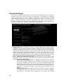
Features & Benefits
Features
High Speed Data Rate Up to
Benefits
Capable of handling heavy data
300Mbps
payloads such as MPEG video
streaming
Concurrent Dual band
(2.4GHz and 5GHz)
Connect your client devices via the
2.4GHz band, while streaming media
on the clean 5GHz band.
IEEE 802.11n draft Compliant
and backward compatible with
802.11b/g
Fully interoperable with IEEE
802.11b/g/n devices
Four built-in 10/100/1000Mbps
Gigabit Switch Ports (AutoCrossover)
Scalability, able to extend your
network
Supports DNS/ DDNS
Lets users assign a fixed host and
domain name to a dynamic Internet IP
address.
Shares single Internet account and
provides a type of firewall by hiding
internal IP addresses for keeping
hacker out
Avoids unallowable users sharing
bandwidth, increases efficiency of the
network
Avoids the attacks of Hackers or
Viruses from Internet
Supports NAT (Network Address
Translation)/NAPT
Hide SSID
Firewall supports Virtual Server
Mapping, DMZ, IP Filter, ICMP
Blocking, SPI
Support 802.1x authenticator,
802.11i (WPA/WPA2, AES), VPN
pass-thru mechanisms
Provide mutual authentication (Client
and dynamic encryption keys to
enhance security
WDS (Wireless Distribution
Make wireless AP and Bridge mode
System)
simultaneously as a wireless repeater
Universal Plug and Play (UPnP™)
Works with most Internet gaming and
instant messaging applications for
automatic Internet access
The filter can be scheduled by days,
Filter Scheduling
hours or minutes for easy management
Real time alert
The detection of a list for Hacker login information
Web configuration
Helps administrators to remotely
configure or manage the Router via
Telnet/Web-browser
AGE
Package Contents
Open the package carefully, and make sure that none of the items listed below
are missing. Do not discard the packing materials; in case of return, the device
must be shipped in its original package.
-
One WL-309 Wireless Gaming router II
One 12V/1.25A Power Adapter
UTP Cable
One CD-ROM with User’s Manual
One Quick Installation Guide
Warranty Card
Safety Guidelines
In order to reduce the risk of fire, electric shock and injury, please adhere to the
following safety guidelines.
-
AGE
Carefully follow the instructions in this manual; also follow all instruction
labels on the device.
Except for the power adapter supplied, the device should not be
connected to any other adapters.
Do not spill liquid of any kind on the device.
Do not place the device on an unstable stand or table. The device may
drop and become damaged.
Do not expose the device to direct sunlight.
Do not place any hot devices close to this device, as they may degrade
or cause damage to the device.
Do not place any heavy objects on top of the device.
Do not use liquid cleaners or aerosol cleaners. Use a soft dry cloth for
cleaning.
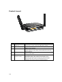
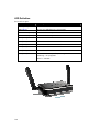
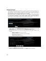
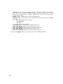
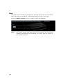
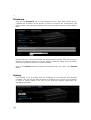
Product Layout
Item
1
AGE
2
Label
LAN Ports
(yellow)
WAN Port (blue)
3
DC Connector
4
USB port
5
WPS (on the top
of the router)
Description
Use an Ethernet cable to connect each port to a
computer on your Local Area Network (LAN).
Use an Ethernet cable to connect this port to your
WAN router/modem.
Use the power cable and connect the adapter to the
power socket on the wall, and the DC inlet into the
DC connector.
The USB port can be used to connect a USB memory
stick or hard disk.
WPS (Wireless Push Button) is used for Wi-Fi
Protected Setup. By pressing this button, the
security settings of the device will automatically
synchronize with other wireless devices on your
network that support Wi-Fi Protected Setup.
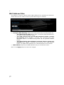
Back label
The back label describes the IP address, login details, SSID, security code and WPS
button functionality.
Button
Description
WPS BUTTON
Press 0-5 seconds for 2.4 GHz WPS mode
Press 5-10 seconds for 5 GHz WPS mode
Press 10 seconds to reset the router
Press 15 Seconds to reset the router to factory
defaults.
AGE
LED Definition
From left to right.
Port
Description
Power (Blue)
Shows the device is turned on.
USB (Blue)
Shows an USB device is connected.
WiFi 2.4 GHz (Blue)
Shows WiFi activity on the 2.4 GHz band.
WiFi 2.4 GHz (Blue)
Shows WiFi activity on the 2.4 GHz band.
WAN (Blue)
Shows the cable is connected.
LAN (Blue)
Shows the cable is connected.
LAN (Blue)
Shows the cable is connected.
LAN (Blue)
Shows the cable is connected.
LAN (Blue)
Shows the cable is connected.
WPS (Blue)
Shows WPS activity after pushing WPS button.
Flashing = In progress
Solid = success
AGE
10
System Requirements
The following are the minimum system requirements in order configure the
device:
-
AGE
10
PC/Notebook
Operating System – Microsoft Windows XP/2000/Vista/Seven
1 Free Ethernet port
Wi-Fi card/USB dongle (802.11 b/g/n) – optional
External xDSL (ADSL) or Cable modem with an Ethernet port (RJ-45)
PC with a web-browser (Internet Explorer, Safari, Firefox, Opera)
Ethernet compatible CAT5 cables
11
-
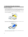
1 Understanding the Hardware
Hardware Installation
You can place the WL-309 on a desk or other flat surface, or you can mount it on
a wall. For optimal performance, place your Wireless Broadband Router in the
center of your office (or your home) in a location that is away from any potential
source of interference, such as a metal wall or microwave oven. This location
must be close to a power connection and your ADSL/Cable modem.
Plug one end of the Ethernet cable into the LAN port of the device and another
end into your PC/Notebook.
Plug one end of another Ethernet cable to the WAN port of the device and the
other end into you cable/DSL modem (Internet).
Insert the DC-outlet of the power adapter into the port labeled “DC-IN” and the
other end into a power socket on the wall.
AGE
11
12
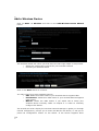
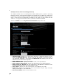
IP Address Configuration
This device can be configured as a Bridge/Router or Access Point. The default IP
address of the device is 192.168.0.1. In order to log into this device, you must first
configure the TCP/IP settings of your PC/Notebook.
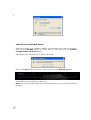
1. In the control panel, double click Network Connections and then double click
on the connection of your Network Interface Card (NIC). You will then see the
following screen.
2. Select Internet Protocol (TCP/IP) and then click on the Properties button.
This will allow you to configure the TCP/IP settings of your PC/Notebook.
Select both [Obtain an IP address automatically] and [Obtain DNS
server address automatically].
3. Click on the OK button to close this window, and once again to close LAN
properties window.
AGE
12
13
2 Internet Connection Wizard
This device offers a quick and simple configuration through the use of a wizard.
This chapter describes how to use the wizard to configure the internet settings.
Please refer to Chapter 6 in order to configure the more advanced features of the
device.
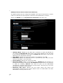
Logging In
To configure the device, open a web browser.
Type http://192.168.0.1 in the address bar and press [Enter].
After connecting to the IP address, the web-browser will display the login page.
Fill in the username and password. The default credentials are shown below:
Username:
Password:
admin
admin
Click on the Wizard button to begin the process.
AGE
13
14
Select your country from the Country list. Select your internet provider. Click
Next.
Depending on the chosen provider, you may need to enter your user name and
password, MAC address or hostname in the following window. After you have
entered the correct information, click Next.
Click APPLY to complete the configuration.
AGE
14
15
3 Wi-Fi Protected Setup Wizard
Wi-Fi Protected Setup is a feature that locks the wireless security settings and
prevents the settings from being changed by any new external registrar using its
PIN. Devices can still be added to the wireless network using Wi-Fi Protected
Setup.
Please refer to Chapter 5 in order to configure the more advanced features of the
device
Logging In
Open a web browser and type in the IP address (default: http://192.168.0.1),
the web-browser will display the login page.
Fill in the username and password. The default credentials are shown below:
Username:
Password:
AGE
15
admin
admin
16
Add a Wireless Device
Click on Basic -> Wireless and click on the Add Wireless Device Wizard
button.
The wireless wizard will inform you that there are two major steps in the process.
o Select the configuration method for your wireless network
o Connect your wireless device
Click on the Next button to continue.
You may select from three available options:
o PIN: Select this radio button if your wireless device supports PIN
o Push Button: Select this radio button if your wireless device supports
push button.
o Manual: Select the radio button if you would like to setup your
wireless device manually. Refer to chapter 5 in order to manually
configure the device.
The wizard will either display the wireless network settings to guide you through
manual configuration, prompt you to enter the PIN for the device, or ask you to
press the configuration button on the device. If the device supports Wi-Fi
AGE
16
17
Protected Setup and has a configuration button, you can add it to the network by
pressing the configuration button on the device and then the on the router within
60 seconds. The status LED on the router will flash three times if the device has
been successfully added to the network.
There are several ways to add a wireless device to your network. Access to the
wireless network is controlled by a registrar. A registrar only allows devices onto
the wireless network if you have entered the PIN, or pressed a special Wi-Fi
Protected Setup button on the device. The router acts as a registrar for the
network, although other devices may act as a registrar as well.
Using the PIN
A PIN is a unique number that can be used to add the router to an existing
network or to create a new network. The default PIN may be printed on the
bottom of the router. For extra security, a new PIN can be generated. You can
restore the default PIN at any time. Only the Administrator ("admin" account) can
change or reset the PIN.
Select the PIN radio button and then click on the Next button.
Specify the PIN and then click on the Connect button.
The wireless device configuration is now complete.
AGE
17
18
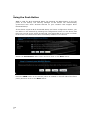
Using the Push Button
WPS is used for Wi-Fi Protected Setup. By pressing the WPS button on the top
panel of the device, the security settings of the device will automatically
synchronize with other wireless devices on your network that support Wi-Fi
Protected Setup
If the device supports Wi-Fi Protected Setup and has a configuration button, you
can add it to the network by pressing the configuration button on the device and
then the one the router within 60 seconds. The status LED on the router will flash
three times if the device has been successfully added to the network.
Select the Push Button radio button and then click on the Next button.
Press the WPS button on the device (which is located on the left side of the front
panel) and then click on the Next button.
AGE
18
19
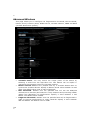
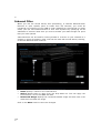
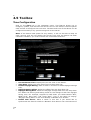
4 Advanced Web Configuration
Logging In
Open a web browser and type in the IP address (default: http://192.168.0.1),
the web-browser will display the login page.
Fill in the username and password. The default credentials are shown below:
Username:
Password:
admin
admin
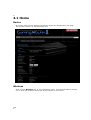
After logging in you will see the graphical user interface (GUI) of the device. The
navigation menu on the top is divided into six main sections:
1.
2.
3.
4.
5.
6.
AGE
19
Home: This shows the basic status of the router.
Wizard: The setup wizard which will guide you through the initial setup.
Basic: This menu includes the network settings, wireless settings and WAN
settings.
Firewall: This menu includes virtual server, special applications, port
forwarding, access control, etc.
Advanced Settings: This menu includes DDNS, the Stream engine, MAC
address filter, web filter etc.
Toolbox: This menu displays the Time zone, Firmware update, Password
settings etc.
20
4.1 Home
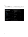
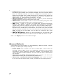
Device
All of your Internet and network connection details are displayed on this page.
The firmware version is also displayed here.
Wireless
Click on the Wireless link in the navigation menu. The wireless section allows
you to view the wireless clients that are connected to the device.
AGE
20
21
-
-
MAC Address: The Ethernet ID (MAC address) of the wireless client.
IP Address: The LAN-side IP address of the client.
Mode: The transmission standard being used by the client. Values are
11a, 11b, 11g, or 11n for 802.11a, 802.11b, 802.11g, or 802.11n
respectively.
Rate: The actual transmission rate of the client in megabits per second.
Signal: This is a relative measure of signal quality. The value is
expressed as a percentage of theoretical best quality. Signal quality can
be reduced by distance, by interference from other radio-frequency
sources (such as cordless telephones or neighboring wireless networks),
and by obstacles between the router and the wireless device.
WISH
The WISH Sessions page displays full details of active local wireless sessions
through your router when WISH has been enabled. A WISH session is a
conversation between a program or application on a wirelessly connected
LAN-side computer and another computer, however connected.
-
Originator: The IP address and, where appropriate, port number of the
computer that originated a network connection.
- Target: The IP address and, where appropriate, port number of the
computer to which a network connection has been made.
- Protocol: The communications protocol used for the conversation.
- State: State for sessions that use the TCP protocol.
o NO: None -- This entry is used as a placeholder for a future
connection that may occur.
o SS: SYN Sent -- One of the systems is attempting to start a
connection.
o EST: Established -- the connection is passing data.
o FW: FIN Wait -- The client system has requested that the connection
be stopped.
o CW: Close Wait -- the server system has requested that the
connection be stopped.
o TW: Time Wait -- Waiting for a short time while a connection that was
in FIN Wait is fully closed.
AGE
21
22
LA: Last ACK -- Waiting for a short time while a connection that was in
Close Wait is fully closed.
o CL: Closed -- The connection is no longer active but the session is
being tracked in case there are any retransmitted packets still pending.
- Priority: The priority given to packets sent wirelessly over this
conversation by the WISH logic. The priorities are:
o BK: Background (least urgent).
o BE: Best Effort.
o VI: Video.
o VO: Voice (most urgent).
o
-
Time Out: The number of seconds of idle time until the router considers
the session terminated. The initial value of Time Out depends on the type
and state of the connection.
o 300 seconds - UDP connections.
o 240 seconds - Reset or closed TCP connections. The connection does
not close instantly so that lingering packets can pass or the connection
can be re-established.
o 7800 seconds - Established or closing TCP connections.
Logs
Click on the Logs link in the navigation menu. The router automatically logs
(records) events of possible interest in its internal memory. If there is not enough
internal memory for all events, logs of older events are deleted, but logs of the
latest events are retained. The Logs option allows you to view the router logs.
You can define what types of events you want to view and the level of events to
view. This router also has external Syslog Server support so you can send the log
files to a computer on your network that is running a Syslog utility.
-
AGE
22
What to View: Select the features of which you would like to view the
logs: Firewall & Security, System, or Router Status.
View Levels: Select the warning levels for the logs: Critical, Warning, or
Informational.
Click on the Apply Log Settings Now to make the new log effective.
23
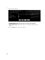
Stats
Click on the Statistics link in the navigation menu. This page displays the
transmitted and received packet statistics of the wired (LAN & WAN) and wireless
interface. Click on the Refresh button to refresh the statistics.
AGE
23
24
DHCP
Click on the DHCP link in the navigation menu. This page displays the routing
details configured for your router.
AGE
24
Local: The IP address and, where appropriate, port number of the local
application.
NAT: The port number of the LAN-side application as viewed by the WAN-side
application.
Internet: The IP address and, where appropriate, port number of the
application on the Internet.
Protocol: The communications protocol used for the conversation.
State: State for sessions that use the TCP protocol.
o NO: None -- This entry is used as a placeholder for a future
connection that may occur.
o SS: SYN Sent -- One of the systems is attempting to start a
connection.
o EST: Established -- the connection is passing data.
o FW: FIN Wait -- The client system has requested that the connection
be stopped.
o CW: Close Wait -- the server system has requested that the
connection be stopped.
o TW: Time Wait -- Waiting for a short time while a connection that was
in FIN Wait is fully closed.
o LA: Last ACK -- Waiting for a short time while a connection that was in
Close Wait is fully closed.
o CL: Closed -- The connection is no longer active but the session is
being tracked in case there are any retransmitted packets still pending.
Priority: The priority given to packets sent wirelessly over this conversation
by the WISH logic. The priorities are:
o BK: Background (least urgent).
o BE: Best Effort.
o VI: Video.
o VO: Voice (most urgent).
Time Out: The number of seconds of idle time until the router considers the
session terminated. The initial value of Time Out depends on the type and
state of the connection.
o 300 seconds - UDP connections.
o 240 seconds - Reset or closed TCP connections. The connection does
not close instantly so that lingering packets can pass or the connection
can be re-established.
o 7800 seconds - Established or closing TCP connections.
25
Firewall
Click on the Firewall link in the navigation menu. This page displays the details
about firewall holes in your router.
AGE
25
26
4.2 BASIC
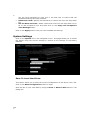
Network
This device can be configured as a Router or a Bridge. Select Router mode if
the WAN port is connected to the Internet. Select Bridge if the device is
connected to a local network downstream from another router.
Bridge Mode
In this mode, the device functions as a bridge between the network on its WAN
port and the devices on its LAN port and those connected to it wirelessly. Select
the Bridge Mode radio button.
WAN Port Mode: Select the Bridge Mode radio button.
Router IP Address: Specify the IP address of this device.
Subnet Mask: Specify the subnet mask for the IP address.
Default Gateway: Specify the IP address of the upstream router.
Primary/Secondary DNS: Specify the IP address of the DNS server.
Click on the Apply button to store these settings.
AGE
26
27
Router Mode
In this mode, the device functions as a NAT router and is connected to the
Internet. Select the Router Mode radio button.
WAN Port Mode: Select the Router Mode radio button.
Router IP Address: Specify the IP address of this device.
Subnet Mask: Specify the subnet mask for the IP address.
Local Domain Name: This entry is optional. Enter a domain name for the
local network. LAN computers will assume this domain name when they get
an address from the router's built in DHCP server. So, for example, if you
enter mynetwork.net here, and you have a LAN side laptop with a name of
mark, that laptop will be known as mark.mynetwork.net. Note, however, the
entered domain name can be overridden by the one obtained from the
router's upstream DHCP server.
Enable DNS Relay: Place a check in this box to enable the DNS relay
feature. When DNS Relay is enabled, the router plays the role of a DNS
server. DNS requests sent to the router are forwarded to the ISP's DNS
server. This provides a constant DNS address that LAN computers can use,
even when the router obtains a different DNS server address from the ISP
upon re-establishing the WAN connection. You should disable DNS relay if you
implement a LAN-side DNS server as a virtual server.
Click on the Apply button to store these settings.
AGE
27
28
Wireless
These options allow you to enable/disable the wireless interface, switch between
the 11n, 11b/g and 11b radio band and channel frequency.
These settings can be made for 2.4Ghz and 5GHZ on the corresponding tabs.
AGE
28
Enable Wireless: Place a check in this box to enable the wireless interface.
It is enabled by default.
Wireless Network Name (SSID): The SSID is a unique named shared
amongst all the points of the wireless network. The SSID must be identical on
all points of the wireless network and cannot exceed 32 characters.
802.11 Mode: Select the IEEE 802.11 mode from the drop-down list. For
example, if you are sure that the wireless network will be using only IEEE
802.11g clients, then it is recommended to select 802.11g only instead of
2.4 GHz B+G, which will reduce the performance of the wireless network.
You may also select Mixed 802.11n, 802.11g and 802.11b. If all of the
wireless devices you want to connect with this router can connect in the same
transmission mode, you can improve performance slightly by choosing the
appropriate "Only" mode. If you have some devices that use a different
transmission mode, choose the appropriate "Mixed" mode.
29
Wireless Channel: Select a channel from the drop-down list. The channels
available are based on the country’s regulation. A wireless network uses
specific channels in the wireless spectrum to handle communication between
clients. Some channels in your area may have interference from other
electronic devices. Choose the clearest channel to help optimize the
performance and coverage of your wireless network.
Transmission Rate: Select a transmission rate from the drop-down list. It is
recommended to use the Best (automatic) option.
Channel Width: Select a channel width from the drop-down list.
Visibility Status: Select Visible or Invisible. This is the SSID broadcast
feature. When this option is set to Visible, your wireless network name is
broadcast to anyone within the range of your signal. If you're not using
encryption then they could connect to your network. When Invisible mode is
enabled, you must enter the Wireless Network Name (SSID) on the client
manually to connect to the network.
Click on the Apply button to store these settings.
Wireless Security Mode
To protect your privacy this router supports several types of wireless security:
WEP WPA, WPA2, and WPA-Mixed. WEP is the original wireless encryption
standard. WPA provides a higher level of security. The following section describes
the security configuration in detail.
WEP (Wired Equivalent Privacy)
Select the WEP radio button if your wireless network uses WEP encryption. WEP
is an acronym for Wired Equivalent Privacy, and is a security protocol that
provides the same level of security for wireless networks as for a wired network.
WEP is not as secure as WPA encryption. To gain access to a WEP network, you
must know the key. The key is a string of characters that you create. When using
WEP, you must determine the level of encryption. The type of encryption
determines the key length. 128-bit encryption requires a longer key than 64-bit
encryption. Keys are defined by entering in a string in HEX (hexadecimal - using
characters 0-9, A-F) or ASCII (American Standard Code for Information
Interchange - alphanumeric characters) format. ASCII format is provided so you
can enter a string that is easier to remember. The ASCII string is converted to
HEX for use over the network. Four keys can be defined so that you can change
keys easily. A default key is selected for use on the network.
AGE
29
30
WEP Key Length: Select a 64-bit or 128-bit WEP key length from the dropdown list.
WEP Key 1-4: You may enter four different WEP keys.
Default WEP Key: You may use up to four different keys for four different
networks. Select the current key that will be used.
Authentication: Select Open, or Shared Key. Authentication method from
the drop-down list. An open system allows any client to authenticate as long
as it conforms to any MAC address filter policies that may have been set. All
authentication packets are transmitted without encryption. Shared Key sends
an unencrypted challenge text string to any device attempting to
communicate with the AP. The device requesting authentication encrypts the
challenge text and sends it back to the access point. If the challenge text is
encrypted correctly, the access point allows the requesting device to
authenticate. It is recommended to select Auto if you are not sure which
authentication type is used.
Click on the Apply button to store these settings.
WPA Personal (Wi-Fi Protected Access)
Select the WPA-Personal radio button if your wireless network uses WPA
encryption. WPA (Wi-Fi Protected Access) was designed to improve upon the
security features of WEP (Wired Equivalent Privacy). The technology is designed
to work with existing Wi-Fi products that have been enabled with WEP. WPA
provides improved data encryption through the Temporal Integrity Protocol
(TKIP), which scrambles the keys using a hashing algorithm and by adding an
integrity checking feature which makes sure that keys haven’t been tampered
with.
AGE
30
31
WPA Mode: Select the Auto WPA / WPA2 from the drop-down list.
Cipher Type: Select TKIP and AES as the cipher suite. The encryption
algorithm used to secure the data communication.
o
o
o
TKIP. Use TKIP only. TKIP (Temporal Key Integrity Protocol) provides
per-packet key generation and is based on WEP.
AES. Use AES only. AES (Advanced Encryption Standard) is a very
secure block based encryption. Note that, if the bridge uses the AES
option, the bridge can associate with the access point only if the
access point is also set to use only AES.
TKIP and AES. The bridge negotiates the cipher type with the access
point, and uses AES when available.
Group Key Update Interval: Specify the number of seconds before the
group key used for broadcast and multicast data is changed.
Pre-Shared Key: The key is entered as a pass-phrase of up to 63
alphanumeric characters in ASCII (American Standard Code for Information
Interchange) format at both ends of the wireless connection. It cannot be
shorter than eight characters, although for proper security it needs to be of
ample length and should not be a commonly known phrase. This phrase is
used to generate session keys that are unique for each wireless client.
Click on the Apply button to store these settings.
WPA Enterprise (Wi-Fi Protected Access & 802.1x)
Select the WPA-Enterprise radio button if your wireless network uses WPA
encryption. WPA (Wi-Fi Protected Access) was designed to improve upon the
security features of WEP (Wired Equivalent Privacy). The technology is designed
to work with existing Wi-Fi products that have been enabled with WEP. WPA
provides improved data encryption through the Temporal Integrity Protocol
(TKIP), which scrambles the keys using a hashing algorithm and by adding an
integrity checking feature which makes sure that keys haven’t been tampered
with.
AGE
31
32
This option works with a RADIUS Server to authenticate wireless clients. Wireless
clients should have established the necessary credentials before attempting to
authenticate to the Server through this Gateway. Furthermore, it may be
necessary to configure the RADIUS Server to allow this Gateway to authenticate
users.
WPA Mode: Select the WPA / WPA2 from the drop-down list.
Cipher Type: Select TKIP or AES as the cipher suite. The encryption
algorithm used to secure the data communication.
o
o
o
TKIP. Use TKIP only. TKIP (Temporal Key Integrity Protocol) provides
per-packet key generation and is based on WEP.
AES. Use AES only. AES (Advanced Encryption Standard) is a very
secure block based encryption. Note that, if the bridge uses the AES
option, the bridge can associate with the access point only if the
access point is also set to use only AES.
TKIP and AES. The bridge negotiates the cipher type with the access
point, and uses AES when available.
Group Key Update Interval: Specify the number of seconds before the
group key used for broadcast and multicast data is changed.
Authentication Timeout: Specify the number of minutes after which the
client will be required to re-authenticate.
RADIUS Server IP Address: Specify the IP address of the RADIUS server.
RADIUS Server Port: Specify the port number of the RADIUS server, the
default port is 1812.
RADIUS Server Shared Secret: Specify the pass-phrase that is matched on
the RADIUS Server.
MAC Address Authentication: Place a check in this box if you would like the
user to always authenticate using the same computer.
Optional Backup RADIUS server: This option enables configuration of an
optional second RADIUS server. A second RADIUS server can be used as
backup for the primary RADIUS server. The second RADIUS server is
consulted only when the primary server is not available or not responding.
Click on the Apply button to store these settings.
AGE
32
33
WAN
The device offers several types of WAN connections in order to connect to the
Internet.
-
Static IP Address
Dynamic IP Address
PPPoE
PPTP
Select the type of Internet Connection from the drop-down list.
Static IP Address Configuration
The WAN interface can be configured as Static IP address. In this type of
connection, your ISP provides you with a dedicated IP address (which does not
change as DHCP).
Select Static IP from the My Internet Connection drop-down list.
AGE
33
34
IP Address: Specify the IP address for this device, which is assigned by your
ISP.
Subnet Mask: Specify the subnet mask for this IP address, which is assigned
by your ISP.
Default Gateway: Specify the IP address of the default gateway, which is
assigned by your ISP.
Primary / Secondary DNS Address: Specify the primary and secondary IP
address, which is assigned by your ISP.
MTU: The Maximum Transmission Unit (MTU) is a parameter that determines
the largest packet size (in bytes) that the router will send to the WAN. If LAN
devices send larger packets, the router will break them into smaller packets.
Ideally, you should set this to match the MTU of the connection to your ISP.
Typical values are 1500 bytes for an Ethernet connection and 1492 bytes for a
PPPoE connection. If the router's MTU is set too high, packets will be
fragmented downstream. If the router's MTU is set too low, the router will
fragment packets unnecessarily and in extreme cases may be unable to
establish some connections. In either case, network performance can suffer.
MAC Address: If you need to change the MAC address of the router's WANside Ethernet interface, either type in an alternate MAC address (for example,
the MAC address of the router initially connected to the ISP) or click on Clone
Your PCs MAC Address.
Click on the Apply button to store these settings. DHCP Connection (Dynamic IP
Address)
AGE
34
35
Dynamic IP Address (DHCP) Configuration
The WAN interface can be configured as a DHCP Client in which the ISP provides
the IP address to the device. This is also known as Dynamic IP.
Select the Dynamic IP (DHCP) from the My Internet Connection drop-down
list.
AGE
35
Host Name: Specify a host name to define your system or connection.
Use Unicasting: This option is normally turned off, and should remain off as
long as the WAN-side DHCP server correctly provides an IP address to the
router. However, if the router cannot obtain an IP address from the DHCP
server, the DHCP server may be one that works better with unicast responses.
In this case, turn the Unicasting option on, and observe whether the router
can obtain an IP address. In this mode, the router accepts unicast responses
from the DHCP server instead of broadcast responses.
Primary / Secondary DNS Address: Specify the primary and secondary IP
address, which are assigned by your ISP.
MTU: The Maximum Transmission Unit (MTU) is a parameter that determines
the largest packet size (in bytes) that the router will send to the WAN. If LAN
devices send larger packets, the router will break them into smaller packets.
Ideally, you should set this to match the MTU of the connection to your ISP.
Typical values are 1500 bytes for an Ethernet connection and 1492 bytes for a
36
PPPoE connection. If the router's MTU is set too high, packets will be
fragmented downstream. If the router's MTU is set too low, the router will
fragment packets unnecessarily and in extreme cases may be unable to
establish some connections. In either case, network performance can suffer.
MAC Address: If you need to change the MAC address of the router's WANside Ethernet interface, either type in an alternate MAC address (for example,
the MAC address of the router initially connected to the ISP) or click on Clone
Your PCs MAC Address.
Click on the Apply button to store these settings.
AGE
36
37
PPPoE (Point-to-Point Protocol over Ethernet)
The WAN interface can be configured as PPPoE. This type of connection is usually
used for a DSL service and requires a username and password to connect.
Select the PPPoE from the My Internet Connection drop-down list.
AGE
37
Address Mode: PPPoE can be used with a dynamic or static IP address. If
you select the Dynamic IP radio button, then the IP address in the next field
is not required. However, if you select the Static IP radio button, then the IP
address in the next field is required.
User Name: Specify the user name which is provided by your ISP.
Password: Specify the password which is provided by your ISP, and then
verify it once again in the next field.
Service Name: Specify the name of the ISP.
Reconnect Mode: Select a reconnection time: Always on (A connection to
the Internet is always maintained), On demand (A connection to the Internet
is made as needed), Manual: You have to open up the Web-based
management interface and click the Connect button manually any time that
you wish to connect to the Internet.
Maximum Idle Time: Specify the time after which the router will
automatically disconnect the current session when no data-traffic has been
detected for the set period of time.
38
Primary / Secondary DNS Address: Specify the primary and secondary IP
address, which is assigned by your ISP.
MTU: The Maximum Transmission Unit (MTU) is a parameter that determines
the largest packet size (in bytes) that the router will send to the WAN. If LAN
devices send larger packets, the router will break them into smaller packets.
Ideally, you should set this to match the MTU of the connection to your ISP.
Typical values are 1500 bytes for an Ethernet connection and 1492 bytes for a
PPPoE connection. If the router's MTU is set too high, packets will be
fragmented downstream. If the router's MTU is set too low, the router will
fragment packets unnecessarily and in extreme cases may be unable to
establish some connections. In either case, network performance can suffer.
MAC Address: If you need to change the MAC address of the router's WANside Ethernet interface, either type in an alternate MAC address (for example,
the MAC address of the router initially connected to the ISP) or click on Clone
Your PCs MAC Address.
Click on the Apply button to store these settings.
AGE
38
39
PPTP (Point-to-Point Tunneling Protocol)
The WAN interface can be configured as PPTP. PPTP (Point to Point Tunneling
Protocol) uses a virtual private network to connect to your ISP. This method of
connection is primarily used in Europe. This method of connection requires you to
enter a username and password (provided by your ISP) to gain access to the
Internet. The supported authentication protocols are PAP and CHAP.
Select the PPTP from the My Internet Connection drop-down list.
AGE
39
Address Mode: PPTP can be used with a dynamic or static IP address. If you
select the Dynamic IP radio button, then the IIP address in the next field is
not required. However, if you select the Static IP radio button, then the IP
address in the next field is required.
PPTP Address: Specify the IP address
PPTP Subnet Mask: Specify the subnet mask for the IP address.
PPTP Gateway IP Address: Specify the IP address of the PPTP gateway.
PPTP Server IP Address: If the PPTP Server’s IP address is different from
the default gateway, then you may specify it here.
User Name: Specify the user name which is provided by your ISP.
Password: Specify the password which is provided by your ISP, and then
verify it once again in the next field.
Reconnect Mode: Select a reconnection time:
40
Always on: A connection to the Internet is always maintained.
On demand: A connection to the Internet is made as needed.
Manual: You have to open up the Web-based management
interface and click the Connect button manually any time that you
wish to connect to the Internet.
Maximum Idle Time: Specify the time after which the router will
automatically disconnect the current session when no data-traffic has been
detected for the set period of time.
Primary / Secondary DNS Address: Specify the primary and secondary IP
address, which is assigned by your ISP.
MTU: The Maximum Transmission Unit (MTU) is a parameter that determines
the largest packet size (in bytes) that the router will send to the WAN. If LAN
devices send larger packets, the router will break them into smaller packets.
Ideally, you should set this to match the MTU of the connection to your ISP.
Typical values are 1500 bytes for an Ethernet connection and 1492 bytes for a
PPPoE connection. If the router's MTU is set too high, packets will be
fragmented downstream. If the router's MTU is set too low, the router will
fragment packets unnecessarily and in extreme cases may be unable to
establish some connections. In either case, network performance can suffer.
MAC Address: If you need to change the MAC address of the router's WANside Ethernet interface, either type in an alternate MAC address (for example,
the MAC address of the router initially connected to the ISP) or click on Clone
Your PCs MAC Address.
o
o
o
Click on the Apply button to store these settings.
AGE
40
41
Advanced Wireless
This page allows you to configure the fragmentation threshold, RTS threshold,
beacon period, transmit power, DTIM interval, wireless isolation, WMM and WDS
(wireless distribution system).
AGE
41
Transmit Power: You may control the output power of the device by
selecting a value from the drop-down list. This feature can be helpful in
restricting the coverage area of the wireless network.
Beacon Period: Beacons are packets sent by a wireless Access Point to
synchronize wireless devices. Specify a Beacon Period value between 20 and
1000. The default value is set to 100 milliseconds.
RTS Threshold: Packets over the specified size will use the RTS/CTS
mechanism to maintain performance in noisy networks and preventing hidden
nodes from degrading the performance. Specify a value between 1 and
65535. The default value is 2346.
Fragment Threshold: Packets over the specified size will be fragmented in
order to improve performance on noisy networks. Specify a value between
256 and 65535. The default value is 2346.
42
DTIM Interval: A DTIM is a countdown informing clients of the next window
for listening to broadcast and multicast messages. When the wireless Access
Point has buffered broadcast or multicast messages for associated clients, it
sends the next DTIM with a DTIM Interval value. Wireless clients detect the
beacons and awaken to receive the broadcast and multicast messages. The
default value is 1. Valid settings are between 1 and 255.
Wireless Isolation: Place a check in this box in order to prevent associated
wireless clients from communicating with each other.
WMM Enable: Enable WMM in order to help control latency and jitter when
transmitting multimedia content over a wireless connection.
WDS: Place a check in this box to enable WDS (Wireless Distribution
System). When WDS is enabled, this access point functions as a wireless
repeater and is able to wirelessly communicate with other APs via WDS links.
Note that WDS is incompatible with WPA -- both features cannot be used at
the same time. A WDS link is bidirectional; so this AP must know the MAC
Address (creates the WDS link) of the other AP, and the other AP must have a
WDS link back to this AP. Make sure the APs are configured with same
channel number.
WDS AP MAC Address: Specify one-half of the WDS link. The other AP must
also have the MAC address of this AP to create the WDS link back to this AP.
Click on the Apply button to store these changes.
Advanced Network
In this section you can configure the UPnP, WAN Ping, WAN port speed, multicast
streams, and PPPoE pass-through settings.
AGE
42
Enable UPnP: Place a check in this box to enable UPnP. UPnP is short for
Universal Plug and Play, which is a networking architecture that provides
compatibility among networking equipment, software, and peripherals. This
router has optional UPnP capability, and can work with other UPnP devices
and software.
Allow Users to disable Internet Access: Place a check in this box if you
would like to allow to user to terminate the WAN session.
Allow Users to modify Virtual Server Mappings: Place a check in this box
if you would like the users to add, modify, or delete server mapping entries.
43
WAN Port Speed: You may select a WAN port speed from the drop-down
list. It is recommended that you select Auto.
Enable Multicast Streams: Place a check in this box to enable multicast
streams. The router uses the IGMP protocol to support efficient multicasting - transmission of identical content, such as multimedia, from a source to a
number of recipients. This option must be enabled if any applications on the
LAN participate in a multicast group. If you have a multimedia LAN application
that is not receiving content as expected, try enabling this option.
Enable PPPoE Pass Through: Place a check in this box to enable PPPoE
pass-through. This option controls whether LAN computers can act as PPPoE
clients and negotiate the PPP sessions through the router over the WAN
ethernet link. Enabling this option allows LAN computers to act as PPPoE
clients. Disabling this option prevents LAN computers from establishing PPPoE
pass-through connections.
Click on the Apply button to store these settings.
AGE
43
44
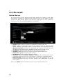
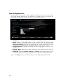
4.3 Firewall
Virtual Server
The Virtual Server option gives Internet users access to services on your LAN.
This feature is useful for hosting online services such as FTP, Web, or game
servers. For each Virtual Server, you define a public port on your router for
redirection to an internal LAN IP Address and LAN port.
Enable: Place a check in this box to enable the virtual server rule.
Name: Assign a meaningful name to the virtual server, for example Web
Server. Several well-known types of virtual server are available from the
Application Name drop-down list. Selecting one of these entries fills some of
the remaining parameters with standard values for that type of server.
IP Address: Specify the IP address for the virtual server entry.
Protocol: Specify a protocol or select one from the drop-down list.
Public Port: Specify the public port number.
Private Port: Specify the private port number.
Schedule: Select a schedule, Always, or Never from the drop-down list. If
a schedule does not exist, you may create it in the Tools > Schedule section.
Inbound Filter: Select an inbound filter from the drop-down list. If an
inbound filter does not exist, you may create it from Advanced > Inbound
Filter section.
Click on the Save button to insert the entry into the Virtual Server list.
AGE
44
45
Special Application
An application rule is used to open single or multiple ports on your router when
the router senses data sent to the Internet on a trigger port or port range. An
application rule applies to all computers on your internal network.
Enable: Place a check in this box to enable the special application rule.
Name: Assign a meaningful name to the virtual server, for example Web
Server. Several well-known types of virtual server are available from the
Application Name drop-down list. Selecting one of these entries fills some of
the remaining parameters with standard values for that type of server.
Triggering Ports: Specify the outgoing port range that is used by the
application.
Firewall Ports: Specify the port range that you would like to open for
Internet traffic.
Schedule: Select a schedule, Always, or Never from the drop-down list. If
a schedule does not exist, you may create it in the Tools > Schedule section.
Click on the Save button to insert the entry into the Special Applications list.
AGE
45
46
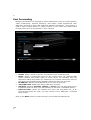
Port Forwarding
Multiple connections are required by some applications, such as internet games,
video conferencing, Internet telephony, and others. These applications have
difficulties working through NAT (Network Address Translation). This section is
used to open multiple ports or a range of ports in your router and redirect data
through those ports to a single PC on your network.
Enable: Place a check in this box to enable the port forwarding rule.
Name: Assign a meaningful name to the virtual server, for example Web
Server. Several well-known types of virtual server are available from the
Application Name drop-down list. Selecting one of these entries fills some of
the remaining parameters with standard values for that type of server.
IP Address: Specify the IP address for the virtual server entry.
TCP/UDP Ports: Specify the TCP or UDP port numbers.
Schedule: Select a schedule, Always, or Never from the drop-down list. If
a schedule does not exist, you may create it in the Tools > Schedule section.
Inbound Filter: Select an inbound filter from the drop-down list. If an
inbound filter does not exist, you may create it from Advanced > Inbound
Filter section.
Click on the Save button to insert the entry into the Port Forwarding list.
AGE
46
47
Access Control
The Access Control section allows you to control access in and out of devices on
your network. Use this feature as Parental Controls to only grant access to
approved sites, limit web access based on time or dates, and/or block access
from applications such as peer-to-peer utilities or games.
When Access Control is disabled, every device on the LAN has unrestricted access
to the Internet. However, if you enable Access Control, Internet access is
restricted for those devices that have an Access Control Policy configured for
them. All other devices have unrestricted access to the Internet.
AGE
47
Place a check in the Enable Access Control check box and then click on the
Add Policy button. This will bring up the Add New Policy wizard.
The wireless wizard will inform you that there are six major steps in the
process.
o Choose a unique name for your policy
o Select a schedule
o Select the machine to which the policy applies
o Select filtering method
o Configure web access logging
Click on the Next button to continue.
Specify a policy name and then click on the Next button to continue.
48
Select a schedule from the drop-down list: Always or Never, or you may
define a new schedule. Click on the Next button to continue.
Select a machine to which the policy applies.
Address Type: Select the IP address or MAC address radio button.
IP Address: If you selected IP address above, then specify the IP address
here.
MAC Address: If you need to change the MAC address of the router's WANside Ethernet interface, either type in an alternate MAC address (for example,
the MAC address of the router initially connected to the ISP) or click on Clone
Your PCs MAC Address.
Click on the OK button to insert the entry into the table.
Click on the Next button to continue.
AGE
48
49
Select a filtering method:
Log Web Access Only: Select this radio but in order to log web access.
Block All Access: Select this radio but in order to block all web access.
Block Some Access: Select this radio but in order to block some web
access.
Click on the Apply button to store the changes.
AGE
49
50
Website Filter
This is a type of parental control feature used to restrict certain websites form
being accessed through your network. These filters can be used for securing and
restricting your network.
Website/URL/Domain: Specify the web address that you would like to
filter. Do not use “http://”
Click on the Save button to store the changes.
AGE
50
51
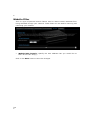
Schedules
Click on the Schedules link in the navigation menu. Schedules can be created for
use with enforcing rules. For example, if you want to restrict web access to MonFri from 3pm to 8pm, you could create a schedule selecting Mon, Tue, Wed, Thu,
and Fri and enter a Start Time of 3pm and End Time of 8pm.
Name: Specify a name for the schedule.
Day(s): Select the days at which you would like the schedule to be effective.
All Day – 24 hrs: Place a check in this box if you would like the schedule to
be active for 24 hours.
Start Time: If you do not use the 24 hours option, you may specify a start
time.
End Time: If you do not use the 24 hours option, you may specify an end
time.
Click on the Save button to add this schedule into the list.
AGE
51
52
4.4 Advanced Settings
Dynamic DNS
The Dynamic DNS feature allows you to host a server (Web, FTP, Game Server,
etc.) using a domain name that you have purchased with your dynamically
assigned IP address. Most broadband Internet Service Providers assign dynamic
(changing) IP addresses. When you use a Dynamic DNS service provider, your
friends can enter your host name to connect to your server, no matter what your
IP address is.
Enable Dynamic DNS: Place a check in this box to enable the DDNS feature.
Service Address: Select a DDNS service provider from the drop-down list.
DynDNS is a free service while TZO offers a 30 day free trial.
Host Name: Specify the website URL.
User Name: Specify the user name for the DDNS service.
Password: Specify the password for the DDNS service and verify it once
again in the next field.
Timeout: Specify the time between periodic updates to the Dynamic DNS, if
the dynamic IP address has not changed. The timeout period is entered in
hours.
Click on the Apply button once you have modified the settings.
AGE
52
53
StreamEngine
The StreamEngine feature helps improve the network performance by prioritizing
applications.
AGE
53
Enable Traffic Shaping: Place a check in the box to enable traffic shaping.
When this option is enabled, the router restricts the flow of outbound traffic
so as not to exceed the WAN uplink bandwidth.
Automatic Uplink Speed. Place a check in this box to enable automatic
uplink speed. When enabled, this option causes the router to automatically
measure the useful uplink bandwidth each time the WAN interface is reestablished (after a reboot, for example).
Measured Uplink Speed: Displays the uplink speed. This is the uplink speed
measured when the WAN interface was last re-established. The value may be
lower than that reported by your ISP as it does not include all of the network
protocol overheads associated with your ISP's network. Typically, this figure
will be between 87% and 91% of the stated uplink speed for xDSL
connections and around 5 kbps lower for cable network connections.
Manual Uplink Speed: Specify an uplink speed or select it from the dropdown list. If Automatic Uplink Speed is disabled, this option allows you to set
54
the uplink speed manually. Uplink speed is the speed at which data can be
transferred from the router to your ISP.
Connection Type: By default, the router automatically determines whether
the underlying connection is an xDSL/Frame-relay network or some other
connection type (such as cable modem or Ethernet), and it displays the result
as Detected xDSL or Frame Relay Network. If you have an unusual network
connection in which you are actually connected via xDSL but for which you
configure either Static or DHCP in the WAN settings, setting this option to
xDSL or Other Frame Relay Network ensures that the router will recognize
that it needs to shape traffic slightly differently in order to give the best
performance. Choosing xDSL or Other Frame Relay Network causes the
measured uplink speed to be reported slightly lower than before on such
connections, but gives much better results.
Click on the Apply button to store these settings.
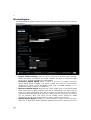
Routing
This section adds a new entry into the routing table.
Enable: Place a check in this box to enable the routing table entry.
Name: Specify a name for the rule.
Destination IP: Specify the destination IP address.
Netmask: Specify the subnet mask for the IP address.
Gateway: Specify the IP address of the gateway.
Metric: Specify the number of routing hops. The route metric is a value from
1 to 16 that indicates the cost of using this route. A value of 1 is the lowest
cost, and 15 is the highest cost. A value of 16 indicates that the route is not
reachable from this router. When trying to reach a particular destination,
computers on your network will select the best route, ignoring unreachable
routes.
Interface: Select the interface from the drop-down list.
Click on the Save button to insert the entry into the Routing table.
AGE
54
55
MAC Address Filter
This feature is used to restrict certain MAC address from accessing the Internet.
These filters can be used for securing and restricting your network.
Configure MAC Filtering: Select one of the options from the drop-down list.
o Turn MAC Filtering OFF: When "OFF" is selected, MAC addresses are
not used to control network access.
o Turn MAC Filtering ON and ALLOW computers listed to access
the network: When "ALLOW" is selected, only computers with MAC
addresses listed in the MAC Filtering Rules list are granted network
access.
o Turn MAC Filtering ON and DENY computers listed to access the
network: When "DENY" is selected, any computer with a MAC address
listed in the MAC Filtering Rules list is refused access to the network.
MAC Address: Specify that MAC address that you would like to filter.
Click on the Apply button to store the changes.
AGE
55
56
Firewall Settings
The device provides a tight firewall by virtue of the way NAT works. Unless you
configure the router to the contrary, the NAT does not respond to unsolicited
incoming requests on any port, thereby making your LAN invisible to Internet
cyber attacks. However, some network applications cannot run with a tight
firewall. Those applications need to selectively open ports in the firewall to
function correctly. The options on this page control several ways of opening the
firewall to address the needs of specific types of applications.
AGE
56
Enable SPI: Place a check in this box to enable SPI. SPI ("stateful packet
inspection" also known as "dynamic packet filtering") helps to prevent cyber
attacks by tracking more state per session. It validates that the traffic passing
through that session conforms to the protocol. When the protocol is TCP, SPI
checks that packet sequence numbers are within the valid range for the
session, discarding those packets that do not have valid sequence numbers.
Whether SPI is enabled or not, the router always tracks TCP connection states
and ensures that each TCP packet's flags are valid for the current state.
TCP / UDP NAT Endpoint Filtering options control how the router's NAT
manages incoming connection requests to ports that are already being used.
Select one of the radio buttons.
o End Point Independent Once a LAN-side application has created a
connection through a specific port, the NAT will forward any incoming
connection requests with the same port to the LAN-side application
regardless of their origin. This is the least restrictive option, giving the
best connectivity and allowing some applications (P2P applications in
particular) to behave almost as if they are directly connected to the
Internet.
o Address Restricted The NAT forwards incoming connection requests
to a LAN-side host only when they come from the same IP address
with which a connection was established. This allows the remote
57
AGE
57
application to send data back through a port different from the one
used when the outgoing session was created.
o Port And Address Restricted The NAT does not forward any
incoming connection requests with the same port address as an
already establish connection.
Note: Some of these options can interact with other port restrictions.
Endpoint Independent Filtering takes priority over inbound filters or
schedules, so it is possible for an incoming session request related to an
outgoing session to enter through a port in spite of an active inbound filter on
that port. However, packets will be rejected as expected when sent to blocked
ports (whether blocked by schedule or by inbound filter) for which there are
no active sessions. Port and Address Restricted Filtering ensures that inbound
filters and schedules work precisely, but prevents some level of connectivity,
and therefore might require the use of port triggers, virtual servers, or port
forwarding to open the ports needed by the application. Address Restricted
Filtering gives a compromise position, which avoids problems when
communicating with certain other types of NAT router (symmetric NATs in
particular) but leaves inbound filters and scheduled access working as
expected.
Enable Port Preservation: Place a check in this box to enable Port
Preservation. NAT Port preservation (on by default) tries to ensure that, when
a LAN host makes an Internet connection, the same LAN port is also used as
the Internet visible port. This ensures best compatibility for internet
communications. Under some circumstances it may be desirable to turn off
this feature.
Enable anti-spoof checking: Place a check in this box to enable anti-spoof
checking. Enabling this option can provide protection from certain kinds of
"spoofing" attacks. However, enable this option with care. With some
modems, the WAN connection may be lost when this option is enabled. In
that case, it may be necessary to change the LAN subnet to something other
than 192.168.0.x (192.168.2.x, for example), to re-establish the WAN
connection.
Enable DMZ Host: Place check in this box to enable DMZ host. DMZ host is a
demilitarized zone used to provide Internet services without sacrificing
unauthorized access to its local private network. Typically, the DMZ host
contains devices accessible to Internet traffic, such as web, FTP, email and
DNS servers.
58
Enabling this option (the default setting) enables single VPN connections to a
remote host. (But, for multiple VPN connections, the appropriate VPN ALG
must be used.) Disabling this option, however, only disables VPN if the
appropriate VPN ALG is also disabled.
Application Layer Gateway (ALG) Configuration: Place a check in
appropriate feature boxes to enable them. . Some protocols and applications
require special handling of the IP payload to make them work with network
address translation (NAT). Each ALG provides special handling for a specific
protocol or application. A number of ALGs for common applications are
enabled by default.
o PPTP: Allows multiple machines on the LAN to connect to their
corporate networks using PPTP protocol. When the PPTP ALG is
enabled, LAN computers can establish PPTP VPN connections either
with the same or with different VPN servers. When the PPTP ALG is
disabled, the router allows VPN operation in a restricted way -- LAN
computers are typically able to establish VPN tunnels to different VPN
Internet servers but not to the same server. The advantage of
disabling the PPTP ALG is to increase VPN performance. Enabling the
PPTP ALG also allows incoming VPN connections to a LAN side VPN
server (refer to Advanced > Virtual_Server).
o IPSec: (VPN) Allows multiple VPN clients to connect to their corporate
networks using IPSec. Some VPN clients support traversal of IPSec
through NAT. This option may interfere with the operation of such VPN
clients. If you are having trouble connecting with your corporate
network, try disabling this option. Check with the system administrator
of your corporate network whether your VPN client supports NAT
traversal.
AGE
58
DMZ IP Address: Specify the IP address of the DMZ host.
Non-UDP/TCP/ICMP LAN Sessions: Place a check in this box to enable
this feature. When a LAN application that uses a protocol other than UDP, TCP,
or ICMP initiates a session to the Internet, the router's NAT can track such a
session, even though it does not recognize the protocol. This feature is useful
because it enables certain applications (most importantly a single VPN
connection to a remote host) without the need for an ALG.
Note: This feature does not apply to the DMZ host (if one is enabled). The
DMZ host always handles these kinds of sessions.
59
o
o
o
o
o
o
o
RTSP: Allows applications that use Real Time Streaming Protocol to
receive streaming media from the internet. QuickTime and Real Player
are some of the common applications using this protocol.
Windows/MSN Messenger: Supports use on LAN computers of
Microsoft Windows Messenger (the Internet messaging client that ships
with Microsoft Windows) and MSN Messenger. The SIP ALG must also
be enabled when the Windows Messenger ALG is enabled.
FTP: Allows FTP clients and servers to transfer data across NAT.
H.323
(Netmeeting):
Allows
H.323
(specifically
Microsoft
Netmeeting) clients to communicate across NAT server.
SIP: Allows devices and applications using VoIP (Voice over IP) to
communicate across NAT. Some VoIP applications and devices have the
ability to discover NAT devices and work around them. This ALG may
interfere with the operation of such devices. If you are having trouble
making VoIP calls, try turning this ALG off.
Wake-On-LAN: This feature enables forwarding of "magic packets"
(that is, specially formatted wake-up packets) from the WAN to a LAN
computer or other device that is "Wake on LAN" (WOL) capable.
MMS: Allows Windows Media Player, using MMS protocol, to receive
streaming media from the internet.
Click on the Apply button to store these settings.
AGE
59
60
WISH
WISH is short for Wireless Intelligent Stream Handling, a technology developed
to enhance your experience of using a wireless network by prioritizing the traffic
of different applications.
AGE
60
Enable WISH: Place a check in this box to enable the WISH feature.
HTTP: Place a check in this box to add HTTP as a classifier. This allows the
device to recognize HTTP transfers for many common audio and video
streams and prioritize them above other traffic. Such streams are frequently
used by digital media players.
Windows Media Center: Place a check in this box to add HTTP as a
classifier. This enables the router to recognize certain audio and video
streams generated by a Windows Media Center PC and to prioritize these
above other traffic. Such streams are used by systems known as Windows
Media Extenders, such as the Xbox 360.
Automatic: Place a check in this box for the device to automatically
configure the classifiers. When enabled, this option causes the router to
automatically attempt to prioritize traffic streams that it doesn't otherwise
recognize, based on the behavior that the streams exhibit. This acts to
deprioritize streams that exhibit bulk transfer characteristics, such as file
transfers, while leaving interactive traffic, such as gaming or VoIP, running at
a normal priority.
Enable: Place a check in this box to enable the WISH rule. A WISH Rule
identifies a specific message flow and assigns a priority to that flow. For most
61
applications, the priority classifiers ensure the right priorities and specific
WISH Rules are not required. WISH supports overlaps between rules. If more
than one rule matches for a specific message flow, the rule with the highest
priority will be used.
Name: Assign a meaningful name to the WISH rule.
Priority: Select a priority from the drop-down list. The four priority message
flows are:
o BK: Background (least urgent).
o BE: Best Effort.
o VI: Video.
o VO: Voice (most urgent).
Protocol: Select a protocol from the drop-down list.
Host 1 IP Range: Specify the IP range for the rule.
Host 1 Port Range: Specify the port range for the rule.
Host 2 IP Range: Specify the IP range for the rule.
Host 2 Port Range: Specify the port range for the rule.
Click on the Apply button to insert the entry into the WISH rules list.
AGE
61
62
Inbound Filter
When you use the Virtual Server, Port Forwarding, or Remote Administration
features to open specific ports to traffic from the Internet, you could be
increasing the exposure of your LAN to cyber attacks from the Internet. In these
cases, you can use Inbound Filters to limit that exposure by specifying the IP
addresses of internet hosts that you trust to access your LAN through the ports
that you have opened.
Inbound Filters can be used for limiting access to a server on your network to a
system or group of systems. Filter rules can be used with Virtual Server, Gaming,
or Remote Administration features.
Name Specify a name for the inbound filter.
Action: Select Allow or Deny from the drop-down list. This will apply the
inbound filter rule on the WAN interface.
Remote IP Range: Specify the remote IP address range and then click in the
check box to enable the range.
Click on the Save button to store the changes.
AGE
62
63
Disk
This page shows information regarding the attached storage devices. File system
type, total space on the device, and available space is shown in the table.
Click the “Safely remove” button, to safely remove the USB disk.
Note:
AGE
63
Only FAT12, FAT16, and FAT32 drives are supported. For information
regarding partitioning and formatting of a drive, see the manual of
your operating system.
64
Share
On this page, the sharing mode can be changed. Choose to share all folders with
all users, or to restrict the sharing of folders. When Sharing-mode is set to
“restrict”, shares can be added and changed.
AGE
64
65
Users
You can add new users and configure user rights for the storage device.
Password: Enter a password for the selected user.
Share Name: Select a shared folder. The Shared folders can be configured
on the “Share” tab.
Access: Select “Read Only” to allow the user to read files in the selected
share. Select “Read/Write” to also allow users to write to the selected share.
AGE
65
66
4.5 Toolbox
Time Configuration
Click on the Time link in the navigation menu. This feature allows you to
configure, update, and maintain the correct time on the device’s internal system
clock as well as configure the time zone. The date and time of the device can be
configured manually or by synchronizing with a time server.
Note: If the device loses power for any reason, it will not be able to keep its
clock running, and will not display the correct time once the device has been
restarted. Therefore, you must re-enter the correct date and time.
AGE
66
Current Router Time: Displays the current time on the device.
Time Zone: Select your time zone from the drop-down list.
Enable Daylight Saving: Place a check in this box to enable daylight savings
time.
Daylight Saving Offset: Select the offset from the drop-down list.
Daylight Saving Date: Select the daylight savings date from the drop-down
list. Select the starting and ending times for the change to and from daylight
saving time. For example, suppose for DST Start you select Month="Oct",
Week="3rd", Day="Sun" and Time="2am". This is the same as saying:
"Daylight saving starts on the third Sunday of October at 2:00 AM."
Enable NTP Server: Place a check in this box if you would like to
synchronize the device’s clock to a Network Time Server over the Internet. If
67
you are using schedules or logs, this is the best way to ensure that the
schedules and logs are kept accurate.
NTP Server Used: Specify the NTP server or select one from the drop-down
list.
Set the Date and Time: Select a date and time from the drop-down list or
do to use computer’s time and date click on the Copy Your Computer’s
Time Settings button.
Click on the Apply button once you have modified the settings.
System Settings
Click on the System link in the navigation menu. This page allows you to reboot
the device using the current settings or restore all the settings to the factory
defaults.
Save To Local Hard Drive
This option allows you to save the current configuration of the device into a file.
Click on the Save Configuration button to begin.
Save the file on your local disk by using the Save or Save to Disk button in the
dialog box.
AGE
67
68
Load From Local Hard Drive
This option allows you to restore a backup configuration from a file to the device.
Click on the Browse button to select the file and then click on Restore
Configuration from a File button.
The system then prompts you to reboot the device.
Click on the OK button to continue. You will then see the Rebooting page.
Please wait while the system is rebooting.
Note: Do no unplug the device during this process as this may cause permanent
damage.
AGE
68
69
Restore To Factory Default
Click on the Restore all Settings to Factory Defaults button. This option
restores all configuration settings back to the settings that were in effect at the
time when the device was shipped from the factory.
Once the dialog box appears, click on the OK button to confirm the action.
Note: The current settings will be lost.
Click on the OK button to continue. You will then see the Rebooting page.
Please wait while the system is rebooting.
Note: Do no unplug the device during this process as this may cause permanent
damage.
Reboot The Device
Click on the Reboot the Device button to reboot the device using its current
settings. Once the dialog box appears, click on the OK button to confirm the
action.
Once the dialog box appears, click on the OK button to confirm the action.
Note: The current settings will be lost.
Click on the OK button to continue. You will then see the Rebooting page.
AGE
69
70
Please wait while the system is rebooting.
Note: Do no unplug the device during this process as this may cause permanent
damage.
AGE
70
71
Firmware
Click on the Firmware link in the navigation menu. This page allows you to
upgrade the firmware of the device in order to improve the functionality and
performance. This page also displays the current firmware version and its release
date.
Ensure that you have downloaded the appropriate firmware from the vendor’s
website. Connect the device to your PC using an Ethernet cable, as the firmware
cannot be upgraded using the wireless interface.
Click on the Browse button to select the firmware and then click on the Upload
button.
Syslog
Logs display a list of events that are triggered on the Ethernet and Wireless
interface. This log can be referred when an unknown error occurs on the system
or when a report needs to be sent to the technical support department for
debugging purposes
AGE
71
72
Enable Logging to a Syslog Server: Place a check in this box to enable
Syslog logging.
Syslog Server IP Address: Specify the IP address of the Syslog server.
Click on the Apply button once you have modified the settings.
Administrator Settings
Admin Password
You can change the password required to log into the broadband router's system
web-based management. By default, the password is: “admin”. Passwords can
contain 0 to 12 alphanumeric characters, and are case sensitive.
Username: Fill in the current username (default: admin).
Password: Enter your new password.
Verify Password: Enter your new password again for verification purposes.
AGE
72
73
System Name
Gateway Name: Name of your router.
Remote Management
The remote management function allows you to configure the Broadband router
from a remote site.
Inactivity Time Out: Time after which you will be automatically logged out of
the web-interface.
HTTPS Server: Enable HTTPS connection for the web-interface.
Enable Remote Management: Select “Enabled” to enable the remote
management function.
Remote Admin Port: The port number of the remote management web
interface.
Click Apply at the top of the screen to save the above configurations.
AGE
73
74
Appendix A FCC Interference
Statement
Federal Communication Commission Interference
Statement
This equipment has been tested and found to comply with the limits for a Class B
digital device, pursuant to Part 15 of the FCC Rules. These limits are designed to
provide reasonable protection against harmful interference in a residential
installation. This equipment generates uses and can radiate radio frequency
energy and, if not installed and used in accordance with the instructions, may
cause harmful interference to radio communications. However, there is no
guarantee that interference will not occur in a particular installation. If this
equipment does cause harmful interference to radio or television reception, which
can be determined by turning the equipment off and on, the user is encouraged
to try to correct the interference by one of the following measures:
Reorient or relocate the receiving antenna.
Increase the separation between the equipment and receiver.
Connect the equipment into an outlet on a circuit different from that to
which the receiver is connected.
Consult the dealer or an experienced radio/TV technician for help.
FCC Caution: Any changes or modifications not expressly approved by the party
responsible for compliance could void the user's authority to operate this
equipment.
This device complies with Part 15 of the FCC Rules. Operation is subject to the
following two conditions: (1) This device may not cause harmful interference, and
(2) this device must accept any interference received, including interference that
may cause undesired operation.
IMPORTANT NOTE:
FCC Radiation Exposure Statement:
This equipment complies with FCC radiation exposure limits set forth for an
uncontrolled environment.
This device complies with FCC RF Exposure limits set forth for an uncontrolled
environment, under 47 CFR 2.1093 paragraph (d)(2).
This transmitter must not be co-located or operating in conjunction with any
other antenna or transmitter.
AGE
74