1
BAR CODE
Programming Menu
V3.8 a
Notice
The manufacturer shall not be liable for technical
or editorial errors or omissions contained herein;
nor for incidental or consequential damages in
connection with the furnishing,performance or use
of use the publication.
Contents
Chapter 1
1.1
1.2
1.3
1.4
1.5
Notice .......................................................
Introduction ...........................................
Codes Read ...........................................
Installation ..............................................
Pin Assignment ......................................
Chapter 2
2.1
2.2
2.3
2.4
Description
Configuration - General
Flow Chart .............................................
Loop of Programming ...........................
Factory Default Settings ........................
Main Page of Configuration...................
Chapter 3
3
4
4
4
6
8
9
9
10
Interface and Reading Mode
Selection
3.1 Interface Selection ................................. 11
3.2 Memory Function .................................... 11
3.3 Reading Mode Selection ........................ 12
Chapter 4
4.1
4.2
4.3
4.4
Communication Parameters
RS232 Mode Parameters ......................
Keyboard Wedge Mode Parameters.....
Output Characters Parameters .............
Wand Emulation Mode Parameters......
Chapter 5
13
15
17
19
Bar Codes & Others
5.1 Symbologies Selection .........................
5.2 UPC/EAN/JAN Parameters ...................
5.3 Code 39 Parameters .............................
5.4 Code 128 Parameters ...........................
5.5 Interleave 25 Parameters ......................
5.6 Industrial 25 Parameters .......................
5.7 Matrix 25 Parameters ............................
5.8 CODABAR/NW7 Parameters ...............
5.9 Code 93 Parameters .............................
5.10 Code 11 Parameters .............................
5.11 MSI/PLESSEY Code Parameters .........
1
20
24
26
28
30
32
34
36
38
40
42
5.12 Code 2 of 6 Parameters ......................... 44
5.13 LCD 25 Parameters ............................. 46
5.14 Telepen Parameters ............................. 48
5.15 GS1 DataBar (RSS Code) ........................50
Chapter 6
Miscellaneous Parameters
6.1 Language Selection .............................. 52
6.2 Bar Code ID .......................................... 54
6.3 Reading Level ........................................ 57
6.4 Accuracy
............................................... 57
6.5 Buzzer Beep Tone ................................. 57
6.6 LED Control .......................................... 57
6.7 Same Code Delay Reading lnterval ...... 58
6.8 Notebook Function ................................ 58
6.9 Reverse Output Characters .................. 59
6.10 Set Up Deletion ...................................... 59
6.11 Set Up Insertion ................................... 62
6.12 Set Up IR Sensor ................................... 65
Appendix
A.
B.
C.
Decimal Value Tables ............................ 67
ASCII Tables .......................................... 68
Function Key Tables .............................. 72
2
Chapter 1 Description
1.1 General
Thank you for purchasing this barcode scanner with
an advanced and versatile decoder.The decoder
works with variety of barcode types,reading devices,
and computer interfaces.It discriminates over twenty
different symbologies automatically.
This menu provides an easy way to configure the
decoding options and interface selections by scanning bar codes listed in the menu.
FCC Approval
This device had been tested in accordance with the procedures and in compliance with Part 15 Subpart B of FCC
Rules. And keeps all requirments according ANSI C63.4 &
FCC Part 15 B Regulation and CISPR22 Class B.
CE Standards
The CE mark as shown here indicates this product had
been tested in accordance with the procedures given in
European Council Directive 2004/108/EC and confirmed to
comply with the Europe Standard EN55022:2006:Class B,
EN 55024:1998+A1:2001+A2:2003,IEC61000-3-2:2006,
IEC61000-3-3:1995+A1:2005,IEC61000-4-2:2001,
IEC61000-4-3:2006,IEC61000-4-4:2004,IEC61000-4-5:
2006,IEC61000-4-6:2001,IEC61000-4-8:2001,IEC61000-411:2004.
LEGISLATION AND WEEE SYMBOL
This marking shown on the product or its literature,
indicates that it should not be disposed with other
households wastes at the end of its working life.To
prevent possible harm to the environment or human healthy from uncontrolled waste disposal,
please separate this from other types of wastes and
recyle it responsibly to promote the sustainable reuse of material resources.
Household users should contact either the retailer
where they purchased this product,or their local
government office,for details of wher and how they
can take this item fore environm entally safe
recycling.Business users should contact their supplier and check the terms and conditions of the purchase
3
1.2
Introduction
The Decoder is an advanced and versatile
decoding facility for barcoding systems .It works
with variety of bar code types, reading devices,
and computer interfaces. It discriminates about
twenty different symbologies automatically.
This menu provide an easy way to config the
decoding options and interface selections by
scanning bar codes listed in the menu.
1.3 Codes Read
. Codes Read
ALL UPC/EAN/JAN , Code 39, Code 39 Full ASCII,
Code 128, Interleave 25, Industrial 25, Matrix 25,
CODABAR/NW7, Code 11, MSI/PLESSEY, Code
93, China Postage, Code32/Italian Pharmacy
Others available upon request.
1.4 Installation
Unpacking –
Remove the scanner from its packing and check it
for damage. If the scanner was defected in transit,
please contact your vendor immediately. Be sure
that you keep the packing with all accessories
contains in the package for your returning of
service.
Connecting the scanner –
Keyboard wedge/RS-232C/USB:
Connect the 10-pins RS-45 male connector into
the bottom of the scanner and you will hear a
“click” when the connection is made.
4
Power supply for RS-232C scanner–
There are 3 ways to supplying the power, use external +5V power supply, use optional power cable
(KBDC) which taking the power from KB wedge or
if the host supports +5V power from pin 9.
Installing the scanner to the Host System –
1. Turn off the host system.
2. Connect the power if needed.
3. Connect to the proper port on the host system.
4. Turn on the host system.
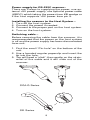
Switching cable –
Before removing the cable from the scanner, it is
recommended that the power on the host system
is off and the power supply has been disconnected
from unit.
1. Find the small “Pin-hole” on the bottom of the
unit.
2. Use a bended regular paperclip and insert the
tip into the hole.
3. You will head a “click”, then gentle on the strainrelief of the cable and it will slide out of the
scanner.
SG/LG Series
SD Series
5
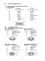
1.5 Pin Assignment
A> Input Port for Mini Decoder
DB 9 Male
Pin No.
Wand /
CCD /
Slot Reader
Laser Scanner
1
N.C.
S.O.S.
2
DATA
DATA
3
N.C.
N.C.
4
N.C.
N.C.
5
N.C.
TRIGGER
6
N.C.
P. E.
7
GND
GND
8
SHIELD
SHIELD
9
+5V
+5V
1
5
6
9
B> Output Port
1. PC Keyboard Output
DIN 5 MALE
DIN 5 FEMALE
Pin No. Function
Pin No. Function
1
HOST CLK
1
KB CLK
2
HOST DATA
2
KB DATA
4
GND
4
GND
5
Vcc(+5V)
5
Vcc(+5V)
1
3
1
3
5
4
5
4
2
2
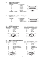
MiniDIN 6 MALE
Pin No. Function
1
HOST DATA
3
GND
4
Vcc
5
HOST CLK
MiniDIN 6 FEMALE
Pin No. Function
1
KB DATA
3
GND
4
Vcc
5
KB CLK
5
3
6
4
6
4
5
3
1
2
2
1
6
2.
RS-232 Output
DB 9 Female
Pin No.
Function
5
2
TXD
3
RXD
5
GND
9
7
CTS
8
RTS
Power Lead
Vcc (+5V)
3.
WAND Emulation Output
DB 9 Female
Pin No.
Function
2
DATA
7
GND
9
Vcc (+5V)
4. ADB Interface
MiniDIN 4 MALE
Pin No. Function
1
ADB
3
Vcc
4
GND
1
6
5
1
9
6
MiniDIN 4 FEMALE
Pin No. Function
1
ADB
3
Vcc
4
GND
3
4
4
3
1
2
2
1
5. NEC 9801 Interface
MiniDIN 8 MALE
Pin No. Function
1
RST
2
GND
3
HOST RDY
4
HOST DATA
5
RTY
8
+5V
6
3
1
7
4
MiniDIN 8 FEMALE
Pin No. Function
1
RST
3
GND
4
KB RDY
5
KB DATA
4
RTY
5
+5V
7
8
5
2
8
5
2
7
4
6
3
1
Chapter 2 Configuration - General
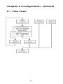
2.1 Flow Chart
8
2.2
Loop of Programming
The philosophy of programming parameters has
been shown on the flow chart of 2.1. Basically user
should
1.Scan Start of Configuration.
2.Scan all necessary labels for parameters that meet
applications.
3.Scan End of Configuration to end the programming.
4.To permanently save the settings you programmed
,just scan label for Save Parameters.
5.To go back to the Default Settings,just scan label
for Set All Defaults.
2.3
Factory Default Settings
The factory default settings are shown with <> and
bold in the following sections.You can make your
own settings by following the procedures in this
manual.If you want to save the settings permanently
,you should scan the label of "Save Parameters" in
chapter 2.4,otherwise the settings will not be saved
after the decoder power is off,and all settings will
go back to previous settings.
By scanning "Set All Default" label,the settings will
go back to the factory default settings.
9
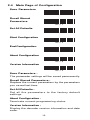
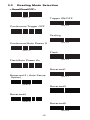
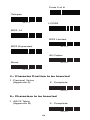
2.4 Main Page of Configuration
Save Parameters
%$ + / 0
Recall Stored
Parameters
%$ + / 1
Set All Defaults
%$ + / 2
Start Configuration
%$ + / 3
End Configuration
%$ + / 4
Abort Configuration
%$ + / 6
Version Information
%$ + / 5
Save Parameters The parameter settings will be saved permanently.
Recall Stored Parameters Replace the current parameters by the parameters
you saved last time.
Set All Defaults Set all the parameters to the factory default
settings.
Abort Configuration Terminate current programming status.
Version Information Display the decoder version information and date
code.
10
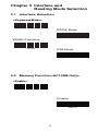
Chapter 3 Interface and
Reading Mode Selection
3.1 Interface Selection
<Keyboard Mode>
%0 0 U0
RS232 Mode
%0 0 U8
WAND Emulation
%0 0 M2
USB Mode
%0 XO8
3.2 Memory Function<HC102M Only>
<Enable>
%0 XI 2
Disable
%0 XI 0
11
3.3
Reading Mode Selection
<Good Read OFF>
%0 2 7 1
Trigger ON/OFF
%0 2 7 0
Continuous/Trigger OFF
%0 2 7 2
Testing
%0 2 7 5
Continuous/Auto Power On
%0 2 7 3
Flash
%0 2 7 4
Flash/Auto Power On
%0 2 7 6
Reserved1
Reserved 2 ( Auto Sense
Option)
%0 2 7 7
%0 9 F8
Reserved3
%0 9 F9
Reserved4
%0 9 FA
Reserved5
%0 9 FB
12
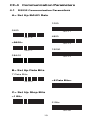
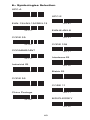
Ch.4 Communication Parameters
4.1 RS232 Communication Parameters
A> Set Up BAUD Rate
1200
2400
%0 Y7 1
4800
%0 Y7 2
<9600>
%0 Y7 3
19200
%0 Y7 7
38400
%0 Y7 4
%0 Y7 5
B> Set Up Data Bits
7 Data Bits
<8 Data Bits>
%0 Y8 0
%0 Y8 8
C> Set Up Stop Bits
<1 Bit>
2 Bits
%0 YO8
%0 YO0
13
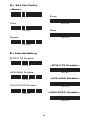
D> Set Up Parity
<None>
Even
%0 YN7
Odd
%0 YN2
Mark
%0 YN3
Space
%0 YN1
%0 YN0
E> Handshaking
RTS/CTS Enable
<RTS/CTS Disable>
%0 1 8 8
ACK/NAK Enable
%0 1 8 0
<ACK/NAK Disable>
%0 1 4 4
XON/XOFF Enable
%0 1 4 0
<XON/XOFF Disable>
%0 3 K4
%0 3 K0
14
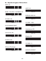
4.2 Keyboard Wedge Mode Parameters
A> Terminal Type
<IBM PC/AT, PS/2>
IBM PC/XT
%0 ZF0
IBM PS/2 25, 30
%0 ZF1
NEC 9800
%0 ZF2
Apple Desktop Bus(ADB)
%0 ZF3
IBM 5550
%0 ZF4
IBM 122 Key (1)
%0 ZF5
IBM 102 Key
%0 ZF6
IBM 122 Key (2)
%0 ZF7
Reserved 1
%0 ZF8
Reserved 2
%0 ZF9
Reserved 3
%0 ZFA
Reserved 4
%0 ZFB
Reserved 5
%0 ZFC
%0 ZFD
15
B> Upper/Lower Case
<No Change>
%0 3 3 0
Upper Case
%0 3 3 1
Lower Case
%0 3 3 2
C> Capslock Detection
Enable
%0 X8 8
<Disable>
%0 X8 0
D> Send Character by ALT Method
Enable
%0 3 O8
<Disable>
E>Select Numerical Pad
ON
%0 3 O0
%0 1 K4
<OFF>
%0 1 K0
16
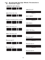
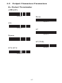
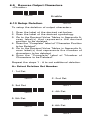
4.3 Output Characters Parameters
A> Select Terminator
<CR+LF>
%7 S2 +
None
%7 S7 +
CR
%7 S0 +
LF
%7 S1 +
Space
%7 S4 +
HT(TAB)
%7 S3 +
STX-ETX
%7 S5 +
17
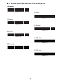
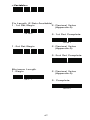
B> Time-out Between Characters
<0 ms>
%0 0 7 0
5 ms
%0 0 7 1
10 ms
%0 0 7 2
25 ms
%0 0 7 3
50 ms
%0 0 7 4
100 ms
%0 0 7 5
200 ms
%0 0 7 6
300 ms
%0 0 7 7
18
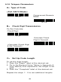
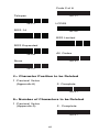
4.4 Wand Emulation Mode Parameters
A> TTL Level Representation
<Bar Equals High>
%0 2 K4
Bar Equals Low
%0 2 K0
B> Scan Speed Selection
<Fast>
%0 2 8 8
Slow
%0 2 8 0
C> Output Format Selection
<Output as Code 39>
%0 2 O8
Output as Code 39
Full ASCII
%0 2 O0
Output as Original
Code Format
%0 XK4
19
Ch.5 Bar Codes & Others
5.1 Symbologies Selection
UPC-A <ON>
OFF
%0 A4 4
UPC-E <ON>
%0 A4 0
OFF
%0 BO8
EAN-13/JAN-13/ISBN-13
<ON>
%0 BO0
OFF
%0 A2 2
EAN-8/JAN-8 <ON>
%0 A2 0
OFF
%0 A1 1
CODE 39 <ON>
%0 A1 0
OFF
%0 EO8
CODE 128 <ON>
%0 EO0
OFF
%0 FO8
CODABAR/NW7 <ON>
%0 FO0
OFF
%0 J O8
%0 J O0
20
Interleave 25 <ON>
OFF
%0 GO8
Industrial 25 ON
%0 GO0
<OFF>
%0 HO8
Matrix 25 ON
%0 HO0
<OFF>
%0 I O8
CODE 93 ON
%0 I O0
<OFF>
%0 KO8
CODE 11 ON
%0 KO0
<OFF>
%0 L O8
China Postage ON
%0 L O0
<OFF>
%0 MO8
MSI/PLESSEY ON
%0 MO0
<OFF>
%0 NO8
%0 NO0
21
Code 2 of 6 ON
<OFF>
%0 PO8
%0 PO0
LCD25 ON
<OFF>
%0 QO8
Telepen ON
%0 QO0
<OFF>
%0 TO8
Reserved5 ON
%0 TO0
<OFF>
%0 RO8
%0 RO0
Reserved6 ON
<OFF>
%0 SO8
%0 SO0
22
GS1 DataBar Omnidirectional ON
%0 UO8
<OFF>
GS1 DataBar Limited ON
%0 VO8
%0 UO0
<OFF>
GS1 DataBar Expanded ON
%0 WO8
%0 VO0
<OFF>
%0 WO0
Select All Bar Codes
%1 A/ +
23
5.2 UPC/EAN/JAN Parameters
A> Reading Type
UPCA=EAN13 ON
UPCA=EAN13<OFF>
%0 AK4
ISBN-10 Enable
%0 AK0
ISBN-13 <Enable>
%0 B8 8
ISSN Enable
%0 B8 0
ISSN <Disable>
%0 B4 4
Decode with Supplement
%0 B4 0
<Autodiscriminate
Supplement>
%0 1 O0
Expand UPC-E
Enable
%0 1 O8
Expand UPC-E
<Disable>
%0 BH1
EAN8=EAN13
Enable
%0 BH0
EAN8=EAN13
<Disable>
%0 AO8
GTIN Format
Enable
%0 AO0
GTIN Format
<Disable>
%0 X4 4
%0 X4 0
24
B> Supplementals Set Up
<Not Transmit>
Transmit 2 Code
%0 B3 3
Transmit 5 Code
%0 B3 1
Transmit 2&5 Code
%0 B3 2
%0 B3 0
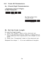
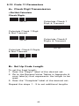
C> Check Digit Transmission
UPC-A Check Digit
Transmission <ON>
OFF
%0 AI 2
UPC-E Check Digit
Transmission <ON>
%0 AI 0
OFF
%0 BI 2
EAN-8 Check Digit
Transmission <ON>
%0 BI 0
OFF
%0 A8 8
EAN-13 Check Digit
Transmission <ON>
%0 A8 0
OFF
%0 AH1
ISSN Check Digit
Transmission <ON>
%0 AH0
OFF
%0 BK4
%0 BK0
25
5.3 Code 39 Parameters
A> Type of Code
<Standard>
Full ASCII
%0 EH1
%0 EH0
Italian Pharmacy/Code 32
<OFF>
Italian Pharmacy/
Code 32 ON
%0 E8 0
%0 E8 8
B> Check Digit Transmission
<Do Not Calculate
Check Digit>
Calculate Check Digit
& Transmit
%0 EM2
Calculate Check Digit
& Not Transmit
%0 EM6
%0 EM4
C> Output Start/Stop Character
Enable
<Disable>
%0 E4 4
%0 E4 0
26
D> Decode Asterisk
Enable
<Disable>
%0 E2 2
%0 E2 0
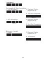
E> Set Up Code Length
To set the fixed length:
1. Scan the "Begin" label of the desired set.
2. Go to the Decimal Value Tables in Appendix A,
scan label(s) that represents the length to be
read.
3. Scan the "Complete" label of the desired set.
Repeat the steps 1 - 3 to set additional lengths.
<Variable>
%4 E1 +
Fix Length (2 Sets Available)
1. 1st Set Begin
2. Decimal Value
(Appendix A)
3. 1st Set Complete
%4 E0 0
%4 E0 1
1. 2nd Set Begin
2. Decimal Value
(Appendix A)
3. 2nd Set Complete
%4 E0 0
%4 E0 2
Minimum Length
1. Begin
2. Decimal Value
(Appendix A)
3. Complete
%2 + - /
%2 C0 +
27
5.4 Code 128 Parameters
A> Reading Type
UCC/EAN-128
Enable
<UCC/EAN-128
Disable>
%0 F4 4
<Enable']C1'Code
Format>
%0 F4 0
Disable']C1'Code
Format
%0 F2 2
<Enable Code128 Group
Separators (GS)>
%0 F2 0
Disable Code128
Group Separators
(GS)
%0 F1 1
%0 F1 0
B> Check Digit Transmission
Do Not Calculate
Check Digit
%0 FN1
Calculate Check
Digit & Transmit
<Calculate Check Digit
& Not Transmit>
%0 FN7
%0 FN5
C> Append FNC2
ON
<OFF>
%0 F8 8
%0 F8 0
28
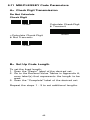
D> Set Up Code Length
To set the fixed length:
1. Scan the "Begin" label of the desired set.
2. Go to the Decimal Value Tables in Appendix A,
scan label(s) that represents the length to be
read.
3. Scan the "Complete" label of the desired set.
Repeat the steps 1 - 3 to set additional lengths.
<Variable>
%4 F1 +
Fix Length (2 Sets Available)
1. 1st Set Begin
2. Decimal Value
(Appendix A)
%4 F0 0
3. 1st Set Complete
%4 F0 1
1. 2nd Set Begin
2. Decimal Value
(Appendix A)
%4 F0 0
3. 2nd Set Complete
%4 F0 2
Minimum Length
1. Begin
2. Decimal Value
(Appendix A)
%2 + - /
3. Complete
%2 C1 +
29
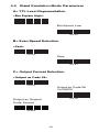
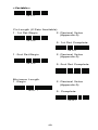
5.5 Interleave 25 Parameters
A> Check Digit Transmission
<Do Not Calculate
Check Digit>
Calculate Check Digit
& Transmit
%0 GN3
Calculate Check Digit
& Not Transmit
%0 GN7
%0 GN5
B> Set Up Number of Character
<Even>
Odd
%0 G8 8
%0 G8 0
C> Brazilian Banking Code
<Disable>
Enable
%0 G4 0
%0 G4 4
30
D> Set Up Code Length
To set the fixed length:
1. Scan the "Begin" label of the desired set.
2. Go to the Decimal Value Tables in Appendix A,
scan label(s) that represents the length to be
read.
3. Scan the "Complete" label of the desired set.
Repeat the steps 1 - 3 to set additional lengths.
<Variable>
%4 G1 +
Fix Length (2 Sets Available)
1. 1st Set Begin
2. Decimal Value
(Appendix A)
3. 1st Set Complete
%4 G0 0
%4 G0 1
1. 2nd Set Begin
2. Decimal Value
(Appendix A)
3. 2nd Set Complete
%4 G0 0
%4 G0 2
Minimum Length
1. Begin
2. Decimal Value
(Appendix A)
3. Complete
%2 + - /
%2 C2 +
31
5.6 Industrial 25 Parameters
A> Reading type
IATA25 Enable
<Disable>
%0 H4 4
%0 H4 0
B> Check Digit Transmission
<Do Not Calculate
Check Digit>
Calculate Check Digit
& Transmit
%0 HN3
%0 HN7
Calculate Check Digit
& Not Transmit
%0 HN5
C> Set Up Code Length
To set the fixed length:
1. Scan the "Begin" label of the desired set.
2. Go to the Decimal Value Tables in Appendix A,
scan label(s) that represents the length to be
read.
3. Scan the "Complete" label of the desired set.
Repeat the steps 1 - 3 to set additional lengths.
32
<Variable>
%4 H1 +
Fix Length (2 Sets Available)
1. 1st Set Begin
2. Decimal Value
(Appendix A)
%4 H0 0
3. 1st Set Complete
%4 H0 1
1. 2nd Set Begin
2. Decimal Value
(Appendix A)
%4 H0 0
3. 2nd Set Complete
%4 H0 2
Minimum Length
1. Begin
2. Decimal Value
(Appendix A)
%2 + - /
3. Complete
%2 C3 +
33
5.7 Matrix 25 Parameters
A> Check Digit Transmission
<Do Not Calculate
Check Digit>
%0 I N3
Calculate Check Digit
& Transmit
%0 I N7
Calculate Check Digit
& Not Transmit
%0 I N5
B> Set Up Code Length
To set the fixed length:
1. Scan the "Begin" label of the desired set.
2. Go to the Decimal Value Tables in Appendix A,
scan label(s) that represents the length to be
read.
3. Scan the "Complete" label of the desired set.
Repeat the steps 1 - 3 to set additional lengths.
34
<Variable>
%4 I 1 +
Fix Length (2 Sets Available)
1. 1st Set Begin
2. Decimal Value
(Appendix A)
%4 I 0 0
3. 1st Set Complete
%4 I 0 1
1. 2nd Set Begin
2. Decimal Value
(Appendix A)
%4 I 0 0
3. 2nd Set Complete
%4 I 0 2
Minimum Length
1. Begin
2. Decimal Value
(Appendix A)
%2 + - /
3. Complete
%2 C4 +
35
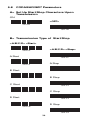
5.8 CODABAR/NW7 Parameters
A> Set Up Start/Stop Characters Upon
Transmission
ON
<OFF>
%0 J H1
%0 J H0
B> Transmission Type of Start/Stop
<A/B/C/D> <Start>
<A/B/C/D> <Stop>
%0 4 VF
A Start
%0 4 FF
A Stop
%0 4 V1
B Start
%0 4 F1
B Stop
%0 4 V2
C Start
%0 4 F2
C Stop
%0 4 V4
D Start
%0 4 F4
D Stop
%0 4 V8
%0 4 F8
36
C> Set Up Code Length
To set the fixed length:
1. Scan the "Begin" label of the desired set.
2. Go to the Decimal Value Tables in Appendix A,
scan label(s) that represents the length to be
read.
3. Scan the "Complete" label of the desired set.
Repeat the steps 1 - 3 to set additional lengths.
<Variable>
%4 J 1 +
Fix Length (2 Sets Available)
1. 1st Set Begin
2. Decimal Value
(Appendix A)
%4 J 0 0
3. 1st Set Complete
%4 J 0 1
1. 2nd Set Begin
2. Decimal Value
(Appendix A)
%4 J 0 0
3. 2nd Set Complete
%4 J 0 2
Minimum Length
1. Begin
2. Decimal Value
(Appendix A)
%2 + - /
3. Complete
%2 C5 +
37
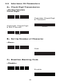
5.9 Code 93 Parameters
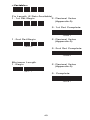
A> Check Digit Transmission
<Calculate Check 2 Digits
& Not Transmit>
%0 KN4
Do Not Calculate
Check Digit
%0 KN3
B> Set Up Code Length
To set the fixed length:
1. Scan the "Begin" label of the desired set.
2. Go to the Decimal Value Tables in Appendix A,
scan label(s) that represents the length to be
read.
3. Scan the "Complete" label of the desired set.
Repeat the steps 1 - 3 to set additional lengths.
38
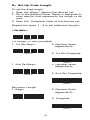
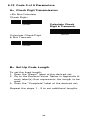
<Variable>
%4 K1 +
Fix Length (2 Sets Available)
1. 1st Set Begin
2. Decimal Value
(Appendix A)
%4 K0 0
3. 1st Set Complete
%4 K0 1
1. 2nd Set Begin
2. Decimal Value
(Appendix A)
%4 K0 0
3. 2nd Set Complete
%4 K0 2
Minimum Length
1. Begin
2. Decimal Value
(Appendix A)
%2 + - /
3. Complete
%2 C6 +
39
5.10 Code 11 Parameters
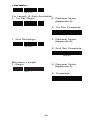
A> Check Digit Transmission
<Do Not Calculate
Check Digit>
Calculate Check 1
Digit & Transmit
%0 L N3
%0 L N7
Calculate Check 1 Digit
& Not Transmit
Calculate Check 2
Digits & Transmit
%0 L N5
%0 L N6
Calculate Check 2 Digits
& Not Transmit
%0 L N4
B> Set Up Code Length
To set the fixed length:
1. Scan the "Begin" label of the desired set.
2. Go to the Decimal Value Tables in Appendix A,
scan label(s) that represents the length to be
read.
3. Scan the "Complete" label of the desired set.
Repeat the steps 1 - 3 to set additional lengths.
40
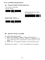
<Variable>
%4 L 1 +
Fix Length (2 Sets Available)
1. 1st Set Begin
2. Decimal Value
(Appendix A)
%4 L 0 0
3. 1st Set Complete
%4 L 0 1
1. 2nd Set Begin
2. Decimal Value
(Appendix A)
%4 L 0 0
3. 2nd Set Complete
%4 L 0 2
Minimum Length
1. Begin
2. Decimal Value
(Appendix A)
%2 + - /
3. Complete
%2 C7 +
41
5.11 MSI/PLESSEY Code Parameters
A> Check Digit Transmission
Do Not Calculate
Check Digit
Calculate Check Digit
& Transmit
%0 NN3
%0 NN7
<Calculate Check Digit
& Not Transmit>
%0 NN5
B> Set Up Code Length
To set the fixed length:
1. Scan the "Begin" label of the desired set.
2. Go to the Decimal Value Tables in Appendix A,
scan label(s) that represents the length to be
read.
3. Scan the "Complete" label of the desired set.
Repeat the steps 1 - 3 to set additional lengths.
42
<Variable>
%4 N1 +
Fix Length (2 Sets Available)
1. 1st Set Begin
2. Decimal Value
(Appendix A)
%4 N0 0
3. 1st Set Complete
%4 N0 1
1. 2nd Set Begin
2. Decimal Value
(Appendix A)
%4 N0 0
3. 2nd Set Complete
%4 N0 2
Minimum Length
1. Begin
2. Decimal Value
(Appendix A)
%2 + - /
3. Complete
%2 C9 +
43
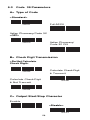
5.12 Code 2 of 6 Parameters
A> Check Digit Transmission
<Do Not Calculate
Check Digit>
Calculate Check
Digit & Transmit>
%0 PN3
%0 PN7
Calculate Check Digit
& Not Transmit
%0 PN5
B> Set Up Code Length
To set the fixed length:
1. Scan the "Begin" label of the desired set.
2. Go to the Decimal Value Tables in Appendix A,
scan label(s) that represents the length to be
read.
3. Scan the "Complete" label of the desired set.
Repeat the steps 1 - 3 to set additional lengths.
44
<Variable>
%4 P1 +
Fix Length (2 Sets Available)
1. 1st Set Begin
2. Decimal Value
(Appendix A)
%4 P0 0
3. 1st Set Complete
%4 P0 1
1. 2nd Set Begin
2. Decimal Value
(Appendix A)
%4 P0 0
3. 2nd Set Complete
%4 P0 2
Minimum Length
1. Begin
2. Decimal Value
(Appendix A)
%2 + - /
3. Complete
%2 CB+
45
5.13 LCD25 Parameters
A> Check Digit Transmission
<Do Not Calculate
Check Digit>
Calculate Check Digit
& Transmit
%0 QN3
%0 QN7
Calculate Check
Digit & Not Transmit
%0 QN5
B> Setup Code Length
To set the fixed length:
1. Scan the "Begin" label of the desired set.
2. Go to the Decimal Value Tables in Appendix A,
scan label(s) that represents the length to be
read.
3. Scan the "Complete" label of the desired set.
Repeat the steps 1 - 3 to set additional lengths.
46
<Variable>
%4 Q1 +
Fix Length (2 Sets Available)
1. 1st Set Begin
2. Decimal Value
(Appendix A)
%4 Q0 0
3. 1st Set Complete
%4 Q0 1
1. 2st Set Begin
2. Decimal Value
(Appendix A)
%4 Q0 0
3. 2nd Set Complete
%4 Q0 2
Minimum Length
1. Begin
2. Decimal Value
(Appendix A)
%2 +- /
3. Complete
%2 CC+
47
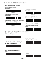
5.14 Telepen Parameters
A> Type of Code
<Full ASCll Mode>
Compressed Numeric
Mode
%0 T8 0
%0 T8 8
B> Check Digit Transmission
Do Not Calculate
Check Digit
%0 TN3
Calculate Check
Digit & Transmit
<Calculate Check Digit
& Not Transmit>
%0 TN7
%0 TN5
C> Set Up Code Length
To set the fixed length:
1. Scan the "Begin" label of the desired set.
2. Go to the Decimal Value Tables in Appendix A,
scan label(s) that represents the length to be
read.
3. Scan the "Complete" label of the desired set.
Repeat the steps 1 - 3 to set additional lengths.
48
<Variable>
%4 T1 +
Fix Length (2 Sets Available)
1. 1st Set Begin
2. Decimal Value
(Appendix A)
%4 T0 0
3. 1st Set Complete
%4 T0 1
1. 2nd Set Begin
2. Decimal Value
(Appendix A)
%4 T0 0
3. 2nd Set Complete
%4 T0 2
Minimum Length
1. Begin
2. Decimal Value
(Appendix A)
%2 %+- /
3. Complete
%2 CF+
49
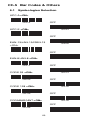
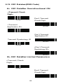
5.15 GS1 Databar(RSS Code)
A> GS1 DataBar Omnidirectional ON
<Transmit Check
Digit>
Don't Transmit
Check Digit
%0 UN7
<Transmit
Application ID>
%0 UN5
%0 U8 8
Don't Transmit
Application ID
Transmit Symbology ID
%0 U8 0
%0 U4 4
<Don't Transmit
Symbology ID>
%0 U4 0
B> GS1 DataBar Limited Parameters
<Transmit Check
Digit>
%0 VN7
Don't Transmit
Check Digit
%0 VN5
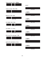
50
<Transmit Application ID>
%0 V8 8
Don't Transmit
Application ID
Transmit Symbology ID
%0 V8 0
%0 V4 4
<Don't Transmit
Symbology ID>
%0 V4 0
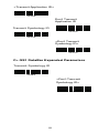
C> GS1 DataBar Expanded Parameters
Transmit Symbology ID
%0 W4 4
<Don't Transmit
Symbology ID>
%0 W4 0
51
Ch.6 Miscellaneous Parameters
6.1 Language Selection
<US English>
%0 ZV0
UK English
%0 ZV1
Italian
%0 ZV2
Spanish
%0 ZV3
French
%0 ZV4
German
%0 ZV5
Swedish
%0 ZV6
Switzerland
%0 ZV7
Hungarian
%0 ZV8
Japanese
%0 ZV9
52
Belgium
%0 ZVA
Portuguese
%0 ZVB
Denmark
%0 ZVC
Netherlands
%0 ZVD
Turkey
%0 ZVE
Reserved2
%0 ZVF
53
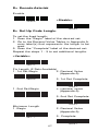
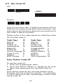
6.2 Bar Code ID
ON
<OFF>
%0 0 H1
%0 0 H0
Default
%9 1 3 +
With this function ON, a leading character will be
added to the output string while scanning code, user
may refer to the following table to know what kind of
bar code is being scanned.
Please refer to the table below for matching code
ID of codes read in.
Code Type
ID
UPC-A
A
EAN-8
C
CODE 39
E
Interleave 25
G
Matrix 25
I
CODE 93
K
China Postage M
Code 2 of 6
P
Telepen
T
RSS Limited
V
Code Type
UPC-E
EAN-13
CODE 128
Industrial 25
Codabar/NW7
CODE 11
MSI/PLESSEY
LCD25
RSS-14
RSS Expanded
ID
B
D
F
H
J
L
N
Q
U
W
User Define Code ID
To set the code ID:
1. Scan the symbologies label.
2. Go to the ASCII Tables in Appendix B, scan
label that represents the desired code ID.
Note:
User define code ID will override default value.
Program will not check the conflict. It is possible
to have more than two symbologies which have
same code ID.
54
UPC-A
UPC-E
%9 1 A+
EAN-13/JAN-13
%9 1 B+
EAN-8/JAN-8
%9 1 Y+
CODE 39
%9 1 Z+
CODE 128
%9 1 E+
CODABAR/NW7
%9 1 F+
Interleave 25
%9 1 J +
Industrial 25
%9 1 G+
Matrix 25
%9 1 H+
CODE 93
%9 1 I +
CODE 11
%9 1 K+
China Postage
%9 1 L +
MSI/PLESSEY
%9 1 M+
%9 1 N+
55
Code 2 of 6
%9 1 P+
Telepen
%9 1 T+
LCD25
%9 1 Q+
RSS-14
%9 1 U+
RSS Limited
%9 1 V+
RSS Expanded
%9 1 W+
Reserved5
%9 1 R+
Reserved6
%9 1 S+
56
6.3 Reading Level
Bar Equals High
<Bar Equals Low>
%0 3 I 2
6.4 Accuracy
%0 3 I 0
<1 Time>
2 Times
%0 1 3 0
3 Times
%0 1 3 1
4 Times
%0 1 3 2
6.5 Buzzer Beep Tone
%0 1 3 3
<High>
Medium
%0 1 J 3
Low
%0 1 J 2
Off
%0 1 J 1
%0 1 J 0
6.6 LED Control(SV700 only)
<ON>
OFF
%0 9 O8
%0 9 O0
57
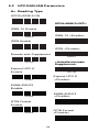
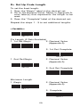
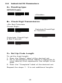
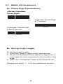
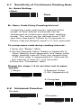
6.7 Sensitivity of Continuous Reading Mode
A> Quick Setting:
<Fast>
Slow
%0 3 8 8
%0 3 8 0
B> Same Code Delay Reading Interval
Following code sequences represent the
length of time before a barcode can be
rescanned at continuous and flash reading
mode. The value can be defined from 1-50
and they represent 100ms to 5 seconds in
100ms interval.Default value is 3 (0.3 seconds).
To setup same code delay reading interval:
1.Scan the "Begin" label
2.Go the Decimal Value Tables in Appendix A,
Scan label(s),that represents the same code
delay reading interval.They are ranged form
1-50.One step is represented 0.1second.So
the interval is from 0.1 to 5 seconds.
3.Scan the "Complete" label
Repeat the steps 1-3 to set time out of same
symbol
1.Begin
2.Decimal Value
(1-50) (Appendix A)
%3 0 0 0 0
3.Complete
%3 0 0 0 1
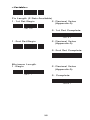
6.8 Notebook Function
Enable
<Disable>
%0 3 4 4
%0 3 4 0
58
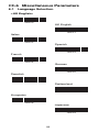
6.9 Reverse Output Characters
<Disable>
%0 3 H0
Enable
6.10 Setup Deletion
%0 3 H1
To setup the deletion of output characters:
1. Scan the label of the desired set below.
2. Scan the label of the desired symbology.
3. Go to the Decimal Value Tables in Appendix A,
scan label(s) that represents the desired
position to be deleted.
4. Scan the "Complete" label of "Character Position
to be Deleted".
5. Go to the Decimal Value Tables in Appendix A,
scan label(s) that represents the number of
characters to be deleted.
6. Scan the "Complete" label of "Number of
Characters to be Deleted".
Repeat the steps 1 - 6 to set additional deletion.
A> Select Deletion Set Number
1. 1st Set
2. 2nd Set
%8 0 0 +
3. 3rd Set
%8 0 1 +
4. 4th Set
%8 0 2 +
5. 5th Set
%8 0 3 +
6. 6th Set
%8 0 4 +
%8 0 5 +
59
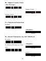
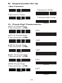
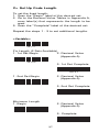
B> Symbologies Selection
UPC-A
UPC-E
%8 1 A+
EAN-13/JAN-13/ISBN-13
%8 1 B+
EAN-8/JAN-8
%8 1 Y+
CODE 39
%8 1 Z+
CODE 128
%8 1 E+
CODABAR/NW7
%8 1 F+
Interleave 25
%8 1 J +
Industrial 25
%8 1 G+
Matrix 25
%8 1 H+
CODE 93
%8 1 I +
CODE 11
%8 1 K+
China Postage
%8 1 L +
MSI/PLESSEY
%8 1 M+
%8 1 N+
60
Code 2 of 6
Telepen
%8 1 P+
LCD25
%8 1 T+
RSS-14
%8 1 Q+
RSS Limited
%8 1 U+
RSS Expanded
%8 1 V+
All Codes
%8 1 W+
None
%8 1 S+
%8 1 4 +
C> Character Position to be Deleted
1. Decimal Value
(Appendix A)
2. Complete
%8 2 0 +
D> Number of Characters to be Deleted
1. Decimal Value
(Appendix A)
2. Complete
%8 3 0 +
61
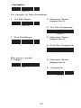
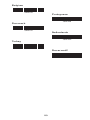
6.11 Setup Insertion
To setup the insertion of output characters:
1. Scan the label of the desired set.
2. Scan the label of the desired symbology.
3. Go to the Decimal Value Tables in Appendix A, scan
label(s) that represents the desired position to be
inserted.
4. Scan the "Complete" label of "Character Position
to be Inserted".
5. Go to the ASCII Tables in Appendix B or Function
Key Tables in Appendix C, scan label(s) that
represents the desired characters to be inserted.
6. Scan the "Complete" label of "Characters to be
Inserted".
Repeat the steps 1 - 6 to set additional insertion.
A> Select Insertion Set Number
1. 1st Set
2. 2nd Set
%5 0 0 +
3. 3rd Set
%5 0 1 +
4. 4th Set
%5 0 2 +
5. 5th Set
%5 0 3 +
6. 6th Set
%5 0 4 +
%5 0 5 +
62
B> Symbologies Selection
UPC-A
UPC-E
%5 1 A+
EAN-13/JAN-13/ISBN-13
%5 1 B+
EAN-8/JAN-8
%5 1 Y+
CODE 39
%5 1 Z+
CODE 128
%5 1 E+
CODABAR/NW7
%5 1 F+
Interleave 25
%5 1 J +
Industrial 25
%5 1 G+
Matrix 25
%5 1 H+
CODE 93
%5 1 I +
CODE 11
%5 1 K+
China Postage
%5 1 L +
MSI/PLESSEY
%5 1 M+
%5 1 N+
63
Code 2 of 6
Telepen
%5 1 P+
%5 1 T+
LCD25
RSS-14
%5 1 Q+
%5 1 U+
RSS Limited
RSS Expanded
%5 1 V+
%5 1 W+
All Codes
None
%5 1 S+
%5 1 4 +
C> Character Position to be Inserted
1. Decimal Value
(Appendix A)
2. Complete
%5 2 0 +
D> Characters to be Inserted
1. ASCII Table
(Appendix B)
2. Complete
%5 3 0 +
64
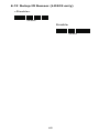
6.12 Setup IR Sensor (LG303 only)
<Disable>
%0 XH0
Enable
%0 XH1
65
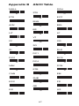
Appendix A Decimal Value Table
0
1
2
3
4
5
6
7
8
9
66
Appendix B ASCII Table
NULL
00
SOH
STX
ETX
01
02
03
ENQ
ACK
04
05
06
07
08
0A
0B
0D
0E
10
11
13
14
16
17
19
1A
RS
EM
SUB
ESC
1B
SYN
ETB
CAN
18
DC3
DC4
NAK
15
DLE
DC1
DC2
12
CR
SO
SI
0F
LF
VT
FF
0C
BEL
BS
HT
09
EOT
FS
GS
1C
1D
1E
US
1F
67
SPACE
20
!
"
#
21
22
23
%
&
24
25
26
27
28
2A
2B
2D
2E
30
31
33
34
36
37
39
3A
>
9
:
;
3B
6
7
8
38
3
4
5
35
0
1
2
32
-
.
/
2F
*
+
,
2C
'
(
)
29
$
<
=
3C
3D
3E
?
3F
68
@
A
40
B
C
41
42
43
E
F
44
45
46
47
48
4A
4B
4D
4E
50
51
53
54
56
57
59
5A
^
Y
Z
[
5B
V
W
X
58
S
T
U
55
P
Q
R
52
M
N
O
4F
J
K
L
4C
G
H
I
49
D
\
]
5C
5D
5E
_
5F
69
`
a
60
b
c
61
62
63
e
f
64
65
66
67
68
6A
6B
6D
6E
70
71
73
74
76
77
79
7A
~
y
z
{
7B
v
w
x
78
s
t
u
75
p
q
r
72
m
n
o
6F
j
k
l
6C
g
h
i
69
d
|
}
7C
7D
7E
DEL
7F
70
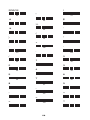
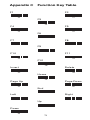
Appendix C Function Key Table
F1
F2
C0
C1
F3
C2
F4
F5
C3
C4
F6
C5
F7
F8
C6
C7
F9
C8
F10
F11
C9
CA
F12
CB
Insert
Delete
CC
CD
Home
CE
Page Up
Page Down
CF
D0
End
D1
Left
Right
D2
D3
Up
D4
Down
D5
71
Save Parameters
%$ + / 0
Recall Stored
Parameters
%$ + / 1
Set All Defaults
%$ + / 2
Start Configuration
%$ + / 3
End Configuration
%$ + / 4
Abort Configuration
%$ + / 6
Version Information
%$ + / 5
Ver 3.8 a
0145-85E00J1