1
1 Thermaltake
Coocrall YOUR LIFE
Amos MX
Beyond the past, Exceed the present,
Surpass the competition
N
HOW
PL
E
*
Thermaltake
Coocall YOUR LIFE
©2008 Thermaltake Technology Co., Ltd. All Rights Reserved. 2008.02
All other registered trademarks belong to their respective companies. www.thermaltake.com
Tested To Comply CE
With FCC Standards
|__|
FOR HOME OR OFFICE USE
Chapter |. Product Introduction
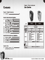
Contents Specification
Chapter 1. Product Introduction
1.1 Specification ------------<<<--""<<<000cceeeee ec eee een cc een nc seen 02
Chapter 2. Case Mechanical Operation
2.1 How to Open the Side Panel -----77-77--77770000000teteen 03
-Ореп the left-hand side panel -------------======"=====-—" 03
-Open the right-hand side panel ---------==-==========="==- 04
2.2 50215 | IDevidel [NSstalla Ion) Er Eh SETH {ria wl ek qe TE TE 05
I | Model VH8000BWS VH8000SWA
NOW tol fine moe (5825 Hid eV (icedl an rina ii mini 06
-How to put back the 5.25" drive bay cover ---------- 06 Case Type Middle Tower
2.3 BEN Device Mnstallatro na | | E Tre E al wale Gis 07 Dimension (H*W*D) i 1 O 514 ME
2 4 H D D In sta | latio TE A a a el TOI 08 Side panel Transparent window Transparent window
2.5 How to Remove the HDD Cage ihe rtd md tn Se TE A dt Ti 10 Cable management Yes Yes
2.6 Fl Slot iool-Fite Misa gle 155: i 55 Er ide hina As 11 lod lider Yes Yes
2.7 Power Supply Installatie nd IHS Lib a Coan LLL ER 12 mecs Front door: em choses 0.8mm SECC Front door: Amine Chassis: 0.8mm AL
olor ac liver
2.8 Aceesso y | Storade nes y: do sal of lb ie 13
Front (intake) : Front (intake) :
120 x 120 x 25 mm blue LED fan, 120 x 120 x 25 mm blue LED fan,
° 1300rpm, 17dBA 1300rpm, 17dBA
Chapter3 Motherboard & Leads Installation SEUL COLIS | ООО
(AED {| (0 CLS AT AO (I) HUMES og Cooling System 120 x 120 x 25 mm TurboFan, 120 x 120 x 25 mm TurboFan,
3.1 Motherboard Installation 14 SEELEN] KIEL fe dra Arig
3.2 Case LED Icon necton E A he ANA ii 15 Side (intake) : Side (intake) :
J 230 x 230 x 20 mm blue LED fan, 230 x 230 x 20 mm blue LED fan,
3.3 ni 2.0 ni FN 16 800rpm, 15dBA 800rpm, 15dBA
3.4 Audio Connection if ide nn deen ner wien iran 17
3 5 e SAMA connecti ra A ALA. UL 1 BLL LAL 17 Motherboards 9.6" x 9.6" (Micro ATX), 12" x 9.6" (ATX)
| Drive Bays
-5.25" Drive Bay 5
-3.5" Drive Bay 1
-3.5" Drive Bay (Hidden) 4
Chapter4 Other
Front 1/0 e-SATA connector x 1, USB 2.0 x 2, HD Audio
4.1 Toughpower / Purepower / TR2 --------=========ccee=eneeea 18 Expansion Slots 7
power supply series (optional)
Amon MX VH8000 Series Beyond the past, Exceed the present, Surpass the competition
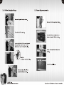
Chapter 2 Case Mechanical Operation
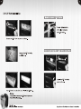
2.1 How to Open the Side Panel
Open the left-hand side panel Open the right-hand side panel
To remove the left-hand side panel,
please remove thumb screws on the
back of the case. To remove the right-hand side panel,
please remove screws on the back of
the case.
Push the buttons, then pull out
the side panel.
Pull out the right-hand side panel as
arrow shows.
VH8000 Series Beyond the past, Exceed the present, Surpass the competition
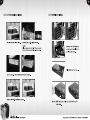
2.2 5.25" Device Installation
remove 5.25" device
Pull the right-hand side
of the lever to remove
the 5.25" device.
How to put back the 5.25" drive bay cover
Remove the 5.25" drive bay
metal cover.
Install the 5.25" drive bay
cover as shown.
Put 5.25" device into the drive bay till the locked-position.
Notice:
It is possible to secure the 5.25" device by screws
if not feel stable enough.
Amon MX VH8000 Series Beyond the past, Exceed the present, Surpass the competition
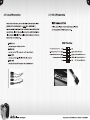
2.3 3.5" Device Installation 2.4 HDD Installation
Unlock the tool-free clip. Remove the 3.5" plastic cover.
Notice:
Please remove the 1st 5.25" drive bay cover
before taking away the 3.5" plastic cover.
Remove the HDD tray by
pressing the handle and
pull the tray out.
Place HDD on the tray.
: Le
ET )
7 —
7% °
Secure HDD using the clips onto the HDD tray for
both side.
Amon MX VH8000 Series Beyond the past, Exceed the present, Surpass the competition
Slide the HDD tray back to
the drive bay.
Organized HDD cable
management.
Hell ef) UN Q
1
Ар VEX VH8000 Series
2.5 How to Remove the HDD Cage
Unscrew the thumb screws of
the cage.
Push the handle down and pull
the cage out.
Beyond the past, Exceed the present, Surpass the competition
2.6
PCI Slot Tool-Free Usage
Release the plastic clip as shown.
Take off the PCI bracket.
Locate Graphic Card to the motherboard
through fixing it on the space of PCI
bracket and insert it to the PCI slot.
Notice:
Fix the pin into the hole.
Push back the plastic clip to
secure the Graphic Card.
Ар VEX VH8000 Series
Power Supply Installation
Unscrew the PSU supporting bridge.
Place the PSU over the location as
shown and secure PSU by screws.
Fasten the supporting bridge using
screws.
Finish PSU installation.
Beyond the past, Exceed the present, Surpass the competition
Chapter3 Motherboard & Leads Installation
2.8 Accessory Storage 3.1 Motherboard Installation
Each motherboard has different standoff layout. Itis highly
suggested that you refer to your motherboard's manual when
installing motherboard into the Case. Armor+ MX is applicable
with , ATX & Micro ATX motherboards. Your motherboard may
require a special I/O Panel, which should be included with your
motherboard.
Placement Direction:
When installing the motherboard, make sure you follow the
direction provided by your motherboard manufacturer. On
storage space for small tools and accessories. most standard motherboards, the edge with external ports
goes to the rear part of the chassis. Itis highly recommended
that you install CPU, heat sink and modular components
before fixing the motherboard inside the chassis.
The top sliding hood allows easy access to the extra
O = the locations of
the screw holes. Note
these locations and
place included
standoffs on the chassis
first.
Press to remove the accessory storage if necessary. This side towards
the rear of the
chassis
<
Above illustration is a sample of what
the motherboard's layout. For more
detail screw hole placement, please
refer to your motherboard manual.
Amon MX VH8000 Series Beyond the past, Exceed the present, Surpass the competition
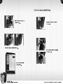
3.2 Case LED connection
On the front of the case, you can find some LEDs and switch leads
(POWER SW*1, POWER LED*1, H.D.D. LED*1, RESET SW*1)
Please consult user manual of your motherboard manufacturer, then
connect these leads to the panel header on the motherboard. These
leads are usually labeled; if not, please trace them back to the case
front to find out their source.
POWER LED
connects to your M/B at the PLED
POWER SW
connects to the PWR connector on the motherboard
H.D.D LED
connects to the 2-pin labeled HDD LED connector
RESET SW
connects to the RSW connector on the motherboard
Eo — 7”
H.D.D; LED
Ар VEX VH8000 Series
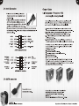
3.3 USB 2.0 Connection
USB connection
Please consult your motherboard manual to find
out the section of "USB connection”.
USB Function
VCC / USB Power (+5C) for Port 4 NC
-D / USB Negative Signal for Port 4 WHITE BLACK GROUND / USB Ground
+D / USB Positive Signal for Port 4 GREEN GREEN +D / USB Positive Signal for Port 3
GROUND / USB Ground BLACK WHITE -D/ USB Negative Signal for Port 3
KEY RED VCC / USB Power (+5C) for Port 3
Beyond the past, Exceed the present, Surpass the competition
3.4 Audio Connection
® Please refer to the following illustration
of Audio connector and your motherboard
user manual.
® Please select the motherboard which used
AC'97 or HD Audio (Azalia), (be aware of
that your audio supports AC'97 or HD Audio
(Azalia)) or it will damage your device(s).
* On some motherboards, the connectors for Audio are not the same
as the drawing below. Please check with your motherboard manual
before installing.
PORTI L RED BLACK AUD GND
PORTIR BROWN
PORT2R YELLOW
SENSE SEND PURPLE KEY
PORT2 L BLUE
AUDIO AZALIA Function
Front Microphone
input Signal MIC IN BLACK GROUND
Front Microphone MIC POWER BROWN NC
Front Right Channel
Audio Signal R-OUT YELLOW YELLOW R-RET
NC KEY
Front Left Channel
Audio Signal L-OUT BLUE BLUE L-RET
AUDIO AC'97 Function
3.5 eSATA connection
Ар VEX VH8000 Series
BLACK PRESENCE#
Connect this to your
motherboard at SATA.
ORANGE SENSEI RETURN
GREEN SENSE2 RETURN
Front
Audio Ground
Rear Right Channel
Audio Signal
Rear Left Channel
Audio Signal
Chapter4 Other
4.1 Toughpower / Purepower / TR2
power supply series (optional)
The Thermaltake Power Supply series specification meets latest Intel &
AMD dual & Quad core processors and NVIDIA & AMD high performance
graphic cards; it offers plenty of functions, which mainly include:
1. Automatic Fan Speed Control: All power supply can detect the inside
heat and automatically adjust the fan speed to provide adequate airflow.
2. Ultra Silent: Ball bearing fans with high reliability 140mm or 120mm
cooling fan and super low acoustic noise under all load condition.
3. Modularized Cable Management: To eliminate clutter and improve
airflow inside the case.
4. Dedicated Graphic Card Power: reduce the loading on current PSU and
no need to upgrade current PSU while running multi graphic cards mode.
The functions can assure all Thermaltake Power Supply meets the balance
in noise control and heat exhausted. All power supply provides complete
protection function as follow:
1. Over power protection.
2. Short circuit protection on all output.
3. Over voltage protection / Under voltage protection.
4. Over current protection.
5. Over temperature protection.
Besides, Thermaltake enables the quality assurance of all power supply:
100% Hi-POT and ATE Function Test, 100% Burn-In and AC Input cycled
on/off under high temperature condition. Furthermore, it has been approved
by UL, CUL, TUV, CB, FCC, CE, and BSMI.
There are three main products line of Thermaltake PSU
which divided into Toughpower, Purepower (include
Purepower RX) and TR2 (include TR2 RX) series.
Please refer to
http://www.thermaltake.com/product/Power/power_index.asp
Beyond the past, Exceed the present, Surpass the competition