1
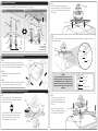
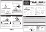
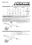
F
Attaching the Flush Mount Assembly to the Ceiling Plate
F.1.
Connect the Shaft to the Ceiling Plate as shown
below.
M8 Nyloc Nut
Shaft
Locking
Hook
TELEHOOK
Please read these
instructions before
commencing installation
as faulty installation could
result in injury. Atdec
assumes no responsibility
for faulty installations.
F.3.
Tighten the Locking Hook with the M8x50mm
Socket Cap Screw and the M8 Nyloc Nut that
was previously removed.
Ceiling Plate
Installation Instructions
IMPORTANT
M8x50mm
Socket Cap
Screw
universal projector flush mount
WARNING: This bracket supports up to 15kg (33lbs).
DO NOT overload this bracket.
Component Checklist
Bits Bag
Flush Mount
Assembly (x1)
6mm
Allen Key
F.2.
Insert the
Locking Hook
into the slot in
the Ceiling Plate
to lock the Flush
Mount Assembly.
Flush Mount
and Projector
Extension Brackets
150mm (x2)
Locking
Hook
Extension
Brackets
50mm (x2)
Extension
Brackets
100mm (x2)
Extension Brackets
75mm (x2)
Tip: When the projector requires servicing, remove
the projector via this easy disconnection point to
save time.
Square Nut (x8)
M5x10mm
Socket Button
Cap Screw (x4)
6mm Allen
Key (x1)
Bottom
Cross Recessed Screws
Spacer (x4)
M2.5x15 (x4)
M3x15 / M3x20 (x4 each)
M4x15 / M4x20 / M4x25 (x4 each)
M5x15 / M5x20 / M5x25 (x4 each)
M6x15 / M6x20 / M6x25 (x4 each)
Nylon Anchor
Plug (x2)
3mm Allen
Key (x1)
Washer
20mm (x2)
10mm (x4)
8mm (x4)
14 Gauge Coach Screw (x2)
Spacer
Large (x4)
Medium (x4)
Small (x4)
WARNING
G
Ensure the Ceiling can support the total weight of the Projector and the Universal Flush Mount.
Adjusting the Projector
Roll / Shift Adjustment
M8x65mm
Screw
All bolts and screws must be used at the designated points in the installation instructions to prevent damage
to the projector, or personal injury.
Pitch Adjustment
Loosen
6mm
Allen Key
6mm
Allen Key
Loosen
DO NOT install near air conditioner vents or where there is excessive dust or smoke.
M8x15mm
Screw
Ensure the projector is mounted so that it is not possible for excessive loads to be placed on the bracket.
6mm
Allen Key
Tighten
a
Tighten
Roll
Roll
Pitch
Check you have received all parts against the Component Checklist above.
Pitch
b
SHIFT
To make Roll/Shift adjustments, first ensure the
weight of the projector is supported. Then loosen
the M8x65mm Screw with the supplied 6mm Allen
Key, and adjust to your desired position.
Re-tighten the screw firmly.
Component Checklist
To make Pitch adjustment, first ensure the weight
of the projector is supported. Then loosen both
M8x15mm Screws with the supplied 6mm Allen
Key, and adjust to your desired position.
Re-tighten both screws firmly.
Removing the Ceiling Plate from the Flush Mount Assembly
Remove the Ceiling Plate from
the Flush Mount Assembly as
shown.
M8x50mm
Socket Cap
Screw
M8 Nyloc Nut
Ceiling Plate
Allen Key
6mm
Installation Complete
Due to continuing product development, the manufacturer reserves the right to alter specifications without notice. Published: 22.03.07©
Locking Hook
C
Installing the Ceiling Plate
E
Choose the appropriate installation procedure depending on your ceiling type.
Masonry
Plaster Board
3mm (1/8 ”)
Holes
Centre of Gravity
Washer
Ceiling
Mount
Washer
Tighten
D
Tighten
Masonry
Ceiling
14 Gauge
Coach Screw
E.3.
Place the Bottom Spacers in between the Extension Brackets and the Projector, and align the mounting
holes as shown below.
Ceiling
Plate
14 Gauge
Coach Screw
NOTE:
Ensure the screws
are securely fixed
into the Timber Beam
Bottom
Spacers
Extension
Bracket
Finding the Center of Gravity of the Projector
Bottom
Spacer
D.1.
Pick up the projector using both of your index fingers.
Move your fingers along the side of the Projector (follow
Step 1) until it is level. Remember the balance point.
Centre of Gravity
Mounting
Hole
Step 1
Step 2
D.2.
Repeat this process for the perpendicular side
(follow Step 2)
D.3.
Where both balance points meet is the Centre of Gravity
of your projector. Use a pencil to mark this point.
E
Step 1
Step 2
NOTE
If your mounting holes are recessed
into the projector, you may need to use
the additional Spacers supplied in the
Bits Bag. Please select the appropriate
Spacers according to the design of your
projector.
Attaching the Flush Mount Assembly to the Projector
E.1.
Loosen the M5x10mm Screws using the supplied
3mm Allen Key until you can slide the extension
brackets freely, as shown.
3mm
Allen Key
Extension
Bracket
You may need to replace the attached Extension
Brackets with the additional longer brackets
supplied in the package, to suit the mounting
hole configuration of your projector.
Centre of
Flush Mount
Timber
Beam
8mm
(5/16”)
Holes
Nylon
Anchor
Plug
Plaster
Board
E.2.
Place the Flush Mount Assembly over the
Projector and align the centre of the Flush Mount
with the Centre of Gravity marked previously on
the Projector.
E.4.
Select the correct Mounting Screws
from the Bits Bag and firmly screw
the Flush Mount Assembly onto your
Projector.
Once this is done, the Projector
Flush Mount Assembly is ready to be
mounted onto the Ceiling Plate.
M5x10mm
Bracket Screws
Mounting Screws
Bottom Spacer
Extension Bracket
Bottom Spacer
Spacer
Recessed Mounting Hole