1
KVM Extender C5 Series
User Manual
English
LINDY Art No. 39390 (C5 Remote + Local Unit)
LINDY Art No. 39391 (C5 Remote Unit Only)
LINDY Art No. 39389 (Skew Compensator Unit)
LINDY Art No. 39388 (Rack mount chassis)
LINDY Art No. 39386 (Power Distribution module)
© LINDY ELECTRONICS LIMITED & LINDY-ELEKTRONIK GMBH - FIRST EDITION (August 2003)
English Manual
About this manual
LINDY KVM Extender C5 Series - Installation and Use
First edition (October 2003)
(c) 2003 LINDY Computer Connection Technology.
www.lindy.com
All rights reserved. Whilst every precaution has been taken in the preparation of this manual, LINDY Electronics Ltd
assumes no responsibility for errors or omissions. Neither is any liability assumed for damages resulting from the
use of the information contained herein. We reserve the right to change the specifications, functions and circuitry of
the product without notice.
Safety Information
•
•
•
•
•
•
•
For use in dry, oil free indoor environments only.
Warning - live parts contained within the power adaptor.
No user serviceable parts within power adaptor - do not dismantle
Plug the power adaptor into a socket outlet close to the Extender C5 unit that it is powering.
Replace the power adaptor with a manufacturer approved type only.
Do not use the power adaptor if the power adaptor case becomes damaged, cracked or broken or if you
suspect that it is not operating properly.
If you use a power extension cord with the Extender C5, make sure the total ampere rating of the devices
plugged into the extension cord does not exceed the cord’s ampere rating. Also, make sure that the total
ampere rating of all the devices plugged into the wall outlet does not exceed the wall outlet’s ampere
rating.
Warranty information
LINDY warrants that this product shall be free from defects in workmanship and materials for a period of three
years from the date of original purchase. If the product should fail to operate correctly in normal use during the
warranty period, LINDY will replace or repair it free of charge. Any faulty items are to be returned to LINDY at the
owner’s expense. No liability can be accepted for damage due to misuse or circumstances outside LINDY’s control.
Also, LINDY will not be responsible for any loss, damage or injury arising directly or indirectly from the use of this
product. LINDY’s total liability under the terms of this warranty shall in all circumstances be limited to the
replacement value of this product. This warranty goes on top of any applicable legal regulation and does not limit
any customer rights compared to the legal regulations.
Trademarks
All trademarks mentioned in this manual are acknowledged to be the property of the respective trademark owners.
Compaq is a registered trademark of Compaq Computer Corporation.
Hewlett-Packard is a registered trademark of Hewlett-Packard.
IBM, PC/AT, PS/2, RS/6000 and ThinkPad are registered trademarks of International Business Machines
Corporation.
Microsoft and Windows are registered trademarks, and IntelliMouse is a trademark of Microsoft Corporation.
Logitech, MouseMan+ and Pilot Mouse+ are trademarks of Logitech Inc.
Velcro is a trademark of Velcro USA Inc.
LINDY KVM Extender C5 Series
Installation and Use
page 2
English Manual
Radio Frequency
A Category 5 (or better) twisted pair cable must be used to connect the LINDY Extender C5 units in order to
maintain compliance with radio frequency energy emission regulations and ensure a suitably high level of immunity
to electromagnetic disturbances.
All other interface cables used with this equipment must be shielded in order to maintain compliance with radio
frequency energy emission regulations and ensure a suitably high level of immunity to electromagnetic
disturbances.
European EMC directive 89/336/EEC
This equipment has been tested and found to comply with the limits for a class A computing device in accordance
with the specifications in the European standard EN55022. These limits are designed to provide reasonable
protection against harmful interference. This equipment generates, uses and can radiate radio frequency energy
and if not installed and used in accordance with the instructions may cause harmful interference to radio or
television reception. However, there is no guarantee that harmful interference will not occur in a particular
installation. If this equipment does cause interference to radio or television reception, which can be determined by
turning the equipment on and off, the user is encouraged to correct the interference with one or more of the
following measures: (a) Reorient or relocate the receiving antenna. (b) Increase the separation between the
equipment and the receiver. (c) Connect the equipment to an outlet on a circuit different from that to which the
receiver is connected. (d) Consult the supplier or an experienced radio / TV technician for help.
FCC Compliance Statement (United States)
This equipment generates, uses and can radiate radio frequency energy and if not installed and used properly, that
is, in strict accordance with the manufacturer’s instructions, may cause interference to radio communication. It has
been tested and found to comply with the limits for a class A computing device in accordance with the
specifications in Subpart J of part 15 of FCC rules, which are designed to provide reasonable protection against
such interference when the equipment is operated in a commercial environment. Operation of this equipment in a
residential area may cause interference, in which case the user at his own expense will be required to take
whatever measures may be necessary to correct the interference. Changes or modifications not expressly
approved by the manufacturer could void the user’s authority to operate the equipment.
Canadian Department of Communications RFI statement
This equipment does not exceed the class A limits for radio noise emissions from digital apparatus set out in the
radio interference regulations of the Canadian Department of Communications.
Le présent appareil numérique n’émet pas de bruits radioélectriques dépassant les limites applicables aux
appareils numériques de la classe A prescrites dans le règlement sur le brouillage radioélectriques publié par le
ministère des Communications du Canada.
LINDY KVM Extender C5 Series
Installation and Use
page 3
English Manual
Contents
1. Introduction .....................................................................................................6
1.1 LINDY KVM Extender C5 features .................................................................................. 7
1.2 Product information ......................................................................................................... 8
1.3 Package contents ............................................................................................................ 11
2. Installation of the KVM Extender C5 Junior..................................................13
2.1 What you will need ......................................................................................................... 13
2.2 Mounting the C5 KVM ..................................................................................................... 13
2.3 Connecting your devices ................................................................................................ 14
2.4 Configuring your PC ........................................................................................................ 16
2.5 Configuring the C5 KVM.................................................................................................. 16
2.6 Setting the option switches ............................................................................................. 16
2.7 Setting the video compensation manually ...................................................................... 20
2.8 Special functions and setting user configurable options ................................................ 22
2.9 Summary of C5 KVM functions and options .................................................................. 23
2.10 Other useful installation information ............................................................................. 24
2.11 Hot plugging the C5 KVM into running systems and re-enabling
disconnected PS/2 CPU mouse connections ....................................................................... 24
2.12 Using the Extender C5 KVM/R with LINDY Switch Pro KVM switches ........................ 26
3. Rack mounting C5 products in the 19 inch rack mount chassis ................27
3.1 Mounting C5-Series modules into the rack mount chassis...............................................27
3.2 Installing the rack mountable power distribution module ............................................... 28
3.3 Blanking plates for the 19 inch rack mount chassis ....................................................... 28
LINDY KVM Extender C5 Series
Installation and Use
page 4
English Manual
4. Using the Extender C5 .................................................................................29
4.1 Power on status .............................................................................................................. 29
4.2 C5 KVM indicator lights .................................................................................................. 29
4.3 Keyboard NUM, CAPS and SCROLL lock indicators ..................................................... 29
4.4 Keyboard hotkey control ................................................................................................. 30
4.5 Entering and exiting video compensation / configuration mode ..................................... 31
4.6 Setting and using the security password ........................................................................ 31
4.7 Querying the Extender C5’s firmware version ................................................................ 32
5. Extender C5 configuration options ...............................................................33
5.1 Resetting all configuration options to their default state ................................................. 33
5.2 Setting a mouse signalling protocol................................................................................. 33
6. Configuring and using the skew compensator ............................................34
6.1 What is the skew compensator and why is it needed? .................................................. 34
6.2 Can I predict if a skew compensator will be needed? .................................................... 34
6.3 Correcting colour split ..................................................................................................... 34
6.4 Reporting the cable skew and configuring the skew compensator ................................ 36
6.5 Setting up the skew compensator manually ................................................................... 38
7. Upgrading the Extender C5’s flash memory.................................................39
Appendices
A – Cables and connector specifications .............................................................................. 42
LINDY KVM Extender C5 Series
Installation and Use
page 5
English Manual
1. Introduction
Thank you for purchasing this product from the LINDY C5 Series of KVM Extenders. This manual covers the
following products –
LINDY KVM Extender C5 Junior
Part No. 39390
LINDY KVM Extender C5 Remote Unit
Part No. 39391
LINDY KVM Extender C5 Skew Compensator Unit
Part No. 39389
LINDY KVM Extender C5 Rack Mount Chassis
Part No. 39388
LINDY KVM Extender C5 Power Distribution Module
Part No. 39386
The KVM Extender C5 Junior is designed to transfer keyboard, video, and mouse signals up to 200 metres over
Category 5 (or higher specification) twisted pair cable. The KVM Extender C5 consists of a transmitter (local) and a
receiver (remote) unit that are connected together by a twisted pair cable. The remote unit connects to your
keyboard, monitor and mouse and the local unit connects to the computer system that is to be controlled.
The optional C5 - Series skew compensator, rack mount chassis and power distribution module may be used
together with your KVM Extender C5 Junior
Throughout this document, the LINDY KVM Extender
C5 Junior is commonly abbreviated to C5 KVM.
LINDY KVM Extender C5-Series
Installation and Use
page 6
English Manual
1.1 LINDY KVM Extender C5 Junior features
•
Enables a keyboard, monitor, and mouse to be located up to 200 metres from a computer or KVM switch
•
Uses a single Category 5 (or better) twisted pair cable to carry all the keyboard, video and mouse signals
•
The C5 KVM product is part of a family of complimentary extender products that are designed to meet a wide
range of KVM extension requirements
•
Supports high bandwidth monitors at resolutions up to 1600 x 1280
•
Includes CPU connection cable for easy installation
•
The local module of the C5 KVM may be neatly rack mounted in the C5 - Series 19-inch rack mount chassis.
Other C5 - Series products may also be mounted in this chassis. Each 2U high chassis will house up to 16
modules
•
Supports Microsoft IntelliMouse, IntelliMouse Explorer and other common wheel mice
•
Fine user-adjustable video compensation enables the video quality to be maximised for any given length of
cable. Supports automatic and manual video compensation (compensation mode selectable by option switch)
•
In manual compensation mode, the video compensation only needs to be adjusted once during setup. The
chosen compensation setting is retained in EEPROM memory even when the C5 KVM is powered off
•
In automatic compensation mode, the video compensation will be automatically adjusted every time that the C5
KVM is powered on or reset
•
An optional C5 - Series skew compensator unit is available to compensate for the colour skew that is
introduced by using longer lengths of certain types of Category 5e and 6 cable. The C5 KVM reports the cable
skew present in your installation and (optionally) the required skew compensation settings
•
Mixed AT/PS2 keyboards and PS2/RS232 mice supported as standard
•
Keyboard data is kept in its native format ensuring the additional keys on enhanced keyboards are supported
•
Password security prevents unauthorised use
•
Supports keyboard modes 1,2 and 3 and mouse prompt and stream modes for maximum compatibility
•
Flash upgradeable via the keyboard ports.
•
Power / activity indicators confirm correct operation
•
Robust metal case ensures good shielding and video quality
•
19 inch rack mount kit available
•
Supports IBM PC compatibles, Alpha, SGI and RS6000 computers
•
“Transparent” mode enables extender to be used to link together most cascaded KVM switch systems
•
Uses patent pending technology
LINDY KVM Extender C5 Series
Installation and Use
page 7
English Manual
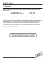
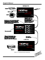
1.2 Product information
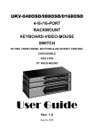
Figure 1 – C5-Series KVM local transmitter
Figure 2 – C5-Series KVM remote receiver
LINDY KVM Extender C5 Series
Installation and Use
page 8
English Manual
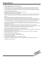
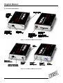
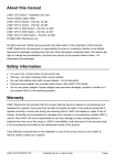
Figure 3 – C5-Series skew compensator unit
19 inch rack mount chassis
M3 pan head screw
for fixing security
plate to the rack
mount chassis
Rack securing plate
2 x M3 counter sunk
screws for fixing
security plate to C5
Series module
Figure 4 – C5-Series rack mount chassis and securing plates
LINDY KVM Extender C5 Series
Installation and Use
page 9
English Manual
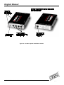
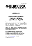
Figure 5 – C5-Series power distribution module
LINDY KVM Extender C5-Series
Installation and Use
page 10
English Manual
1.3 Package contents
The LINDY C5-Series KVM package (Part No. 39390)
Quantity
Description
1
1
1
1
1
8
KVM Extender C5 Junior local transmitter unit
KVM Extender C5 Junior remote receiver unit
Instruction manual
Power adaptor for the remote receiver unit
Cable to connect the local unit to a computer or KVM switch
Self-adhesive rubber feet
The LINDY C5-Series KVM remote receiver package contents (Part No. 39391)
Quantity
Description
1
1
1
4
KVM Extender C5 Junior remote receiver unit
Instruction manual
Power adaptor for the remote receiver unit
Self-adhesive rubber feet
The LINDY C5-Series skew compensation unit package contents (Part No. 39389)
Quantity
Description
1
1
4
Skew compensator unit
Instruction manual
Self-adhesive rubber feet
The LINDY C5-Series rack mount chassis (Part No. 39388)
Quantity
Description
1
1
Rack mount chassis
Instruction manual
LINDY KVM Extender C5-Series
Installation and Use
page 11
English Manual
The LINDY C5-Series rack mount securing and blanking plates
Quantity
Description
1
2
1
Rack mount securing plate
Counter-sunk screws for fixing the plate to the module
Pan head screw for fixing the plate to the rack mount chassis
The LINDY C5-Series rack mountable power distribution module package contents
(Part No. 39386)
Quantity
Description
1
1
4
1
1
2
1
Power distribution module
Power adaptor (5V, 2.5A)
Short patch cables
Instruction manual
Rack mount securing plate for power distribution module
Counter-sunk screws for fixing the plate to the PDM module
Pan head screw for fixing the plate to the rack mount chassis
LINDY KVM Extender C5-Series
Installation and Use
page 12
English Manual
2. Installation of the KVM Extender C5
2.1 What you will need
•
A category 5 (or better) twisted pair cable of the required length to connect the C5 KVM local and remote units
together. These cables contain 4 pairs of twisted wires. Specifications and recommended cable types are given
in appendix A. The C5 KVM supports cable lengths up to 200 metres. Structured wiring within buildings may
also be used together with suitable patch cables but the number of cable connections should be kept to a
minimum to maximise signal quality.
•
Cables to connect the C5 KVM local unit to your computer. A two metre connection cable is provided with the
C5 KVM. The cable may be extended using standard KVM extension cables. Cable specifications are given in
appendix A.
•
A monitor with a standard VGA/SVGA (15 pin) connector that will work when connected directly to your
computer. C5 KVM supports low and high resolution monitors.
•
A standard AT or PS/2 style keyboard. If you are using an AT keyboard with a 5 pin connector you may
connect this to the C5 KVM using a standard AT to PS/2 keyboard adaptor.
•
A PS/2 style two or three button Microsoft or Logitech compatible mouse or a Microsoft IntelliMouse
compatible mouse.
(The C5 KVM supports ‘Internet Mice’ that are compatible with the Microsoft IntelliMouse. These are fitted with
a wheel or other scroll control and sometimes have additional buttons. Examples are: Microsoft IntelliMouse,
Logitech Pilot Mouse+, Logitech MouseMan+, Genius NetMouse and Genius NetMouse Pro.)
•
A suitable mouse driver for your PC(s). Supported types are:
- PS/2 or RS232 two button mouse driver (any manufacturer).
- Microsoft mouse driver (including IntelliMouse).
- Logitech mouse driver (including two button, three button and wheel mouse)
Use of PS/2 and RS232 style mice with the C5 KVM - The mouse connections from the C5 KVM to PCs support
either a PS/2 or an RS232 mouse. The C5 KVM automatically converts from the PS/2 mouse commands to RS232
serial mouse commands. Serial mice types are selected by using an adaptor as described in appendix A. The C5
KVM will operate without a mouse connected if you do not wish to use one.
2.2 Mounting the C5 KVM
The C5 KVM has been designed to be used either on a desktop or mounted in a 19 inch rack. If you wish to use
the C5 KVM on a desktop then you will need to stick the self-adhesive rubber feet onto the underside of each C5
KVM module (one is supplied for each corner).
If the C5 KVM is to be mounted in a 19 inch rack then you will need the optional C5 series rack mounting chassis
(Part No. 39388) and a rack securing plate for each local module that you wish to rack mount (Part No. 39360)
The C5 KVM may also be mounted on a suitable vertical surface, such as the side of a desk, with the use of strong
Velcro strips.
LINDY KVM Extender C5-Series
Installation and Use
page 13
English Manual
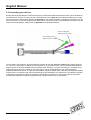
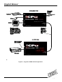
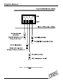
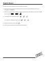
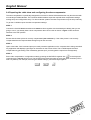
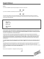
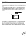
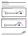
2.3 Connecting your devices
Ensure that the power adaptor is disconnected from the C5 KVM and that all the devices which are to be attached
are switched off. Connect your devices to the C5 KVM as shown in figure 6. Ensure that the cables are no longer
than the maximum cable lengths specified in appendix A. Any unused computer or peripheral connections can be
left unconnected. To connect computers with serial mouse connections and AT style keyboard connections you will
need to purchase adaptors. Please refer to appendix A for cable specifications.
PS/2 to AT keyboard
adaptor (Part No. 70130)
PS/2 to RS232 mouse
adaptor (Part No. 70058)
Connects to
C5 KVM local
transmitter
Cable supplied with C5 KVM
Connects to computer
The C5 KVM is now ready for use and will start to operate as soon the local and remote units are both powered
on. There is no requirement to switch the C5 KVM units on in any defined order. The C5 KVM local unit draws its
power from the connected computer via the keyboard cable. However, if you are connecting to a computer using
cables that are longer than 5 metres or are connecting to a lower powered device, such as some types of
keyboard/video/mouse switch, an optional power adaptor may be required. When using the optional power adaptor,
ensure that it is connected to the mains and powering the C5 KVM before you switch on the connected computers.
Under these circumstances, failure to switch the C5 KVM and computers on in the correct order can lead to the
mouse and/or keyboard not being recognised by the computers when they are switched on.
LINDY KVM Extender C5-Series
Installation and Use
page 14
English Manual
REMOTE
LOCAL
Figure 6 – A typical C5-KVM extender application
LINDY KVM Extender C5-Series
Installation and Use
page 15
English Manual
2.4 Configuring your PC (s)
Configure your PC in the same way that you would if your keyboard, mouse, speakers, microphone and monitor
were all connected directly to your PC, but bearing in mind the following points:
•
C5 KVM emulates Microsoft compatible serial, IntelliMouse and PS/2 mice, so ensure that your PC software is
configured for a Microsoft mouse of the correct type. Refer to the list of supported drivers in section 2.1.
•
C5 KVM supports VGA/SVGA/XGA/XGA2 type monitors, but does not support the automatic detection features
available with some ‘plug and play’ monitors and video cards. If you have this type of video card and monitor,
you should select the video mode manually instead of relying upon the automatic detection feature.
2.5 Configuring the C5 KVM
The C5 KVM is supplied in a default state that is suitable for most applications. By default, the automatic
compensation mode is selected. In this mode the video compensation amplifiers will be automatically adjusted to
suit the twisted pair cable whenever the C5 KVM is switched on. Some users may wish to manually fine tune the
video compensation because the perfect adjustment for any given length of cable is subjective and depends upon
personal preference. If manual compensation is selected then the video only needs to be compensated once
during setup as the compensation value is stored by the C5 KVM and retained even when the power is off.
The KVM Extender C5 Junior is configured using the following:
1. Option switches (see section 2.6)
The option switches on the side of the C5 KVM select automatic or manual video compensation mode and the
keyboard hotkey combination that is used to access video compensation / configuration mode. They also control
some other hardware related functions.
2. Video compensation / configuration mode (see section 2.7)
This mode is entered by typing the hotkey combination (selected using the option switches) on the keyboard
attached to the remote receiver. Once within video compensation / configuration mode you can adjust the video
compensation and select other options using the keyboard. The selected options are saved and stored in the
remote unit when you exit compensation / configuration mode.
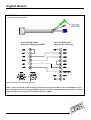
2.6 Setting the option switches
The option switches on the side of the C5 KVM remote and local units are used to select operating options. The
switches are continuously read by the C5 KVM and may be changed whilst the C5 KVM is powered on. The default
setting (all switches OFF) is suitable for most installations. The switches are shown in figures 7 and 8 and have
the following functions.
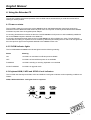
REMOTE unit – Switch 1
Set this switch to the OFF position for normal operation. This switch is used to set the C5 KVM remote unit into
upgrade mode so that new firmware can be downloaded into its flash program memory.
REMOTE unit – Switches 2 and 3
These switches select the hotkey combinations that are recognised by the C5 KVM. The chosen hotkey
combinations are used to enter compensation / configuration mode, lock the C5 KVM and disable the C5 KVM’s
video.
LINDY KVM Extender C5-Series
Installation and Use
page 16
English Manual
REMOTE unit – Switch 4
This switch is used to select the required video compensation mode. When the switch is in the OFF position,
automatic video compensation is selected. In automatic compensation mode, the C5 KVM will check the length of
twisted pair cable linking the local and remote units when it is powered on. It will then adjust the video
compensation amplifiers. In manual compensation mode, the video compensation setting may be adjusted by the
user.
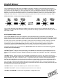
LOCAL unit – Switch 1
Set this switch to the OFF position for normal operation. This switch is used to set the C5 KVM local unit into
upgrade mode so that new firmware can be downloaded into its flash program memory.
LOCAL unit – Switch 2
This switch sets “transparent mode” operation. This mode is useful if the C5 KVM is to be used to linked to a KVM
switch. Cascaded KVM switches often use undocumented data to signal special conditions. In transparent mode
the C5 KVM will enable this undocumented data to be transferred between devices.
LOCAL unit – Switch 3
If this switch is set to the ON position then the remote unit will go directly into compensation / configuration mode
at power on. This enables a password locked remote unit to be reset. See section 4.6 for further details
LOCAL unit – Switch 4
This switch may be used to reset the local unit without disconnecting the power. In the OFF position the C5 KVM
will operate normally. In the ON position the C5 KVM will suspend all operation and reset itself to the power off
condition. Cycling the switch from the OFF position to the ON position and back to the OFF position again will
perform a reset without having to disconnect the computer connection cable.
LINDY KVM Extender C5-Series
Installation and Use
page 17
English Manual
Figure 7 – C5 KVM remote module option switches
LINDY KVM Extender C5-Series
Installation and Use
page 18
English Manual
Figure 7 – C5 KVM local module option switches
LINDY KVM Extender C5-Series
Installation and Use
page 19
English Manual
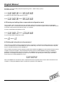
2.7 Setting the video compensation manually
The C5 KVM incorporates fine video compensation amplifiers to maximise the picture quality for any given length of
twisted pair cable. The C5 KVM can be set to automatically adjust the compensation amplifiers to match the cable
or you can adjust the amplifiers manually. Automatic compensation is enabled by setting option switch 4 on the
remote unit to the OFF position. Manual compensation is selected if switch 4 is in the ON position. The best video
compensation setting is often a matter of personal preference and so for the best picture quality we recommend
that you fine tune the amplifiers manually. To do this use the following procedure.
STEP 1
f
Enter video compensation mode by pressing the HOTKEYS together with
on the keyboard connected to the
remote receiver unit. The HOTKEYS are those that were set using the option switches (CTRL + SHIFT by default).
For example, assuming the default hotkeys, press these keys together:
b j f
STEP 2
The C5 KVM will now be in compensation adjustment mode. This is indicated by the NUM, CAPS and SCROLL
lock lights on your keyboard. These will flash in sequence at a rate that indicates the level of compensation: a slow
rate of flash indicates a compensation setting suitable for short lengths of twisted pair cable and a fast rate of flash
indicates a compensation setting that is suitable for long lengths of twisted pair cable.
LINDY KVM Extender C5-Series
Installation and Use
page 20
English Manual
Press
g to select no video compensation.
You should now see a ’fuzzy’ video picture on your monitor connected to the remote receiver unit.
STEP 3
You may now use the following keys to select the required video compensation.
g
Selects no video compensation
{
Increases video compensation to sharpen picture (coarse adjustment).
w
Increases video compensation to sharpen picture (fine adjustment).
}
Decreases the video compensation (coarse adjustment).
y
Decreases the video compensation (fine adjustment).
Various other keys may also be used to select operating options (see section 2.10)
As you change the video compensation setting you will see the sharpness of the picture change. The C5 KVM
calculates the required brightness automatically. You will need more video compensation for longer twisted pair
cable distances. Adjust the video compensation until you achieve the best picture. If you add too much
compensation then the picture may be lost. If this happens reduce the compensation to restore the picture.
The best compensation setting may be set using the following technique.
w until you observe white trailing edges on the right hand side of black text or graphics.
•
Press
•
Press and release
yuntil the white trailing edge just disappears.
LINDY KVM Extender C5-Series
Installation and Use
page 21
English Manual
STEP 4
Press
f to exit from compensation mode.
The C5 KVM saves the selected video compensation setting when you exit from compensation mode. This setting
is retained even when the power is off and so unless you change the twisted pair cable you will not need to readjust the compensation setting again.
If automatic video compensation mode has been selected using option switch 4 then the C5 KVM will automatically
calculate and store a new compensation setting the next time the remote unit is powered on or reset. To stop this
happening and keep you’re manually selected setting permanently, select manual compensation mode by setting
option switch 4 on the remote unit to the ON position.
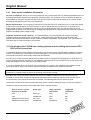
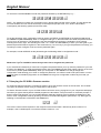
2.8 Performing special functions and selecting user configurable options
The C5 KVM supports a number of special functions and user-configurable options. These functions and options
are accessed whilst the C5 KVM is in video compensation / configuration mode.
f
To enter configuration mode press the HOTKEYS together with
on the keyboard connected to the receiver
unit. The HOTKEYS are those that were set using the option switches (CTRL + SHIFT by default).
For example, assuming the default hotkeys, press these keys together:
b j f
Functions and options are accessed by pressing a letter key followed by a number key followed by the RETURN
key. For example to run the function that resets the C5 KVM to its factory default settings:
Whilst within configuration mode press
F 8 f
The num, caps and scroll lock lights will indicate correct acceptance of the command as follows:
•
In compensation / configuration the num, caps and scroll lock lights will flash in sequence.
•
After pressing the first key of a command sequence the num, caps and scroll lock lights will all be illuminated.
•
After pressing the second key of a command sequence the num and caps lock lights will be on and the scroll
lock light will be off.
•
After pressing RETURN the command will have been accepted and the num, caps and scroll lock lights will go
back to flashing in sequence.
When you have finished selecting options, return to normal operation by pressing
LINDY KVM Extender C5-Series
Installation and Use
f
page 22
English Manual
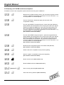
2.9 Summary of C5 KVM functions and options
Full details of each of the configuration options and their uses are given in section 4.
F1 f
F2 f
F3
F4
F8 f
M3 f
M4 f
Reports the C5 KVM’s firmware version. The connected computer must be
running an application that displays typed keys as screen characters – e.g.
a word processor or command prompt.
Force the C5 KVM to calculate and apply the automatic video
compensation setting.
For users with QWERTY keyboard layouts - reports the length difference
(skew) between the twisted pairs that are carrying the video colour signals
between the local and remote units. Also reports the best settings for a
skew compensation unit (if needed). The connected computer must be
running an application that displays typed keys as screen characters – e.g.
a word processor or command prompt.
(See section 6.4 for more details)
For users with AZERTY keyboard layouts - reports the length difference
(skew) between the twisted pairs that are carrying the video colour signals
between the local and remote units. Also reports the best settings for a
skew compensation unit (if needed). The connected computer must be
running an application that displays typed keys as screen characters – e.g.
a word processor or command prompt.
(See section 6.4 for more details)
Resets all user-configurable options to the default state (see 4.3)
(See section 5.1 for more details)
Selects “Microsoft” compatible mouse protocol signalling.
Selects “Logitech” compatible mouse protocol signalling.
(See section 5.2 for more details)
M6 f
Reset mouse function (See section 2.11)
M7 f
Reset IntelliMouse function (See section 2.11)
Pf {password} f
Sets a security password (See section 4.6)
Pf f
Clears the security password (See section 4.6)
LINDY KVM Extender C5-Series
Installation and Use
page 23
English Manual
2.10
Other useful installation information
PC boot up sequence - When your PCs are powered on they communicate with any attached keyboards and mice
and setup parameters required by the particular operating system. It is necessary for the C5 KVM to be attached
and powered on during this sequence so that it can give the required responses and keep track of all the modes
and settings requested by each of the connected PCs.
Mouse characteristics - do not unplug a PS/2 mouse connection from a PC whilst the PC is on. Due to the design
of PS/2 mice communications the mouse function on the PC will be lost and you will have to re-boot the PC to
regain normal operation. Unplugging the mouse from the C5 KVM will also cause it to stop operating when it is
plugged back in. RS232 mice can usually be unplugged and plugged back in provided that a mouse was connected
when the operating system initially booted.
Keyboard and mouse mode switching - The C5 KVM keeps a log of the keyboard and mouse mode and
resolution settings requested by the connected PC. These settings are automatically communicated to the
keyboard and mouse as required to ensure maximum software compatibility. The keyboard, num, caps and scroll
lock states are an obvious example of this process.
2.11 Hot plugging the C5 KVM into running systems and re-enabling disconnected CPU
PS/2 mouse connections
It is advisable to switch off the systems that are going to be connected to the C5 KVM before installation. However
if this is not possible then most systems can be hot plugged by using the C5 KVM’s mouse restoration functions.
The keyboard connection will normally restore itself automatically.
On many PCs, mouse movement will be lost if the PS/2 mouse is unplugged and plugged back in whilst the PC is
running. Mouse movement can then only be restored by rebooting the PC. This is because the mouse drivers only
setup and enable the mouse when the PC is initially booted.
If you have switched off your C5 KVM or you are attempting to ‘hot plug’ it into a system that is already running,
you may be able to restore lost mouse movement using the C5 KVM's mouse restoration functions.
Mouse restoration functions should be used with care as unpredictable results may occur if the wrong mouse type
is selected. If in doubt restore the mouse by powering down the PC normally.
Standard PS/2 mouse data uses a different data format to IntelliMouse data and so two reset functions are
provided on the C5 KVM. The type of data format expected by the PC depends upon the driver and the type of
mouse that was connected when the driver was booted. The following table may be used as a guide.
(Note that the mouse reset functions predict the likely mouse resolution settings but may not restore the speed or
sensitivity of the mouse exactly as they were when the PC originally booted).
Type of mouse / system
Driver type
Connected at bootup
PS/2
PS/2 only
Likely expected
Suggested
data format
restoration
PS/2
M6
PS/2
IntelliMouse
PS/2
M6
IntelliMouse/ KVM Switch
PS/2 only
PS/2
M6
IntelliMouse/ KVM Switch
IntelliMouse
IntelliMouse
M7
LINDY KVM Extender C5-Series
Installation and Use
page 24
English Manual
To restore lost mouse movement on a CPU connected to the C5 KVM:
1) Ensure that the video picture of the CPU that has lost its mouse movement is displayed on the monitor
connected to the remote unit.
2) Enter the configuration mode by pressing ‘HOTKEYS’ and RETURN on the keyboard connected to the remote
unit. For example:
b j f
3) To restore a PS/2 mouse connection press:
M 6 f
Or, to restore an IntelliMouse connection press:
4) Exit from configuration mode by typing:
M 7 f
f
5) Test the mouse movement by moving the mouse a short distance.
LINDY KVM Extender C5-Series
Installation and Use
page 25
English Manual
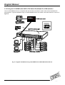
2.12 Using the C5 KVM/R with LINDY CPU Switch Dual/Quad Pro KVM switches
The C5 KVM remote receiver is compatible with the extender ports fitted to LINDY CPU Switch Dual/Quad Pro
KVM switches. A typical installation using a C5 KVM remote receiver and LINDY CPU Switch Dual Pro is shown in
figure 9.
Fig. 9 - A typical installation using a C5 KVM/R and a LINDY Switch Dual Pro 8
LINDY KVM Extender C5-Series
Installation and Use
page 26
English Manual
3. Rack mounting C5 Series products in the 19 inch rack mount chassis
3.1 Mounting C5 Series modules into the rack mount chassis
C5 Series products may be rack mounted in the C5 Series 19 inch rack mounting chassis (Part No. 39388). Up to
16 C5 Series modules may be mounted in each 2U chassis. You will need to purchase a rack securing plate for
each module that you wish to mount in the chassis. Part numbers for the rack securing plates are as follows:
C5 Series module
C5 KVM local transmitter
C5 Skew compensator unit
Rack securing plate
39360
39369
Each rack securing plate is provided with two counter-sunk screws which may be used to attach the securing plate
to the C5 Series module.
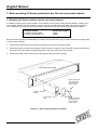
1. Attach the securing plate to the module using the two counter-sunk screws provided.
2. Offer the assembly into the rack mounting chassis as shown in figure 10 and locate the module so that the two
pan head screws fit inside the mating fixing holes in the base of the rack mount chassis.
3. Use the pan head screw to attach the securing plate to the rack mount chassis.
19 inch rack mount chassis
M3 pan head screw
for fixing securing
plate to the rack
mount chassis
C5 Series
module
Rack securing
plate
M3 pan head screw
for fixing securing
plate to the rack
mount chassis
Figure 10 – Rack mounting C5 Series modules
LINDY KVM Extender C5-Series
Installation and Use
page 27
English Manual
3.2 Installing and using the rack mountable power distribution module
If you are rack mounting multiple C5 KVM/R units then it is undesirable to use separate power supplies for each of
these modules. The C5 Series power distribution module (Part no. 39386) may be used to power these units and
create a neater installation. The power distribution module enables you to power up to 4 C5 KVM/R units from the
single power adaptor supplied with the power distribution module. Short patch cables are provided with the power
distribution module to connect its four power outlets to the rack mounted C5 KVM/R modules. A power indicator on
the power distribution module confirms that power is available. The power distribution module’s power outlets are
designed to provide 500mA of current at 5 volts.
Patch cables are available to enable the local transmitter to be connected to the power distribution module –
Please contact your supplier.
3.3 Blanking plates for the 19 inch rack mount chassis
The 19 inch rack mount chassis may be populated with any mixture of C5 Series modules. Each chassis will house
up to 16 modules. If the chassis is not fully populated then unused mounting positions (slots) may be left empty.
In some installations it is necessary to ensure that there are no gaps in the front face of the chassis assembly so
that the airflow and cooling characteristics of the rack are maintained. In these installations, unused slots may be
filled (blanked off) using C5 Series blanking plates. These are available to blank off one or four slots. Part numbers
are:
39361
39362
LINDY KVM Extender C5-Series
Single slot blanking plate
Quad slot blanking plate
Installation and Use
page 28
English Manual
4. Using the Extender C5
This section explains the general operation of the C5 KVM. We recommend that you read this section before
starting to use the product.
4.1 Power on status
The C5 KVM is ready for use as soon as the remote receiver and local transmitter have been powered on.
Remember that the local transmitter draws its power from the computer via the keyboard cable and the remote
unit draws its power from the supplied power adaptor.
If a security password has not been set then the C5 KVM remote unit will power on and immediately establish a
link to the remote computer attached to the local unit.
If a security password has been set then the C5 KVM remote unit will not display any video. The C5 KVM will
indicate that it is waiting for a password to be entered by alternately illuminating the num and scroll lock lights and
then the caps lock light on the keyboard attached to the remote receiver unit.
4.2 C5 KVM indicator lights
The C5 KVM local and remote unit indicator lights have the following meaning:
Status
Meaning
ON
C5 KVM is on and there is sufficient power available
OFF
C5 KVM is off and sufficient power is not available
FLASHING
C5 KVM is sending or receiving keyboard or mouse data
SLOW FLASHING
C5 KVM is in upgrade mode
4.3 Keyboard NUM, CAPS and SCROLL lock indicators
The C5 KVM uses the keyboard NUM, CAPS and SCROLL lock lights to indicate various operating conditions as
follows:
NUM, CAPS and SCROLL lock lights flash in sequence
LINDY KVM Extender C5-Series
Installation and Use
page 29
English Manual
The C5 KVM flashes the NUM, CAPS and SCROLL lock lights in sequence on the keyboard connected to the
remote unit to indicate that the C5 KVM is in video compensation / configuration mode. The NUM lock light comes
on first with CAPS and SCROLL off. Then the CAPS lock comes on with NUM and SCROLL off and finally the
SCROLL lock comes on with NUM and CAPS off. The rate of flashing indicates the level of video compensation
applied by the video compensation amplifiers. A slow flash rate indicates a small amount of compensation (short
twisted pair cable distance). A fast flash rate indicates a greater level of video compensation for longer cables.
NUM and SCROLL lock flash alternately with CAPS lock
The C5 KVM alternately flashes NUM and SCROLL lock and then CAPS lock on the keyboard attached to the
remote unit to indicate that the C5 KVM is currently locked and is awaiting a password to be entered by the user to
unlock the C5 KVM.
4.4 Keyboard hotkey control
The C5 KVM remote unit may be set to respond to various keyboard hotkey combinations. These keyboard
hotkeys are selected using the option switches on the side of the C5 KVM remote unit (see section 2.6). Keyboard
hotkeys may be used to switch off the video, lock the C5 KVM and enter video compensation / configuration mode.
All of the hotkey control commands are invoked by holding down the two hotkeys and then pressing a command
key. By default, the two hotkeys are ‘CTRL’ and ‘SHIFT’; although other combinations can be selected by
reconfiguring the hotkeys (see section 2.6). Once the hotkey command has been activated you will need to
release the hotkeys and the command key before a new hotkey command is accepted by the C5 KVM.
The hotkey commands are summarised below (IMPORTANT NOTE: the numbers on the numeric keypad do
not form part of a valid hotkey):
‘HOTKEYs’ and ‘0’ – switches off the video signal on the remote unit and disconnects the keyboard and mouse
from the computer that they are currently controlling. This will cause some monitors to go into standby mode or
switch off. The video signal can be re-enabled by selecting a computer using ‘HOTKEYs’ and ‘TAB’ or ‘HOTKEYs’
and ‘1’.
‘HOTKEYs’ and ‘L’ - Disconnects the C5 KVM remote’s keyboard and mouse from the computer that they are
controlling. The video signal is switched off. If a password has not been set then the C5 KVM can be re-enabled by
using ‘HOTKEYs’ and ‘TAB’ or ‘HOTKEYs’ and ‘1’. If a password has been set then the C5 KVM will alternately
flash the NUM and SCROLL and then the CAPS lock lights on the keyboard connected to the remote unit. This
indicates that a valid password must be entered to unlock the C5 KVM. Simply type the same key combination as
was set during configuration (see section 4.6) followed by the RETURN key. Note - if anyone has typed at the
keyboard whilst in secure mode, it will be necessary to press RETURN first to clear the invalid password, then type
the valid password followed by RETURN again.
‘HOTKEYs’ and ‘1’ - selects the remote computer attached to the local unit.
‘HOTKEYs’ and ‘TAB’ – selects the remote computer attached to the local unit.
‘HOTKEYs’ and RETURN – Enters video compensation / configuration mode.
LINDY KVM Extender C5-Series
Installation and Use
page 30
English Manual
Examples of common hotkey sequences (assuming CTRL + SHIFT hotkey option):
To lock the C5 KVM:
Press
bjL release Lbj
To disable the video signal and blank the monitor:
Press
bj0 release 0bj
4.5 Entering and exiting video compensation/configuration mode
The C5 KVM’s video compensation and user selectable options and functions are accessed in compensation /
configuration mode. To enter this mode press the selected hotkey combination together with the RETURN key and
to exit this mode press the RETURN key again. For example:
To enter compensation/configuration mode:
Press
bjf release fbj
To exit compensation/configuration mode:
Press
f release f
4.6 Setting and using the security password
There are many situations where unrestricted access to computers or sensitive information needs to be controlled.
In such circumstances, the C5 KVM local unit may be locked away in a room or secure cabinet and the computer
may be controlled remotely from the remote unit.
The C5 KVM incorporates a security password system that enables the remote unit to be locked so that the secure
computer cannot be controlled. Once a password has been set the C5 KVM remote unit may be disabled by
pressing the hotkeys together with the L (lock) key. The remote unit may only then be unlocked by entering the
password. For example if the hotkeys are set to CTRL and SHIFT then pressing the following key combination
would cause the C5 KVM remote unit to lock –
bjL
When the remote unit is locked the video is switched off and the keyboard and mouse are disconnected from the
computer. Locking the remote unit does not affect the operation of the local unit.
LINDY KVM Extender C5-Series
Installation and Use
page 31
English Manual
To unlock the C5 KVM remote unit enter the password followed by the RETURN key e.g. –
PASSWORDf
NOTE - The password consists of a combination of key strokes rather like the code to a safe. The key strokes are
not case sensitive and can include all the keys on the keyboard (except CTRL, ALT, SHIFT and ENTER).
Consequently the following 'password' would be valid –
oFREDg
To set the password, enter configuration mode by typing ‘HOTKEYS’ and RETURN on the keyboard attached to
the remote unit (see section 2.8). When in configure mode type ‘P’ then RETURN. Now enter the password which
may be up to 40 characters. The password is not case sensitive and can be any combination of key strokes,
including the function keys, but excluding the CTRL, ALT, SHIFT and RETURN keys. When you have typed in your
password press RETURN to register it in the stored memory. Do not worry if you type the password incorrectly, you
can always re-enter configure mode and set the password again.
For example, to enter OPENUP as the password type the following whilst in configuration mode –
PfOPENUPf
What to do if you’re C5 KVM is locked and you have lost or forgotten the password
If your C5 KVM is locked and you have lost or forgotten the password then you may clear the password if you have
access to the local unit. To clear the password power down the remote unit and switch option switch 3 on the local
unit to the on position (see section 2.6). When you next power on the remote unit it will go straight into
configuration mode allowing you to clear or change the password. You will then need to set option switch 3 on the
local unit back to its default (off) position or the remote unit will go into configuration mode every time that you
switch it on.
4.7 Querying the C5 KVM’s firmware version
For technical support purposes it is sometimes useful to know the firmware version of the C5 KVM. The C5 KVM
can report its firmware version using a configuration mode function.
To find the firmware version of your C5 KVM will first need to be running a program on your computer that displays
text when you type at the keyboard. Suitable programs are text editors, word processors or command prompts. It
doesn’t matter what program you use provided that the characters typed in at the keyboard are displayed on the
screen. Enter configuration mode by pressing ‘HOTKEYs’ and RETURN together (see section 4.5). Now type the
following on the keyboard connected to the remote unit:
F1 f
The version number will be reported on the computer screen as the letter V followed by three numbers. For
example, it the C5 KVM reports V118 the the firmware version is 1.18.
LINDY KVM Extender C5-Series
Installation and Use
page 32
English Manual
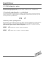
5. C5 KVM Configuration options
All the options described in this section are entered in C5 KVM’s configuration mode - see section 4.5 for
instructions on entering configuration mode.
5.1 Resetting all configuration options to their default state
To reset all the C5 KVM’s configuration options to the default state press the following whilst within configuration
mode. By resetting all the configuration options to their default state you will also clear the password but you will
not change the video compensation setting.
F8 f
5.2 Selecting a mouse signaling protocol
Most mouse drivers are compatible with Microsoft mice and so a “Microsoft compatible” mouse signaling protocol is
suitable for most systems. In some installations, Logitech mouse drivers may disable the action of the mouse
buttons when used with the “Microsoft compatible” signaling protocol implemented by the C5 KVM. To solve this
problem select the “Logitech compatible” mouse signaling protocol.
M3 f - Sets “Microsoft compatible” mouse protocol signalling.
M4 f – Selects “Logitech compatible” mouse protocol signalling.
LINDY KVM Extender C5-Series
Installation and Use
page 33
English Manual
6. Configuring and using the skew compensator
6.1 What is the skew compensator and why is it needed?
The skew compensator corrects the video colour split that is sometimes introduced when a video picture is
transmitted over twisted pair cables. Twisted pair cables are typically constructed using four pairs of twisted wires.
Each of the pairs of wires are normally twisted at slightly different rates to reduce the crosstalk between the pairs.
This is highly advantageous for digital data transmission but can sometimes cause a problem when the cables are
used to carry video signals. The reason for this is that three different pairs are used to carry the red, green and blue
colour components of the video picture. If the length of cable used is long enough and the twist rates differences
between the twisted pairs are large enough then there will be a significant length difference between the wires that
carry the different video colour signals. This means that the colour signals will arrive at the C5 KVM remote
receiver at different times and the colours on the video picture will appear to split causing the picture clarity to be
reduced. A typical characteristic of this colour split effect is a red, green or blue shadow around bright white
objects. The skew compensator removes this colour split by deliberately delaying some of the colour signals so that
all the signals arrive at the remote receiver at the same time.
6.2 Can I predict if a skew compensator will be needed?
It is remarkably difficult to predict if a skew compensator will be needed because twisted pair cables from different
manufacturers have substantially different characteristics. Although Category 5e and Category 6 cables typically
have larger twist rate differences than Category 5 cables there are several types of Category 5e and Category 6
cables with low twist rate differences. With similar specification cables, the colour split introduced by one cable may
be four times the colour split introduced by another apparently similar cable. What’s more, colour split effects
become more noticeable at higher screen resolutions. The reason for this is that the pixel time on higher resolution
screens is shorter and so a given colour delay represents more pixels.
As a general rule, colour signal skew is more of a problem with higher specification cables (i.e. Cat 6 / Cat 5e),
longer cable lengths and higher screen resolutions. For example, an installation running a screen resolution of
1024 x 768 over 50 metres of Cat 5 cable will probably exhibit minimal colour split whereas an installation running a
screen resolution of 1600 x 1200 over 100 metres of Cat 6 cable will probably exhibit some noticeable colour split.
6.3 Correcting the colour split
If you have a noticeable problem with colour split then you have several choices. You could use a shorter length of
twisted pair cable or a different type of twisted pair cable. Alternatively you could reduce the screen resolution that
you are using. If none of these are possible then the colour split may be corrected using the C5-Series skew
compensator. The skew compensation unit is inserted into the twisted pair cable connection between the local
transmitter and remote receiver as shown in figure 11.
LINDY KVM Extender C5-Series
Installation and Use
page 34
English Manual
REMOTE
LOCAL
Figure 11 – Installing the skew compensator
LINDY KVM Extender C5-Series
Installation and Use
page 35
English Manual
6.4 Reporting the cable skew and configuring the skew compensator
The skew compensator is specifically designed for use with C5 Series KVM extenders but may also be used with
most analogue KVM extenders. The C5 Series KVM extenders report the required skew compensator settings
making setup and configuration easy. For other extender systems the skew compensator may be setup manually.
To get the C5 KVM to report the skew compensator settings:
STEP 1
Connect the C5 KVM local transmitter and remote receiver together with the twisted pair cable(s) that you are
going to use. If you already have a skew compensator then connect this as shown in figure 11 but set all the
switches to the OFF position.
STEP 2
Ensure that the video picture is correctly compensated (see section 2.7). If the video picture is not correctly
compensated then the reported skew settings may be less accurate.
STEP 3
Open a text editor, DOS command prompt or word processor application on the computer that is being controlled.
Any application that displays typed keys as characters on the screen will do. The C5 KVM reports the skew
compensation by generating a set of faked key presses (as if you had typed the report from the keyboard).
STEP 4
f
Enter video compensation / configuration mode by pressing the HOTKEYS together with
on the keyboard
connected to the remote receiver unit. The HOTKEYS are those that were set using the option switches (CTRL +
SHIFT by default). For example, assuming the default hotkeys, press these keys together :
b j f
LINDY KVM Extender C5-Series
Installation and Use
page 36
English Manual
STEP 5
If you have a QWERTY keyboard layout (English, German etc.) then press:
F 3
If you have an AZERTY keyboard layout (French) then press:
F 4
The screen will go blank for a few seconds whilst the C5 KVM applies measurement signals to the cable to
measure the length differences between the twisted pairs. When the picture is restored a report similar to that
shown below will be generated:
SKEW REPORT
RED +0.5M
GREEN +1.0M
BLUE +0.0M
SWITCHES ON
A3 B4
The first section of the report indicates the length differences between the twisted pairs that are carrying the red,
green and blue signals. One of the colours will have a reported length difference of 0.0M – this colour is carried by
the SHORTEST twisted pair. The other reported lengths indicated the difference between the twisted pair used to
carry the colour signal and the shortest twisted pair.
The second section of the report indicates the skew compensator switches that should be switched ON to
compensate for the twisted pair length differences indicated by the report. All other switches should be OFF. You
will see that each of the switches is constructed using 4 individual sliders. To set the switch ON, all four sliders
must be moved to the ON position. To set the switch OFF, all four sliders must be set to the OFF position. The
example skew report shown above indicates that switches A3 and B4 should be ON and all the other switches
should be OFF.
To compensate for colour split, setup the skew compensator as indicated and insert it in the twisted pair cable run
between the local transmitter and remote receiver as shown in figure 11. You will need a short patch lead to do
this.
The settings that are reported represent the compensation required to remove the skew that is introduced by the
twisted pair cable. There is sometimes some colour skew present on video signals being generated by the
computer. Consequently the video picture can sometimes be slightly improved by using skew compensator settings
that are slightly different to those reported (see section 6.5).
STEP 6
Exit from the compensation / configuration mode by pressing:
f
LINDY KVM Extender C5-Series
Installation and Use
page 37
English Manual
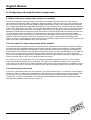
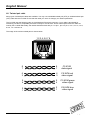
6.5 Setting up the skew compensator manually
If the skew compensator is to be used with a KVM extender that does not have a skew setting reporting feature
then you will need to setup the skew compensator manually. To do this you will first need to determine which of the
switch banks controls which of the colours (on all C5 Series products, switch bank A is BLUE, B is RED and C is
GREEN).
To determine which switch bank controls the delay of which colour you must first install the skew compensator as
shown in figure 11. Set all the switches to the OFF position. Now set all the switches in one bank (e.g. A1 to A4) to
the ON position and observe the change to the video picture. The delayed colour should appear as a shadow on
the right hand side of white objects that are on a dark background. This shadow may best be observed of you have
a picture with white objects set against a black background. For example, if you create a picture similar to that
shown below in a drawing package such as Paint then the delayed colour will be seen on the right hand side of the
white square.
Once you have determined which set of switches controls which colour you can switch all the switches OFF and
observe the picture. Remember that the picture is made up from red, green and blue colour signals. Use a test
pattern similar to that shown above and observe the component colour that is most delayed (i.e. the one that
appears as a shadow after a white image on a black background). Leave all the switches associated with this
colour in the OFF position and start to add delays to the OTHER colours by setting some of their associated
switches to the ON position. Observe the changes to the picture after you change the switches. Switches 1 and 2
each introduce a 10 nanosecond delay. Switch 3 introduces a 5 nanosecond delay and switch 4 introduces a 2.5
nanosecond delay.
A process of trial and error is required to find the best switch settings.
LINDY KVM Extender C5-Series
Installation and Use
page 38
English Manual
7. Upgrading the Extender C5’s flash memory
The C5 KVM uses flash memory technology which enables the firmware code to be upgraded by the user.
Upgrades are performed by using a PC program to download the new firmware via the keyboard connection. The
local transmitter and remote receiver both contain microprocessors with flash rewritable program memory. They
may be independently upgraded but we highly recommend that you always upgrade both the local and remote
units when performing an upgrade.
To perform a flash upgrade you will need to create an MS-DOS boot disk. This boot disk is used to run the upgrade
program automatically without the need for keyboard control. From DOS systems, a boot disk can be created using
the DOS FORMAT command (e.g. FORMAT A: /S). For Windows 95 and 98, DOS boots disks can be created in a
similar manner. For other versions of Windows refer to Windows Help for instructions. For example, a DOS disk
can be created from Windows XP by selecting My Computer, right clicking on the A disk icon, selecting Format
and then selecting Create an MS-DOS startup disk.
To upgrade the C5 KVM’s firmware
STEP 1
Create an MS-DOS boot disk using a blank floppy disk.
STEP 2
Download the latest firmware upgrade files from the LINDY website (www.lindy.com). The firmware upgrade is
available as a compressed ZIP file containing the following files (xxx is the version number of the firmware – for
example 108 is version 1.08).
XKVMxxx.EXE
XREMxxx.HEX
XLOCxxx.HEX
AUTOEXEC.BAT
The download program (e.g. XKVM108.EXE) – this automatically selects the firmware to
use by detecting the unit that is connected during download.
The firmware file for the remote receiver (e.g. XREM108.HEX)
The firmware file for the local transmitter (e.g. XLOC108.HEX)
The autoexec file for the DOS boot disk that automatically runs the upgrade file
(XKVM.EXE)
Copy these four files to the root directory of the MS-DOS boot disk (you will need to overwrite the AUTOEXEC.BAT
file that is currently on the DOS disk).
LINDY KVM Extender C5-Series
Installation and Use
page 39
English Manual
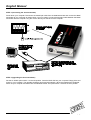
STEP 3 (connecting the local transmitter)
Power down your computer. Disconnect the twisted pair cable from the local transmitter and connect the local
transmitter to your computer as shown below. You only need to connect the keyboard cable between the local
transmitter and the computer. Plug the monitor directly into the back of the computer.
STEP 4 (upgrading the local transmitter)
Set the C5 KVM’s option switch 1 to the ON position. Insert the DOS disk into your computer’s floppy drive and
power on your computer. The upgrade should be performed automatically. When the upgrade has completed,
switch off your computer and disconnect the local transmitter. Set option switch 1 back to the OFF position.
LINDY KVM Extender C5-Series
Installation and Use
page 40
English Manual
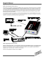
STEP 5 (connecting the remote receiver)
Power down your computer. Power down the remote receiver. Disconnect the twisted pair cable from the remote
receiver. Do not power any of the devices yet. Connect the remote receiver to your computer as shown below.
To do this you will need a keyboard cable (6 pin mini-DIN male to 6-pin min-DIN male, all lines connected). If you
have a KVM switch product the chances are that you will have one of these connecting the switch to a computer.
You only need to connect the keyboard cable between the remote receiver and the computer. Plug the monitor
directly into the back of the computer.
This configuration might seem strange to you because the keyboard port on the C5 KVM remote receiver would
normally be connected to a keyboard and not to a computer keyboard port. The product is designed to reverse the
operation of the keyboard port during the flash upgrade process.
STEP 6 (upgrading the remote receiver)
Set the C5 KVM’s option switch 1 to the ON position. Power the C5 KVM remote receiver by connecting the power
adaptor. Insert the DOS disk into your computer’s floppy drive and power on your computer. The upgrade should
be performed automatically. When the upgrade has completed, switch off your computer and disconnect the
remote receiver. Set option switch 1 back to the OFF position.
Reconnect the upgraded C5 KVM as shown in figure 6.
LINDY KVM Extender C5-Series
Installation and Use
page 41
English Manual
Appendix A. Cable and connector specifications
IMPORTANT NOTE
The maximum cable lengths supported vary widely between devices and cables. It may be possible to use
cables that are longer than those specified below with certain PCs and peripherals but this cannot be
guaranteed. If you experience problems try using shorter cables.
A1. Keyboard, monitor and mouse connections
All of these devices plug directly into the relevant ports of the C5 KVM. If you use an AT style keyboard you will
need an AT (5 pin DIN female) to PS/2 (6 pin mini-DIN male) converter.
Cable specification for connections from the remote unit to the keyboard, monitor and mouse
Ideally keyboard, monitor and mouse cables should not be longer than 10 metres.
Many keyboards and mice will also operate at distances of 20 metres but this cannot be guaranteed. If you are
using a monitor extension cable then you should ensure that this is a high quality tri-coax type.
LINDY KVM Extender C5-Series
Installation and Use
page 42
English Manual
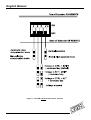
A2. Computer connections
Cables for connection to PCs:
When used without the auxiliary power adaptor, cables to PCs may be up to 5 metres long. With the optional power
adaptor the cables may be extended up to 30 metres using standard extension cables. Video extension cables
should be good quality with a coaxial construction. Please contact your supplier if you have any questions.
C5 KVM Local module connector cable
Connects to PC
Connects to C5 KVM
Local module
Mouse (6 pin)
Keyboard (6 pin)
Video (15 pin)
Adaptors
LINDY PS/2 Keyboard to AT Port adaptor (Part No. 70130) If your PC has a 5-pin DIN AT style
keyboard connector you will need a PS/2 to AT keyboard adaptor 6-pin mini-DIN female to 5-pin DIN male.
PS/2 to AT
Keyboard adaptor
(Part No. 70130)
LINDY KVM Extender C5-Series
Installation and Use
page 43
English Manual
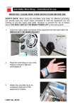
LINDY PS/2 Mouse to Serial Port adaptor This is required if you wish to connect a computer that has a
9-pin serial mouse connection:
PS/2 to RS232
mouse adaptor
(Part No. 70058)
6 pin mini-DIN female
plugs into cable from C5 KVM
9 pin mini-DIN female
plugs into PC serial port
Cables should be no longer than 30 metres.
NOTE - There are several common wiring specifications for 6-pin mini-DIN to 9-pin serial adaptors. If you
have an adaptor that has been supplied with a mouse it may have a completely different internal wiring to
that shown above and may not be compatible with the C5 KVM
LINDY KVM Extender C5-Series
Installation and Use
page 44
English Manual
A3. Twisted pair cable
Many types of twisted pair cables are available. You may use unshielded twisted pair (UTP) or shielded twisted pair
(STP) cable with the C5 KVM. Ensure that the cable you use is of Category 5 or better specification.
The C5 KVM uses the following pairs on the twisted pair RJ45 jack connector. If your cable is terminated for
networking use then it will probably be wired correctly for the C5 KVM. All four twisted pairs within the cable are
used by the C5 KVM. Electrically, the cables should be wired with pin 1 to pin 1, pin 2 to pin 2, 3 to 3, 4 to 4, 5 to 5,
6 to 6, 7 to 7 and 8 to 8.
The usage of the various twisted pairs is shown below:
12345678
8
7
8
7
C5 KVM
data signal
6
3
6
3
C5 KVM red
video signal
5
4
5
4
C5 KVM green
video signal
2
1
2
1
C5 KVM blue
video signal
LINDY KVM Extender C5-Series
Installation and Use
page 45