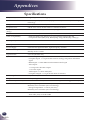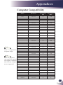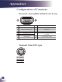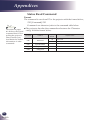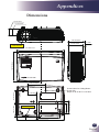
1
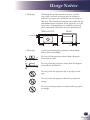
Multimedia Projector MODEL PDG-DSU30 Owner's Manual Table of Contents Table of Contents Appendices Troubleshooting.................................................... 33 Usage Notice Precautions............................................................. 2 Replacing the lamp............................................... 38 Specifications....................................................... 40 Computer Compatibility........................................ 41 Introduction Package Overview.................................................. 6 Configurations of Terminals.................................. 42 Terminal : Analog RGB (Mini D-sub 15 pin)....... 42 Terminal : Mini DIN 3-pin................................... 42 Product Overview................................................... 7 Connection Ports................................................. 8 Remote Control.................................................... 9 Remote Control Battery Installation................... 11 Remote Control Operating Range..................... 11 Serial Control Interface......................................... 46 Operation........................................................... 46 Functional Execution Command........................ 47 Status Read Command..................................... 48 Product Features.................................................... 5 Regulation & Safety Notices................................. 43 Dimensions........................................................... 49 Installation Connecting the Projector...................................... 12 Connect to Computer/Notebook........................ 12 Connect to Video............................................... 13 Powering On/Off the Projector.............................. 14 Powering On the Projector................................. 14 Powering Off the Projector................................. 15 Warning Indicator............................................... 16 Adjusting the Projected Image.............................. 17 Adjusting the Height of Projector Image............ 17 Adjusting the Projector Zoom and Focus........... 18 Adjusting Projection Image Size........................ 18 User Controls On Screen Display................................................ 19 How to operate.................................................. 19 IMAGE............................................................... 20 IMAGE |Advanced............................................. 22 IMAGE | Advanced | Color................................. 23 IMAGE | Advanced |Input.................................. 23 SCREEN............................................................ 24 SETTING | Language........................................ 26 SETTING........................................................... 26 SETTING | Signal.............................................. 28 SETTING | Advanced........................................ 29 OPTIONS........................................................... 30 OPTIONS | Advanced........................................ 31 OPTIONS | Lamp Settings................................. 32 1 English English Usage Notice Precautions Follow all warnings, precautions and maintenance as recommended in this user’s guide to maximize the life of your unit. 2 English ■ Warning- This apparatus must be earthed. ■ Warning- Do not look into the projector’s lens when the lamp is on. The bright light may hurt your eyes. ■ Warning- To reduce the risk of fire or electric shock, do not expose this projector to rain or moisture. ■ Warning- Please do not open or disassemble the projector as this may cause electric shock. ■ Warning- When replacing the lamp, please allow unit to cool down, and follow all replacement instructions.. ■ Warning- This projector will detect the life of the lamp itself. Please be sure to change the lamp when it shows warning messages. ■ Warning- Reset the “Lamp Counter Reset” function from the on-screen display “Options|Lamp Settings” menu after replacing the lamp module (refer to page 32). ■ Warning- When switching the projector off, please ensure the cooling cycle has been completed before disconnecting power. Allow 120 seconds for the projector to cool down. ■ Warning- Do not use lens cap when projector is powered on. ■ Warning- Turn on the projector first and then the signal sources. ■ Warning- When the lamp reaches the end of its life, it will burn out and may make a loud popping sound. If this happens, the projector will not turn back on until the lamp module has been replaced. To replace the lamp, follow the procedures listed under “Replacing the Lamp”. Usage Notice ■ Warning- Allowing the proper amount of space on the top, sides, and rear of the projector cabinet is critical for proper air circulation and cooling of the unit. The dimensions shown here indicate the minimum space required. If the projector is to be built into a compartment or similarly enclosed, these minimum distances must be maintained. SIDE and TOP REAR 1.5' (50 cm) 3' (1 m) ■ Warning- 1.5' (50 cm) 1.5' (50 cm) Avoid positioning the projector as described below when installing. Do not roll the projector more than 9 degrees from side to side. Do not pitch the projector more than 15 degrees from above and below. Do not point the projector up to project an image. Do not point the projector down to project an image. Do not put the projector on either side to project an image. 3 English English Usage Notice Do: ■ T urn off the product before cleaning. ■ Use a soft cloth moistened with mild detergent to clean the display housing. ■ Disconnect the power plug from AC outlet if the product is not being used for a long period of time. Do not: ■ Block the slots and openings on the unit provided for ventilation. ■ U se abrasive cleaners, waxes or solvents to clean the unit. ■ Use under the following conditions: - Extremely heat, cold or humidity. - In areas susceptible to excessive dust and dirt. - Near any appliance generating a strong magnetic field. - In direct sunlight. 4 English Introduction Product Features This product is a SVGA single chip 0.55” DLP® projector. Outstanding features include: ■True SVGA, 800 x 600 addressable pixels ■ Single chip DLP® technology ■NTSC3.58/NTSC4.43/PAL(B/D/G/H/I/M/N)/ ■Multi-Auto functions: Auto detection, Auto image and ■ Full function remote control ■ User friendly multilingual on screen display ■Advanced digital keystone correction and high quality ■Built-in mono 2-Watt speaker. ■UXGA, WXGA, SXGA+, SXGA, XGA compression and ■ Macintosh compatible SECAM (B/D/G/K/K1/L) and SDTV(480i/576i), EDTV(480p/576p), HDTV(720p/1080i/1080p) compatible Auto saving the adjustments full screen image re-scaling VGA re-sizing 5 English English Introduction Package Overview This projector comes with all the items shown below. Check to make sure your unit is complete. Contact your dealer immediately if anything is missing. CR2025 3V N ot e Due to the difference in applications for each country, some regions may have different accessories. Projector with lens cap Wireless Remote Control Power Cable VGA Cable Cable AC Power Cable (for U.S.A.) 42.00105G011 AC Power Cable (for Continental Europe) 42.00120G011 AC Power Cable (for UK) 42.00110G011 VGA Cable 42.00200G005 Documentation: CD-ROM User’s Manual Quick Reference Guide 6 English Factory code Battery Introduction Product Overview 4 1 7 2 3 4 7 5 6 8 9 Air Flow 1. 2. 3. 4. 5. 6. 7. 8. 9. ON/STAND-BY button and LED indicator Remote Sensor Zoom Ring Ventilation (inlet) Speaker Focus Ring Ventilation (outlet) Lens Lens Cap 7 English English Introduction Connection Ports 1 2 3 4 5 6 7 1.COMPUTER IN/COMPONENT IN Connector 2. S-VIDEO IN Connector 3. VIDEO IN Connector 4. SERVICE Port 5.MONITOR OUT Connector 6. AUDIO IN Jack 7. AC IN 8 English 8 8. KensingtonTM Lock Introduction Remote Control 1 N ot e 2 11 S 3 LT C R 20 25 Before using the remote control for the first time, remove the transparent insulation tape. See page 11 for battery installation. O 3V 4 12 13 5 14 15 6 7 16 17 8 18 9 10 10 N ot e You can only turn the projector on/off with ON/STAND-BY button on the projector. You can operate all of the functions of the projector via the remote control. Make sure not to lose the remote control. 19 1 Infrared transmitter Sends signals to the projector. 2 IMAGE Select the Image mode from Presentation, Bright, Movie, sRGB, Blackboard, Classroom, User1 and User2. 3 ON/STANDBY Refer to the “Power On/Off the Projector” section. (See pages 14~15) 4 COMPUTER Press “COMPUTER” to choose Computer in/Component in connector. 5 FREEZE Pause the screen image. Press again to resume the screen image. 6 ENTER Confirm your section of items in sub menu operation. 9 English English Introduction 10 English 7 INPUT Press “INPUT” to choose RGB, Component, S-Video and Composite sources. 8 MENU Press “MENU” to launch the Onscreen display (OSD), back to the top level of OSD for the OSD main menu operation 9 KEYSTONE - Adjust the image to compensate for distortion caused by tilting the projector. 10 AV-MUTE Momentarily turn off/on the audio and video. 11 RESET Return the adjustments and settings to the factory default values. (except for lamp counter) 12 S-VIDEO Press “S-VIDEO” to choose S-Video in connector. 13 VIDEO Press “VIDEO” to choose Video in connector. 14 KEYSTONE + Adjust the image to compensate for distortion caused by tilting the projector. 15 D.ZOOM Zoom out or Zoom in the projector display. 16 Four Directional Select Keys Use or or or to select items or make adjustments to your selection. 17 AUTO ADJ. Automatically synchronize the projector to the input source. 18 INPUT SEARCH This function detects the input signal automatically. When finding a signal, the search will stop. (See page 23 and 30) 19 VOLUME +/- Increase/decrease speaker volume. Introduction Remote Control Battery Installation 25 M 20 Remove the old Lithium coin cell and install new one (CR2025). Ensure that the side with a “+” is facing up. S Put the cover back. LT TS 3V 3 R Install new battery into the compartment. 3V O 2 C Press firmly and slide the battery cover off. C R 20 25 O L 1 To ensure safe operation, please observe the following precautions : ■ Use CR2025 type battery. ■ Avoid contact with water or liquid. ■ Do not expose the remote control to moisture or heat. ■ Do not drop the remote control. ■ If the battery has leaked in the remote control, carefully wipe the case clean and install new battery. ■ Risk of an explosion if battery is replaced by an incorrect type. ■ Dispose of used battery according to the instructions. Remote Control Operating Range Point the remote control toward the projector (Infrared Remote Receiver) when pressing any button. Maximum operating range for the remote control is about 23.0’ (7m) and 30° in front of the projector. 23.0’ (7m) Approx.15° 11 English English Installation Connecting the Projector Connect to Computer/Notebook N ot e 2 Make sure that the power plug is fully inserted into both the projector AC inlet and the wall outlet. 3 4 VGA, DVI The AC outlet must be near this equipment and must be easily accessible. E62405SP R 5 N ot e Due to the difference in applications for each country, some regions may have different accessories. 1 Monitor Output 1............................................................................................Power cable (supplied) 2.............................................................................................. VGA cable (supplied) 3................................................................................................................RS232 cable 4...................................................................................... Audio in cable jack to jack 5..................................................................................................... Monitor out cable T o ensure the projector works well with your computer, please make sure the timing of the display mode is compatible with your projector. 12 English Installation Connect to Video N ot e DVD player, Set-top Box HDTV receiver Make sure that the power plug is fully inserted into both the projector AC inlet and the wall outlet. Video Output The AC outlet must be near this equipment and must be easily accessible. 5 3 2 4 Other than the analog RGB signal, VGA-IN Connectors can be used to project the incoming Component signals. (See Page 40 for the Optional Parts.) E62405SP R 6 N ot e 5 1 Due to the difference in applications S-Video Output for each country, some regions may have differ- 1............................................................................................Power cable (supplied) ent accessories. 2.................................................................................... COMPONENT-VGA Cable 3........................................................................................3 RCA Component Cable 4............................................................................................ Composite video cable 5...................................................................................... Audio in cable jack to jack 6............................................................................................................ S-Video cable T o ensure the projector works well with your computer, please make sure the timing of the display mode is compatible with your projector. 13 English English Installation Powering On/Off the Projector Powering On the Projector 1. Ensure that the power cable and signal cable are securely connected. The POWER LED will turn red. 2.Remove the lens cap. 3.Turn on the lamp by pressing “ON/STAND-BY” on the control panel or the remote control. The POWER LED will flash blue. The startup screen will display in approximately 5 seconds. When disappear startup screen, the POWER LED will turn blue. 4.Turn on your source (computer, notebook, video player, etc.) The projector will detect your source automatically. I f you connect multiple sources at the same time, use the “INPUT” on the remote control or use “COMPUTER”, “SVIDEO”, “VIDEO” on the remote control to switch inputs. 2 ON/STAND-BY OR N ot e Turn on the projector first and then the signal sources. Lens Cap 1 14 English Installation Powering Off the Projector 1. Press the “ON/STAND-BY” to turn off the projector lamp, you will see a message as below on the on-screen display. 2.Press the “ON/STAND-BY” again to confirm. 3.The cooling fan continues to operate for about 120 seconds for cooling cycle and the POWER LED will flash blue. When the light stop flashing and turn red, the projector has entered standby mode. If you wish to turn the projector back on, you must wait until the projector has completed the cooling cycle and has entered standby mode. Once in standby mode, simply press “ON/STAND-BY” to restart the projector. 4.Disconnect the power cable from the electrical outlet and the projector. 5.Do not turn on the projector immediately following a power off procedure. 15 English English Installation Warning Indicator When the “POWER” LED indicator flashes red (1 sec on, 1 sec off), it indicates the projector has overheated. The projector will automatically shut itself down. When you see the message below displays on-screen, the projector has detected that the lamp is approaching its end of life. Please change the lamp as soon as possible or contact your local dealer or our service center. When the “POWER” LED indicator flashes red (0.5 sec on, 2 secs off) and the message below displays on-screen, it indicates the fan failed. Stop using the projector and disconnect the power cable from the electrical outlet, then contact your local dealer or our service center. 16 English Installation Adjusting the Projected Image Adjusting the Height of Projector Image The projector is equipped with adjustable feet to raise and lower the image to fill the screen. To raise/lower the image: 1.Use to fine-tune the display angle. N ot e You can raise the projector front up to 3.7 degrees by rotating the adjustable feet. Front Adjustable feet Maximum Length:9.3mm 1 17 English English Installation Adjusting the Projector Zoom and Focus You may turn the zoom ring to zoom in or out. To focus the image, rotate the focus ring until the image is clear. The projector will focus at distances from 3.94 to 39.36 feet (1.2 to 12.0 meters) with mechanical travel. Zoom Ring Focus Ring Adjusting Projection Image Size H : A = 6.78 B ÷ H x 100% = 115%(Offset) Diagonal H B A Lens Center 40" (101.6cm) 100" (254.0cm) 150" (381.0cm) 200" (508.0cm) 250" (635.0cm) 307" (779.8cm) A B Lens Center Max. zoom *** Min. zoom ~ 3.936'(1.200m) 13.000'(3.962m) ~ 14.333'(4.369m) 19.500'(5.944m) ~ 21.500'(6.553m) 26.000'(7.925m) ~ 28.667'(8.738m) 32.500'(9.906m) ~ 35.833'(10.922m) 39.364'(11.998m) ~ *** Screen (Diagonal) 27.46” (70cm) 100” (254.0cm) 150” (381.0cm) 200” (508.0cm) 250” (635.0cm) 302.8” (769.0cm) Screen Size (WxH) 22.0” x 16.5” (55.8 x 41.8cm) 80.0” x 60.0” (203.2 x 152.4cm) 120.0” x 90.0” (304.8 x 228.6cm) 160.0” x 120.0” (406.4 x 304.8cm) 200.0” x 150.0” (508.0 x 381.0cm) 242.2” x 181.7” (615.3 x 461.5cm) Distance (Max. Zoom) *** 13.000’ (3.962m) 19.500’ (5.944m) 26.000’ (7.925m) 32.500’ (9.906m) Distance (Min. Zoom) 3.936’ (1.200m) 14.333’ (4.369m) 21.500’ (6.553m) 28.667’ (8.738m) 35.833’ (10.922m) This graph is for user’s reference only. 18 English 39.364’ (11.998m) *** User Controls On Screen Display The Projector has a multilingual On Screen Display that allows you to make image adjustments and change a variety of settings. The projector will automatically detect the source. How to operate 1. To open the OSD, press “MENU” on the Remote Control. 2.When OSD is displayed, use keys to select any item in the main menu. While making a selection on a particular page, press key to enter sub menu. 3.Use keys to select the desired item in the sub menu and adjust the settings by 4. If the setting has key. icon, you could press “ENTER” to enter an- other sub menu. Press “MENU” to close the sub menu after adjustment. 5.After adjusting the settings, press “MENU” go back to the main menu. 6.To exit, press “MENU” again. The OSD will be closed and the projector will automatically save the new settings. N ot e Main Menu If no button operation is made for 30 seconds, the OSD will be closed automatically. Sub Menu Setting 19 English English User Controls IMAGE Image Mode There are many factory presets optimized for various types of images. Use the or to select the item. Presentation: For computer or notebook. Bright: For bright room. Movie: For home theater. sRGB: For standard color. Blackboard: This mode should be selected to achieve optimum Classroom: This mode is recommended for projecting in a class- color settings when projecting onto a blackboard (green). room. User1/User2: Memorize user’s settings. Brightness Adjust the brightness of the image. Press the Press the Contrast to darken image. to lighten the image. The contrast controls the degree of difference between the lightest and darkest parts of the picture. Adjusting the contrast changes the amount of black and white in the image. Press the Press the 20 English to decrease the contrast. to increase the contrast. User Controls Sharpness Adjust the sharpness of the image. Press the to decrease the sharpness. Press the to increase the sharpness. Saturation Adjust a video image from black and white to fully saturated color. N ot e Press the Press the Tint to decrease the amount of color in the image. to increase the amount of color in the image. Adjust the color balance of red and green. “Sharpness”, “Saturation” and “Tint” functions are only supported under Video mode. Press the Press the to increase the amount of green in the image. to increase the amount of red in the image. 21 English English User Controls IMAGE | Advanced Gamma This allows you to choose a gamma table that has been fine-tuned to bring out the best image quality for the input. Film: For home theater. Video: For video or TV source. Graphics: For image source. PC: For computer or notebook. BrilliantColorTM Produces an expanded onscreen color spectrum that delivers enhanced color saturation for bright, true-to-life images. Color Temp. Adjust the color temperature. At higher temperature, the screen looks colder; at lower temperature, the screen looks warmer. Color Space Select an appropriate color matrix type from AUTO, RGB or YUV. 22 English User Controls IMAGE | Advanced | Color Color Use these settings for advanced adjustment of the individual Red, Green, Blue, Cyan, Magenta and Yellow Colors. Reset Choose “Yes” to return the factory default settings for “Color” menu. IMAGE | Advanced | Input Input Use this option to enable / disable input sources. Press to enter the sub menu and select which sources you require. Press “Enter” to finalize the selection. The projector will not search for inputs that are not selected. (p.30) 23 English English User Controls SCREEN Aspect Ratio Use this function to choose your desired aspect ratio. 4:3: This format is for 4×3 input sources not enhanced for Widescreen TV. 16:9-I: This format is for 16×9 input sources, like HDTV and DVD enhanced for Wide screen TV. (576i/p) 16:9-II: This format is for 16×9 input sources, like HDTV and DVD enhanced for Wide screen TV. (480i/p) Native: This format displays the original image without any scaling. AUTO: Automatically selects the appropriate display format. Resize image Aspect ratio (source detected) SVGA model 4:3 800 x 600 center 16:9-I 800 x 450 center 16:9-II 854 x 480 catch 800 x 480 center Native 1:1 mapping center Overscan Overscan function removes the noise in a video image. Overscan the image to remove video encoding noise on the edge of video source. 24 English User Controls D. zoom Adjust the size of projector’s display area. Press the screen. to reduce the size of an image on the projection Press the to magnify an image on the projection screen. H Image Shift Shift the projected image position horizontally. V Image Shift Shift the projected image position vertically. V Keystone Press the or to adjust image distortion vertically and makes a rectangular image. 25 English English User Controls SETTING | Language Language hoose the multilingual OSD. Press C into the sub menu and then use the or or or key to select your preferred language. Press “ENTER” to finalize the selection. SETTING Mounting Front-Desktop The factory default setting. The image is projected straight on the screen. Rear-Desktop Front-Ceiling When you select this function, the projector reverses the image so you can project behind a translucent screen. When you select this function, the projector turns the image upside down for ceiling-mounted projection. 26 English User Controls Rear-Ceiling When you select this function, the projector reverses and turns the image upside down at same time. You can project from behind a translucent screen with ceiling mounted projection. Menu Location Choose the menu location on the display screen. Mute Choose “On” to mute the volume. Choose “Off” to restore the volume. Volume Press the Press the to decrease the volume. to increase the volume. 27 English English User Controls SETTING | Signal Fine Sync N ot e “Signal” is only supported in Analog VGA (RGB) signal. liminate flicker from the image displayed. Use the E the value. Adjust the number of total dots in one horizontal period. Use the to adjust number to match your PC image. H. Position (Horizontal Position) Press the to move the image left. Press the to move the image right. V. Position (Vertical Position) Press the Press the English to adjust Total Dots or 28 or to move the image down. to move the image up. User Controls SETTING | Advanced Logo Use this function to set the desired startup screen. If changes are made they will take effect the next time the projector is powered on. On: SANYO startup screen. Off: No logo is displayed. 29 English English User Controls OPTIONS Input Search When this function is turned “On”, the projector will search for other signals if the current input signal is lost. When this function is turned “Off”, it will only search a specified connection port. (p.23) High Altitude When “On” is selected, the fans will spin faster. This feature is useful in high altitude areas where the air is thin. Information Hide On: Choose “On” to hide the “searching” message. Off: Choose “Off” to show the “searching” message. Background Color Use this feature to display a “Black”, “Red”, “Blue”, “Green” or “White”, screen when no signal is available. Reset Return the adjustments and settings to the factory default values. (except for lamp counter) 30 English User Controls OPTIONS | Advanced Power Mode Standby: Choose “Standby” to save power dissipation further < 1W. Active: Choose “Active” to return to normal standby mode and the “MONITOR OUT” port will be enabled. Direct Power On Choose “On” to activate Direct Power mode. The projector will automatically power on when AC power is supplied, without pressing the “ON/STAND-BY” key on the projector control panel or “ON/ STAND-BY” key on the remote control. Auto Power Off (min) Sets the countdown timer interval. The countdown timer will start, when there is no signal being sent to the projector. The projector will automatically power off when the countdown has finished (in minutes). Sleep Timer (min) Sets the countdown timer interval. The countdown timer will start, with or without a signal being sent to the projector. The projector will automatically power off when the countdown has finished (in minutes). 31 English English User Controls OPTIONS | Lamp Settings Lamp Counter (Normal) Display the projection time of normal mode. Lamp Counter (ECO) Display the projection time of ECO mode. Lamp Life Reminder On: Choose “On” to show the lamp end of life warning message. Off: Choose “Off” to hide the lamp end of life warning message. Eco Mode On: Choose “On” to dim the projector lamp which will lower power consumption and extend the lamp life. Off: Choose “Off” to increase the brightness. Lamp Counter Reset Reset the lamp hour counter after replacing the lamp. (p.38) 32 English Appendices Troubleshooting If you experience trouble with the projector, refer to the following information. If the problem persists, please contact your local dealer or service center. Problem: No image appears on screen Ensure all the cables and power connections are correctly and securely connected as described in the “Installation” section. Ensure the pins of connectors are not crooked or broken. Check if the projection lamp has been securely installed. Please refer to the “Replacing the lamp” section. Make sure you have removed the lens cap and the projector is switched on. Ensure that the “AV-MUTE” feature is not turned on. Problem: Partial, scrolling or incorrectly displayed image Press “AUTO ADJ.” on the remote control. If you are using a PC: For Windows 95, 98, 2000, XP: 1.From the “My Computer” icon, open the “Control Panel” folder, and double click the “Display” icon. 2. Select the “Settings” tab 3. Click on the “Advanced Properties”. For Windows Vista: 1.From the “My Computer” icon, open the “Control Panel” folder, and double click the “Appearance and Personalization” 2. Select “Personalization” 3. Click “Adjust screen resolution” to display “Display Settings”. Click on the “Advanced Settings”. If the projector is still not projecting the whole image, you will also need to change the monitor display you are using. Refer to the following steps. 33 English English Appendices 4.Verify the resolution setting is less than or equal to 1600 x 1200 5.Select the “Change” under the “Monitor” tab . 6.Click on “Show all devices”. Next, select “Standard monitor resolution. types” under the SP box; choose the resolution mode you need under the “Models” box. If you are using a Notebook: 1.First, follow the steps above to adjust resolution of the computer. 2. Press the toggle output settings. example: [Fn]+[F4] Compaq=> [Fn]+[F4] Hewlett Dell => [Fn]+[F8] Packard => [Fn]+[F4] Gateway=> [Fn]+[F4] NEC=> [Fn]+[F3] IBM=> [Fn]+[F7] Toshiba => [Fn]+[F5] Macintosh Apple: System Preference-->Display-->Arrangement-->Mirror display If you experience difficulty changing resolutions or your monitor freezes, restart all equipment including the projector. Problem: The screen of the Notebook or PowerBook computer is not displaying a presentation If you are using a Notebook PC: Some Notebook PCs may deactivate their own screens when a second display device is in use. Each has a different way to be reactivated. Refer to your computer’s documentation for detailed information. Problem: Image is unstable or flickering Adjust the “Total Dots” or “Fine Sync” to correct it. Refer to the “Setting|signal” section for more information. Change the monitor color setting from your computer. 34 English Appendices Check and reconfigure the display mode of your graphic card to make it compatible with the product. Problem: Image is out of focus Adjust the Focus Ring on the projector lens. Make sure the projection screen is between the required distance 3.94 to 39.36 feet (1.2 to 12.0 meters) from the projector (refer to page 18). Problem: The image is stretched when displaying 16:9 DVD The projector automatically detects 16:9 DVD and adjusts the aspect ratio by digitizing to full screen with 4:3 default setting. If the image is still stretched, you will also need to adjust the aspect ratio by referring to the following: Please select 4:3 aspect ratio type on your DVD player if you are playing a 16:9 DVD. If you can’t select 4:3 aspect ratio type on your DVD player, please select 4:3 aspect ratio in the on screen menu. Problem: Image is too small or too large Adjust the Zoom Ring on the top of the projector. Move the projector closer to or further from the screen. Press “MENU” button on the remote control or projector panel, go to “Screen --> Aspect Ratio” and try the different settings. Problem: Image is reversed Select “Setting-->Mounting” from the OSD and adjust the projection direction. Problem: Lamp burns out or makes a popping sound When the lamp reaches its end of life, it will burn out and may make a loud popping sound. If this happens, the projector will 35 English English Appendices not turn on until the lamp module has been replaced. To replace the lamp, follow the procedures in the “Replacing the Lamp”. Problem: LED lighting message Message POWER-LED (Blue) (Red) Standby (Input power cable) Normal (Power on) Powering up (Warming up) Power off (Cooling-I: It can’t accept any key at this status) Flashing(0.5 sec) Power off (Cooling-II: It can accept power key to turn on the projector) Flashing(1 sec) Error (Lamp failed) Error (Fan lock) Error (Over temp.) N ot e Steady light => No light => 36 English Flashing(1 sec) Flashing(0.5 sec) Flashing(1 sec) Flashing (0.5 sec on, 2 secs off) Appendices Problem: Message Reminders Over temperature - the projector has exceeded its recommended operating temperature and must be allowed to cool down before it may be used. Replacing the lamp - the lamp is about to reach its maximum lifetime. Prepare to replace it soon. Fan failed - the system fan is not working. 37 English English Appendices Replacing the lamp The projector will detect the lamp life itself. It will show you a warning message Warning: To avoid burns, allow the projector to cool for at least 45 minutes before you replace the lamp! When you see this message, change the lamp as soon as possible. Make sure the projector has been cooled down for at least 45 minutes before changing the lamp. 1 2 3 4 Lamp Replacing Procedure: 1.Switch off the power to the projector by pressing the “ON/ STAND-BY”. 2. Allow the projector to cool down at least 45 minutes. Warning: To reduce the 3. Disconnect the power cable. risk of personal injury, 4. Use a screwdriver to remove the 2 screws from the cover. do not drop the lamp module or touch the 5. Push up and remove the cover. lamp bulb. The bulb 6.Remove the 2 screws from the lamp module and pull up may shatter and cause the lamp bar. injury if it is dropped. 7. Pull out the lamp module by force. 8. Install the new lamp module by reversing the previous steps. Warning: For continued safety replace with 9.After replacing the lamp, turn on the power, and select the a lamp of the same menu ->[Options|Lamp Settings] ->[Lamp Counter Reset] to type. reset the lamp usage hours. See page 32. 38 English Appendices ORDER REPLACEMENT LAMP Replacement lamp can be ordered through your dealer. When ordering a projection lamp, give the following information to the dealer. ■ ■ Model No. of your projector : PDG-DSU30 Replacement Lamp Type No. : POA-LMP133 (Service Parts No. CHSP8CS01GC01) LAMP HANDLING PRECAUTIONS This projector uses a high-pressure lamp which must be handled carefully and properly. Improper handling may result in accidents, injury, or create a fire hazard. ■ Lamp life may differ from lamp to lamp and according to the environment of use. There is no guarantee of the same life for each lamp. Some lamps may fail or terminate their life in a shorter period of time than other similar lamps. ■ If the projector indicates that the lamp should be replaced, i.e., if the lamp life warning message appears, replace the lamp with a new one IMMEDIATELY after the projector has cooled down. (Follow carefully the instructions in the Lamp Replacement section of this manual.) Continuous use of the lamp with showing the lamp life warning message may increase the risk of lamp explosion. ■ A Lamp may explode as a result of vibration, shock or degradation as a result of hours of use as its lifetime draws to an end. Risk of explosion may differ according to the environment or conditions in which the projector and lamp are being used. IF A LAMP EXPLODES, THE FOLLOWING SAFETY PRECAUTIONS SHOULD BE TAKEN. If a lamp explodes, disconnect the projector’s AC plug from the AC outlet immediately. Contact an authorized service station for a checkup of the unit and replacement of the lamp. Additionally, check carefully to ensure that there are no broken shards or pieces of glass around the projector or coming out from the cooling air circulation holes. Any broken shards found should be cleaned up carefully. No one should check the inside of the projector except those who are authorized trained technicians and who are familiar with projector service. Inappropriate attempts to service the unit by anyone, especially those who are not appropriately trained to do so, may result in an accident or injury caused by pieces of broken glass. 39 English English Appendices Specifications Projection System Single Chip DLP® Technology by Texas Instruments Number of Pixels SVGA: 800 pixels(H) × 600 lines(V), up to UXGA (1600 X 1200) with scaling technology Lamp 180W (160W on ECO mode) Projection Lens F#2.41~2.55 f=21.8~24 mm with 1.1× manual zoom lens Projection Screen Size (Diag.) 27.46 to 302.80 inches (0.7 to 7.7 meters) Diagonal Projection Distance 3.94 to 39.36 feet (1.2 to 12.0 meters) Video Compatibility -N TSC-M/NTSC-4.43/PAL-B, D, G, H, I/PAL-M/PAL-N/SECAM -C omponent: SDTV(480i/576i), EDTV(480p, 576p), HDTV(720p, 1080i/p) H. Frequency 31.35kHz~91.1kHz horizontal scan V. Frequency 56Hz~85Hz vertical refresh Power Supply Universal AC input 100-240V ; Input Frequency 50-60Hz Power Consumption Normal mode: 255W Standby mode <1 Watt Input Current 2.5-1.0A (100-240V AC) I/O Connectors - Power: AC power input socket -C omputer Input: 1 × 15-pin D-Sub VGA for analog/component and HDTV signal - RS232 Input: 1 × Mini DIN 3-Pin for RS232 control input - Video Input: 1 × Composite video RCA input 1 × S-Video input - Audio Input: 1 × Stereo Mini Jack -C omputer Output: 1 × 15-pin D-Sub VGA for monitor Built-in Speaker 2W (monaural) Weight 4.65bs / 2.3kgs Dimensions (W x D x H) 11.3 × 7.6 × 3.5 inches (286.3 × 192.0 × 88.0 mm) (not including protrusions) Environmental - Operating Temperature: 41~95oF (5~ 35oC) Humidity: 80% maximum (Non-condensing) - Storage Temperature: -4~140oF (-20~60oC) Humidity: 80% maximum (Non-condensing) Optional Parts -C OMPONENT-VGA Cable : POA-CA-COMPVGA -V GA cable (10m) : KA-MC-DB10 40 English Appendices Computer Compatibility Modes Resolution V.Frequency (Hz) H.Frequency (kHz) VGA 640 x 350 85 37.90 640 x 400 85 37.90 640 x 480 60 31.50 640 x 480 72 37.90 640 x 480 75 37.50 640 x 480 85 43.30 720 x 400 70 31.50 720 x 400 85 37.90 800 x 600 56 35.20 800 x 600 60 37.90 800 x 600 72 48.10 800 x 600 75 46.90 800 x 600 85 53.70 *1024 x 768 60 48.40 *1024 x 768 70 56.50 *1024 x 768 75 60.00 *1024 x 768 85 68.70 *1280 x 768 60 47.40 *1280 x 768 75 60.30 *1280 x 720 60 45.00 *1280 x 800 60 49.30 *1152 x 864 60 53.80 *1152 x 864 70 63.80 *1152 x 864 75 67.50 *1152 x 864 85 77.10 *1280 x 1024 60 63.98 *1280 x 1024 75 79.98 *1280 x 1024 85 91.10 *1280 x 960 60 60.00 SXGA+ *1400 x 1050 60 65.31 UXGA *1600 x 1200 60 75.00 MAC LC 13” 640 x 480 66.66 35.00 MAC 16” *832 x 624 74.55 49.10 MAC 19” *1024 x 768 75 60.24 MAC *1152 x 870 75.06 68.68 MAC G4 640 x 480 66.619 34.98 i Mac DV *1024 x 768 75 60.20 i Mac DV *1152 x 870 75 68.68 i Mac DV *1280 x 960 75 75 SVGA XGA WXGA N ot e Note: “*” compressed computer image. SXGA N ot e Note: The projector only support a separate sync signal. Composite sync and sync on green are not supported. 41 English English Appendices Configurations of Terminals Terminal : Analog RGB (Mini D-sub 15 pin) 5 4 10 15 3 9 14 2 8 13 1 7 12 6 11 1 Red (R/Cr) Input/R Output 9 5V / *** 2 Green (G/Y) Input/G Output 10 Ground (Ver. sync.) 3 Blue (B/Cb) Input/B Output 11 ICP download 4 *** 12 DDC data / *** 5 Ground (Horiz.sync.) 6 Ground (Red) 13 Horiz. sync. Input / Output (Composite H/V sync. Input) 7 Ground (Green) 14 Vert. sync. Input / Output 8 Ground (Blue) 15 DDC clock / *** Terminal : Mini DIN 3-pin 3 2 42 English 1 1 TXD 2 RXD 3 GND Appendices Regulation & Safety Notices This appendix lists the general notices of your Projector. FCC notice This device has been tested and found to comply with the limits for a Class B digital device pursuant to Part 15 of the FCC rules. These limits are designed to provide reasonable protection against harmful interference in a residential installation. This device generates, uses and can radiate radio frequency energy and, if not installed and used in accordance with the instructions, may cause harmful interference to radio communications. However, there is no guarantee that interference will not occur in a particular installation. If this device does cause harmful interference to radio or television reception, which can be determined by turning the device off and on, the user is encouraged to try to correct the interference by one or more of the following measures: ▀■ Reorient or relocate the receiving antenna. ▀■ Increase the separation between the device and receiver. ▀■ Connect the device into an outlet on a circuit different from that to which the receiver is connected. ▀■ Consult the dealer or an experienced radio/television technician for help. Tested To Comply with FCC standards FOR HOME OR OFFICE USE Declaration of Conformity Model number: PDG-DSU30 Trade name: SANYO Responsible party: SANYO North America Corporation Address: 21605 Plummer Street Chatsworth, California 91311 Telephone: (818) 998-7322 43 English English Appendices Notice: Shielded cables Warning: this product contains a chemical known to the state of California to cause cancer, birth defects or other reproductive harm. All connections to other computing devices must be made using shielded cables to maintain compliance with FCC regulations. Caution Changes or modifications not expressly approved by the manufacturer could void the user’s authority, which is granted by the Federal Communications Commission, to operate this projector. Operation conditions This device complies with Part 15 of the FCC Rules. Operation is subject to the following two conditions: 1. This device may not cause harmful interference and 2. This device must accept any interference received, including interference that may cause undesired operation. Notice: Canadian users This Class B digital apparatus complies with Canadian ICES-003. Remarque à l’intention des utilisateurs canadiens Cet appareil numerique de la classe B est conforme a la norme NMB-003 du Canada. Declaration of Conformity for EU countries ▀■ EMC Directive 2004/108/EC (including amendments) ▀■ Low Voltage Directive 2006/95/EC 44 English Appendices FOR EU USERS The symbol mark and recycling systems described below apply to EU countries and do not apply to countries in other areas of the world. Your product is designed and manufactured with high quality materials and components which can be recycled and/or reused. The symbol mark means that electrical and electronic equipment, batteries and accumulators, at their end-of-life, should be disposed of separately from your household waste. Note: If a chemical symbol is printed beneath the symbol mark, this chemical symbol means that the battery or accumulator contains a heavy metal at a certain concentration. This will be indicated as follows: Hg: mercury, Cd: cadmium, Pb: lead In the European Union there are separate collection systems for used electrical and electronic equipment, batteries and accumulators. Please, dispose of them correctly at your local community waste collection/recycling centre. Please, help us to conserve the environment we live in! NOTES ON Lithium Battery (CALIFORNIA USA ONLY) This product uses a Lithium Battery which contains Perchlorate Material - special handling may apply. See www.dtsc.ca.gov/hazardouswaste/perchlorate Manufacturer and Address: SANYO Electric Co.,Ltd. 5-5, Keihan-hondori, 2-chome, Moriguchi City, Osaka, Japan Authorized Representative and Address: SANYO Sales & Marketing Europe GmbH Stahlgruberring 4, D-81829 Munich, Germany 45 English English Appendices Serial Control Interface This projector provides a function to control and monitor the projector’s operations by using the RS-232C serial port. Operation 1. Connect the specified RS-232C control cable to SERVICE PORT on the projector and serial port on the PC. 2. Launch a communication software provided with PC and setup the communication condition as follows: 3. Type the command for controlling the projector and then enter the “Enter” key. Example When you want to change the input to Computer, Type ‘C’ ‘0’ ‘5’ ‘Enter’. Baud rate Parity check: Stop bit Flow control Data bit : 9600 bps : none :1 : none :8 N ot e • The default of the baud rate is set to 9600 bps. If an error occurs in the communication, change the serial port. • Enter with ASCII 64-byte capital characters and one-byte characters. ORDER RS-232C CONTROL CABLE RS-232C control cable can be ordered through your dealer. When ordering, give the following information to the dealer. ■ Model No. of your projector : PDG-DSU30 ■ RS-232C control cable : Service parts No. CH4200272G002 46 English Appendices Functional Execution Command Format The command is sent from PC to the projector with the format below; ‘C’ [Command] ‘CR’ Command: two characters (refer to the command table below. ■ The projector decodes the command and returns the ‘ACK’ with the format below; ‘ACK’ ‘CR’ ■ When the projector cannot decode the command, it returns with format below. ‘?’ ‘CR’ projector and serial port on the PC. Command Function Command Function C00 POWER ON C30 D.zoom + C01 POWER OFF (Immediate POWER OFF) C31 D.zoom - C3A POINTER RIGHT C05 Computer C3B POINTER LEFT C09 Volume + C3C POINTER UP C0A Volume - C3D POINTER DOWN C0B SOUND MUTE ON C33 VIDEO C0C SOUND MUTE OFF C34 S-VIDEO C0D AV MUTE ON C43 FREEZE ON C0E AV MUTE OFF C44 FREEZE OFF C0F Aspect 4:3 C89 AUTO ADJ. C10 Aspect 16:9-I C8E KEYSTONE + C11 Image mode Presentation C8F KEYSTONE - C12 Image mode Movie C13 Image mode sRGB C14 Image mode Bright C15 Image mode User 1 C16 Image mode User 2 C17 Image mode Classroom C18 Image mode Blackboard 47 English English Appendices Status Read Command Format The command is sent from PC to the projector with the format below; ‘CR’ [Command] ‘CR’ N ot e The tables on pages 46~48 show the typical command lists for controlling the projector. Please consult your local dealer for further information of other commands. 48 English Command: one character (refer to the command table below. ■ The projector decodes the command and returns the ‘Character string’ with the format below; Command Function CR0 Status Read CR1 Input Mode Read CR3 Lamp Time Read CR4 Setting Read Projector Return Projector status 00 Power ON 80 Standby mode Appendices Dimensions 1.75"/44.39mm 1.67"/42.39mm 3.96"/100.60mm 3.47"/88.15mm Lens Center 3.7° Max. 7.56"/192.00mm 11.27"/286.31mm 2.17"/55.00mm Lens Center 2.48"/63.00mm 4.67"/118.65mm 3.03"/77.00mm Screw Holes for Ceiling Mount Screw: M3 Depth: 0.30~0.39"/7.5~10.0mm 2.28"/57.79mm 3.06"/77.75mm 3.24"/82.30mm 4.33"/110.00mm 4.94"/125.53mm 0.41"/10.54mm 6.60"/167.66mm 49 English English KW5A