1
SD-WD
Installation Instructions
Display | Wall Direct
Note: This product will suit VESA compliant monitors with 75mm x 75mm (3” x 3”) and 100mm x 100mm (4” x 4”) hole patterns only.
It will support up to a maximum weight of 25kg (55lbs).
Component Checklist
Hardware
M6 Coach
Screws (x4)
2mm Allen
Key (x1)
Security
Screw (x1)
Nylon
Anchor (x4)
Tightening Tool
VESA
plate (x1)
TOOLS REQUIRED:
UÊ*ÜiÀÊÀ
UÊ*
ps Head Screw Driver
UÊ{Ê3/16”) Drill Bit
UÊnÊ5/16”) Masonry Drill Bit
UÊnÊ5/16”) Socket Wrench
or Shifter
Wall Mount
Assembly (x1)
Mounting Fasteners
M4x10mm
Screw (x4)
M4x12mm
Screw (x4)
M4x16mm
Screw (x4)
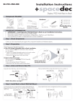
Step 1. Component Checklist
Check you have received all parts against the Component Checklist above.
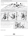
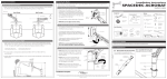
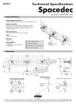
Step 2. Installing the Wall Mount Assembly (choose from one of the following options)
For mounting Spacedec to a Timber Stud Wall - Using the Wall Mount Assembly Bracket, mark
the location of the 4 holes and drill using a 4mm drill bit. Secure the bracket to the wall using the M6 Coach
Screws as shown in diagram A.
For mounting Spacedec to a Masonry Wall - Using the Wall Mount Assembly Bracket, mark
the location of the 4 holes and drill using an 8mm masonry drill bit. Secure the bracket to the wall using the M6
Coach Screws and Nylon Anchors as shown in diagram B.
Wall Mount Assembly
Bracket
Wall Mount Assembly
Bracket
4 x 4mm
Holes
Stud
4 x 8mm
Holes
Nylon Anchor
M6 Coach
Screw
Wall Material
Masonry Wall
A. Timber Stud Wall
B. Masonry Wall
M6 Coach Screw
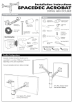
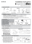
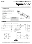
Step 3. Attach the VESA plate to your Display
There are two mounting hole configurations:
UÊÇxÊÝÊÇx
UÊ£ääÊÝÊ£ää
Choose appropriate Mounting Screws
from the Hardware supplied to suit
your Display.
Mounting Screws (x4)
VESA Plate
Top of
Display
Çx
(3”)
Çx
(3”)
£ää
(4”)
£ää
(4”)
Back of Display
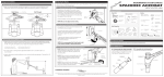
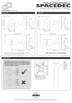
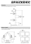
Step 4. Attach your Display to the Wall Mount Assembly
Hook the top of the VESA Plate onto
the VESA Ball Mount.
Push the bottom of the Display gently
into the VESA Ball Mount until you
hear a ‘CLICK’.
Insert the Security Screw supplied, and
tighten using the 2mm Allen Key.
TIGHTEN
Security
Screw
CLICK
2mm
Allen Key
Back of Display
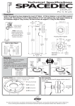
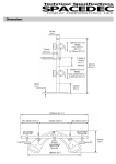
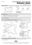
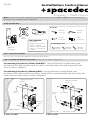
Step 5. Adjust the VESA Ball Mount
Position your Display to the desired viewing angle, using the 40°
angular movement allowed by the VESA Ball Mount.
Depending on the weight of the display, it may be necessary to make
adjustments to the VESA Ball Mount. If the display does not hold its
position, or is too resistant, adjust the Tension Plate located at the
rear of the VESA Ball Mount (see diagram right).
Tension
Plate
Loosen (-Kg)
To make any adjustments, use the Tightening Tool supplied.
Check the display, and then adjust again if necessary.
Tightening
Tool
Tighten
(+Kg)
Installation Complete
No portion of this document or any artwork contained herein should be reproduced in any way without the express written consent of Atdec Pty Ltd.
Due to continuing product development, the manufacturer reserves the right to alter specifications without notice. Published: 07.09.09 ©