Transcript
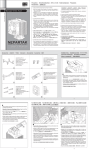
HDT-S963 Features Accessories HDT-S963 Overview ˊH.D.T. (Heat-pipe direct touch) technology. ઃዻຠ Zubehör ˊXIGMATEK HDT-S963 is an outstanding performance air cooler with heat-pipe direct touch CPU, HDT-S963 creates most efficient heat conduction and particular spoiler design to cool down maximum area of mainboard. ˊAnti-vibration rubber design. ˊParticular spoiler design. ˊ3pcs high performance U type heat-pipe. ˊLight weight. ˊHigh performance, easy installation. ˊ92mm highly efficient PWM fan. ˊDiversion-plate design. ˊ3 in 1 application: Akcesoria Accessoires ੨І Accesorios ɜ LGA 775 Push-Pin X 2 ɜ Spoiler X 1 ɜ LGA 775 Steckverbindung X 2 ɜ Spoiler X 1 ɜ LGA 775ࡊ࠶ࠪࡘࡇࡦ2 ɜ ࠬࡐࠗ1 ˊWith anti-vibration rubber for fan and 3 in 1 application retention module design, it provides users not only easier and quicker installation, but also lowest noise level. ɜ Szpilki LGA 775 X 2 ɜ Spoiler X 1 ɜ Barrette à ressort pour LGA 775 x 2 ɜ Spoiler x 1 ɜ Pasador LGA 775 X 2 ɜ Deflector aerodinámico X 1 ˊIt combines 92mm PWM fan, anti-vibration rubber, 3pcs Φ6 heat-pipe, spoiler and 3 in 1 application retention module. ɜ LGA 775 љ X 2 ɜ ጱࢲཊ X 1 1 5 For LGA775: push-pin design for faster install. HDT-S963 HDT-S1283 Overview For K8 & AM2, tool-less clip, easy to install. HDT-S1283 ˊXIGMATEK HDT-S1283 is an outstanding performance air cooler with heat-pipe direct touch CPU, HDT-S1283 creates most efficient heat conduction and particular spoiler design to cool down maximum area of mainboard. HDT-S1283 Features ˊH.D.T. (Heat-pipe direct touch) technology. ˊAnti-vibration rubber design. ˊWith anti-vibration rubber for fan and 3 in 1 application retention module design, it provides users not only easier and quicker installation, but also lowest noise level. ˊParticular spoiler design. ˊ3pcs high performance U type heat-pipe. ˊLight weight. AM2 & K8 Clip X 1 ɜ High performance Thermal Grease X 1 ɜ AM2 & K8 Clip X 1 ɜ Hochleistungs-Wärmeleitpaste X 1 ɜ AM2߅ࠃ߮K8ࠢ࠶ࡊ1 ɜ 㜞ᕈ⢻ࠨࡑ࡞ࠣࠬ1 ɜ Klamra AM2 i K8 X 1 ɜ Wysokiej wydajności pasta przewodząca X 1 ɜ Attache pour AM2 et K8 x 1 ɜ Pâte thermique haute performance x 1 ɜ Abrazadera AM2 y K8 X 1 ɜ Grasa térmica de alto rendimiento X 1 ɜ AM2 & K8 љ X 1 ɜ ጱሤჼ X 1 2 6 ˊIt combines 120mm PWM fan, anti-vibration rubber, 3pcs Φ8 heat-pipe, spoiler and 3 in 1 application retention module. ˊHigh performance, easy installation. ɜ ˊ120mm highly efficient PWM fan. ˊDiversion-plate design. ˊ3 in 1 application: For LGA775: push-pin design for faster install. For K8 & AM2, tool-less clip, easy to install. ɜ Anti-vibration rubber X 4 ɜ Fan X 1 ɜ Antivibrationsgummi X 4 ɜ Lüfter X 1 ɜ ᝄേࠧࡓ4ᧄ ɜ ࡈࠔࡦ1 ɜ Okładzina amortyzująca X 4 ɜ Wentylator X 1 ɜ Monture silencieuse en caoutchouc-métal x 4 ɜ Ventilateur x 1 ɜ Goma antivibración X 4 ɜ Ventilador X 1 ɜ ࢲै֨ዩါͯ X 4 ɜ ࢲै X 1 3 1 Installationsschritte Pasos de instalación ขࠅઃߌᚻ㗅 ɜ LGA 775 Push-pin Screw X 2 ɜ LGA 775 Steckverbindungsschraube X 2 ɜ LGA 775ࡊ࠶ࠪࡘࡇࡦࡀࠫ2ᧄ ɜ Śruba LGA 775 X 2 ɜ Vis pour LGA 775 x 2 ɜ Tornillo del pasador LGA 775 X 2 ɜ LGA 775 љᓲක X 2 http://www.xigmatek.com E-mail: [email protected] [email protected] 4 http://www.xigmatek.com Installation Step 7 Czynności instalacyjne 2 Procédure d’installation For AMD K8 & AM2 щ྅Վូᄲځ Para AMD K8 y AM2 2007 © XIGMATEK Co., Ltd. All rights reserved. All trademarks are the property of their respective owners. 3 Für AMD K8 & AM2 AMD K8߅ࠃ߮AM2ߩ႐ว AMD K8 i AM2 4 Pour AMD K8 et AM2 AMD K8 & AM2 ̝щ྅Վូᄲځ For Intel LGA 775 Für Intel LGA 775 Intel LGA 775ߩ႐ว Intel LGA 775 Pour Intel LGA 775 Intel LGA 775 ̝щ྅Վូᄲځ Para Intel LGA 775 2 Tear the package of thermal grease the bottom of heat sink base. off, apply thermal grease evenly to ɜ Reißen Sie die Packung der Wärmeleitpaste 6 auf und tragen Sie die Paste gleichmäßig auf die Unterseite des Kühlkörpers auf. ɜ 6ࠨࡑ࡞ࠣࠬߩࡄ࠶ࠤࠫࠍ㐿ኽߒߡࠢࡦࠪ࠻ࡅޔၮㇱᐩ㕙ߦࠨ ࡑ࡞ࠣࠬࠍဋ৻ߦႣࠅ߹ߔޕ ɜ Naderwij opakowanie z pastą przewodzącą część podstawy radiatora. ɜ Ouvrez le paquet de pâte thermique 6 , appliquez la pâte thermique de manière uniforme en dessous de la base du dissipateur thermique. ɜ Arranque el paquete de la grasa térmica 6 y aplique ésta uniformemente sobre la parte inferior de la base del disipador. ɜ 6 2 R A W of le lab is t th e i el us pe ou G se y N ea re Pl efo NI b ɜ 1 ɜ Before installation, peel the protect label on the bottom of heat sink base off. ɜ Ziehen Sie vor der Installation das Schutzetikett von der Unterseite des Kühlkörpers ab. ɜ ขࠅઃߌࠆ೨ߦࠢࡦࠪ࠻ࡅޔၮㇱᐩ㕙ߩ⼔ࡌ࡞ࠍߪ߇ߒ߹ߔޕ ɜ Przed instalacją, zdejmij etykietę ochronną z dolnej części podstawy radiatora. ɜ Avant l’installation, décollez l'étiquette de protection en dessous de la base du dissipateur thermique. ɜ Antes de realizar la instalación, despegue la etiqueta protectora de la parte inferior de la base del disipador. ɜ ሤጡܲొغ᜕ቯֶᐝ͞ШᇧฟĄ 6 4 , nałóż równo pastę na dolną 2 1 1 ሤჼӮ̹дሤጡତᛈ CPU ̝ొغĄ 6 1 Place 2 AM2 & K8 Clip across the fixing end of the slot at the bottom of the heat sink to engage the Retention Module. ɜ Stecken Sie den 2 AM2 & K8 Clip unter das Befestigungsende an der Unterseite des Kühlkörpers, um das Halterungsmodul einzurasten. 5 ɜ ɜ 3 6 ɜ ɜ ɜ Insert 5 spoiler into the Radiating Fin until the protruding point. Stecken Sie den 5 Spoiler in die Kühlrippen, bis dieser fest sitzt. 5 Wsuń spojler ɜ Insérez le spoiler ɜ Inserte el deflector aerodinámico que sobresale. ɜ 5 ɜ 5 dans les ailettes de refroidissement jusqu’à la partie saillante. AM2 & K8 љፖྭሤጡొغᇿؠბљҝቱळĄ ጱࢲཊबˢሤͯҌؠҜΎᕇĄ 5 LGA775 љͽ၆֎͞ёĂ̶ AăB Ѩ˭ᑅĂՏѨТॡ˭ᑅ A B ࡈࠔࡦขࠅઃߌᚻ㗅 Lüftermontage Procédure d’installation du ventilateur B ɜ Asegure el extremo móvil de la abrazadera AM2 y K8 2 en el módulo de retención y, a continuación, atorníllelo en el sentido de las agujas del reloj hasta que quede bien apretado. Para soltarlo, gire en sentido contrario a las agujas del reloj. ɜ 2 Lock 1 LGA775 Push-pin and side of the heat sink. ɜ Befestigen Sie die 1 LGA775 Steckverbindung und 4 LGA775 Steckverbindungsschrauben an der Unterseite des Kühlkörpers. ɜ 4 LGA775ࡊ࠶ࠪࡘࡇࡦ↪ࡀࠫࠍߟ߆ߞߡ ࠻ࠪࡦࠢᐩㇱߦ࿕ቯߒ߹ߔޕ Zablokuj szpilkę Bloquez la barrette à ressort 1 pour LGA775 et les vis sur la face inférieure du dissipateur thermique. ɜ Asegure el pasador LGA775 inferior del disipador. ɜ 1 LGA775 љᄃ Specyfikacje 7 2 ɜ Befestigen Sie die ɜ 3 ᝄേࠧࡓࠍ 7 3 antivibrationsgummi 7 the Fan. 7 am Lüfter. ɜ ࡈࠔࡦߦߒߞ߆ࠅ࿕ቯߒ߹ߔޕ ɜ ɜ Mocno zamocuj okładzina amortyzująca ɜ Fixez bien les monture silencieuse en caoutchouc-métal ɜ Fije de forma segura el goma antivibración del ventilador ventilador 7 . ɜ 3 ቱ֨ዩါͯĂזؠ 7 3 w wentylatorze 3 7. sur le ventilateur 3 7. ɜ en dicho ɜ ࢲै˯Ą A ɜ Insert the 7 Fan’s anti-vibration rubber into the heat sink. (It is recommended to insert the anti-vibration rubber into the third piece of the Radiating Fin.) Plug the power adapter of fan to the PWM 4pin power socket (CPU Fan) on the motherboard or plug to 12V power supply through power adapter 8 . ɜ Stecken Sie den Stromanschluss des Lüfters auf den PWN 4-pol. Stromanschluss (CPU Fan) des Motherboards oder, mithilfe des Stromanschluss-Adapters .8 , am 12V-Netzteil. 7 ᝄേࠧࡓࠍࡅ࠻ࠪࡦࠢߦᝌߒ߹ߔޕ㧔ᝄേࠧࡓߪᾲࡅߩ3⇟ ⋡ߩ⟎ߦᝌߔࠆࠃ߁߅൘ߒ߹ߔޕ㧕 ɜ Wstaw okładzina amortyzująca 7 do radiatora. (Zaleca się wstawienie okładzina amortyzująca do trzeciego żebra radiatora) ɜ ࡈࠔࡦߩ㔚Ḯࠕ࠳ࡊ࠲ࠍࡑࠩࡏ࠼ߩPWM 4ࡇࡦ㔚Ḯ࠰ࠤ࠶࠻ (CPU ࡈࠔࡦ) ߦធ⛯ߔࠆ߆ޔ㔚Ḯࠕ࠳ࡊ࠲ 8 ࠍߞߡ12V㔚Ḯߦធ⛯ߒ߹ߔޕ Podłącz adapter zasilania wentylatora do gniazda 4-pinowego gniazda zasilania PWM (Wentylator procesora) na płycie głównej lub podłącz do 12V zasilania poprzez adapter zasilania 8 . Insérez le monture silencieuse en caoutchouc-métal 7 dans le dissipateur thermique. (Il est recommandé d’insérer le monture silencieuse en caoutchoucmétal dans le troisième élément des ailettes de refroidissement). ɜ Inserte el goma antivibración del ventilador 7 en el disipador. (Es recomendable insertar el goma antivibración del ventilador en la tercera pieza del alerón radiante.) Branchez l'adaptateur d'alimentation du ventilateur sur la prise électrique PWM 4pin (Ventilateur CPU) de la carte mère ou branchez le sur l'alimentation 12V via l'adaptateur d'alimentation 8 . ɜ Enchufe el adaptador de alimentación del ventilador al zócalo de alimentación de 4 contactos PWM (ventilador del procesador) de la placa base o a la fuente de alimentación de 12 V a través del adaptador de alimentación 8 . ɜ ࢲैቢତҌ፟ ߞ˯ڕPWM 4 PIN ֻ೧ळ˯( C P U F a n ) ٕགྷ Ӥ 8 ᖼତቢତۖ 12V ֻᑕጡĄ 7 ࢲै۞ቱ֨ዩါͯӯˢሤͯ̚Ą)ޙᛉቱ֨ዩါͯ۞ӯˢҜ ཉࠎሤ᜴ͯϤ˯̈́˭ـϤ˭˯ـᇴ̝ௐ 3 ͯĄ* 12 ɜ 13 14 10 Technische Daten Spécifications ᇹ Especificaciones HDT-S1283 Specification Specyfikacje Technische Daten Spécifications Product Name HDT-S1283 CAC-S9HH3-U01 Product Number CAC-SXHH3-U01 Fan Stecken Sie die 7 antivibrationsgummi in den Kühlkörper. (Es wird empfohlen, die antivibrationsgummi in die dritte Kühlrippe des Kühlkörpers zu stecken.) ᚻ㗅AߣBߢߪኻⷺ✢ߩ 1 LGA775ࡊ࠶ࠪࡘࡇࡦࠍߒ߹ߔޕ2⚵ߩࡊ࠶ࠪ ࡘࡇࡦࠍߘࠇߙࠇหᤨߦߔߣߦࡊࡦࠢߩ࠼ࡏࡦࠗࡔ߇ࠢࡦࠪ࠻ࡅޔ ᱜߒߊ࿕ቯߐࠇ߹ߔޕขࠅᄖߔ႐วߪ⸘ᤨࠍࡦࡇࡘࠪ࠶ࡊߩࠇߙࠇߘޔ࿁ࠅ ߦ࿁ߒߡޔరߦ⟎ߦᚯߒ߹ߔޕ㧔ࡅ࠻ࠪࡦࠢࠍขࠅઃߌࠆᣇะߪᜰቯߐ ࠇߡ߹ߖࠎ߽ߢࠄߜߤޕタߢ߈߹ߔޕ㧕 HDT-S963 3 the anti-vibration rubber on ɜ en el lateral Product Number 8 3 4 Product Name 7 Securely fix Drücken Sie die 1 die LGA775 Steckverbindung diagonal in Schritt A und B. Drücken Sie beide Steckverbindungen gleichzeitig, bis der Kühlkörper fest auf dem Mainboard sitzt. Drehen Sie Sie zum Abnehmen jede Steckverbindung im Uhrzeigersinn, bis diese sich in der Ausgangsposition befinden. (Eine Ausrichtung wird nicht angegeben, der Kühlkörper kann an jeder Seite montiert werden.) pour LGA775 4 LGA775љᓲකĂᗆܢдሤጡొغĄ HDT-S963 Specification Heat-pipe 1 ɜ LGA775 w dolnej części radiatora. y los tornillos del mismo 1 Press 1 the LGA775 Push-pin diagonally in Step A and B. Press the two units of Push-pin simultaneously each time until the heat sink can be securely clamped on the main board. To dismantle, turn each Push-pin in a clockwise direction to return to the original position. (Orientation is not provided for installing the heat sink, which can be mounted on each side.) 9 Heat Sink ɜ 4 4 ɜ LGA775ࡊ࠶ࠪࡘࡇࡦࠍࡅ ɜ 1 LGA775 i śruby 1 ɜ 8 ࢲैщ྅Վូᄲځ 7 LGA775 Push-pin screws onto the bottom 4 AM2 & K8 љ߿̝જბљҝቱळĂึॡ੫ԳღĂ̝ͅעٵĄ 3 ɜ 11 Fixez l’extrémité mobile de l’attache 2 pour AM2 et K8 dans le module de maintien puis vissez-la fermement dans le sens des aiguilles d’une montre. Pour libérer, tourner dans le sens inverse des aiguilles d’une montre. Czynności instalacji wentylatora Pasos para instalar el ventilador ɜ 1 ɜ 7 Presione el pasador LGA775 1 en diagonal en los pasos A y B. Presione las dos unidades de los pasadores simultáneamente hasta que el disipador se pueda sujetar perfectamente en la placa base con la abrazadera. Para el desmontaje, gire cada uno de los pasadores en sentido contrario a las agujas del reloj para recuperar la posición original. (La orientación no se proporciona para instalar el disipador, que se puede montar en cada lado.) љĂሤጡΞͽቁ၁гљЪд፟˯ڕćעٵॡΪᅮึॡ੫͞Ш ᖼՏ࣎љࢦາؠ۞ֽࣧזҜĄ)щ྅ሤጡॡ͞ШّĂα͞ӮΞ щ྅* Zamocuj ruchomy koniec 2 klamry AM2 i K8 do modułu podtrzymującego, a następnie dokręć go mocno w kierunku wskazówek zegara. W celu zwolnienia, odkręć w kierunku przeciwnym do wskazówek zegara. en el alerón radiante hasta el punto 5 Appuyez en diagonale sur la barrette à ressort 1 pour LGA775 dans les étapes A et B. Appuyez simultanément sur les deux barrettes à ressort jusqu’à ce que le dissipateur thermique soit bien maintenu sur la carte mère. Pour démonter, tournez chaque barrette à ressort dans le sens des aiguilles d’une montre pour revenir à la position d’origine. (L’orientation n’est pas donnée pour l’installation du dissipateur thermique, lequel peut être monté de chaque côté). 1 2 AM2߅ࠃ߮K8ߩࠢ࠶ࡊߩ⌕⣕┵ࠍ࠹ࡦ࡚ࠪࡦࡕࠫࡘ࡞ߦធ⛯ߒࡀޔ ࠫࠍᤨ⸘࿁ࠅߦ࿁ߒߡ࿕ቯߒ߹ߔޕขࠅᄖߔ႐วߪޔᤨ⸘࿁ࠅߦ࿁ߒ߹ߔޕ 2 ɜ 2 ɜ Mettez en place l’attache 2 pour AM2 et K8 au niveau de l’extrémité de fixation de l’encoche en bas du dissipateur thermique afin de mettre en place le module de maintien. 6 Naciśnij szpilki 1 LGA775 po przekątnej w czynności A i B. Naciśnij równocześnie dwie szpilki, aż do zaskoczenia radiatora na miejsce w płycie głównej. W celu demontażu, obróć każdą szpilkę w kierunku wskazówek zegara, aby przywrócić oryginalną pozycję. (Orientacja nie ma znaczenia podczas instalacji radiatora, można go instalować na dowolnej stronie) Befestigen Sie das bewegliche Ende des 2 the AM2 & K8 Clips am Halterungsmodul und schrauben Sie es im Uhrzeigersinn fest. Drehen Sie zum Lösen gegen den Uhrzeigersinn. Wstaw klamrę AM2 i K8 naprzeciw gniazda mocującego w dolnej części radiatora w celu zamocowania modułu podtrzymującego. ɜ między żebra radiatora, aż do oporu. Fan Installation Steps ɜ ɜ 2 Coloque la abrazadera AM2 y K8 2 a través del extremo de fijación de la ranura que se encuentra en la parte inferior del disipador para engranar el módulo de retención. ࠬࡐࠗࠍ⓭ὐ߹ߢᾲࡅߩ㑆ߦᝌߒ߹ߔޕ ɜ 5 ɜ Secure the moveable end of 2 the AM2 & K8 Clip onto the Retention Module and then screw it tight in a clockwise direction. To release, turn in the counter-clockwise direction. 2 AM2߅ࠃ߮K8ߩࠢ࠶ࡊࠍߺ߆ߣ࡞ࡘࠫࡕࡦ࡚ࠪࡦ࠹ޔว߁ࠃ߁ ߦࠢࡦࠪ࠻ࡅޔᐩㇱߩࠬࡠ࠶࠻ߩ࿕ቯ┵ߦ㈩⟎ߒ߹ߔޕ ɜ 1 ɜ ɜ ɜ ɜ 2 ɜ Base Material H.D.T. (Heat-pipe Direct Touch) Fin Material Aluminum Alloy Heat-pipe SPEC ɓ6mm Heat-pipe No. 3 Dimension Voltage Rating Heat Sink Especificaciones Base Material H.D.T. (Heat-pipe Direct Touch) Fin Material Aluminum Alloy Heat-pipe SPEC ɓ8mm Heat-pipe No. 3 92(W) x 92(H) x 25(D) mm Dimension 120(W) x 120(H) x 25(D) mm 12 V Voltage Rating 12 V Speed 1200~2800 R.P.M. Speed 1000~2200 R.P.M. Bearing Type Rifle Bearing Bearing Type Rifle Bearing Air Flow 39~54.6 CFM Air Flow 72.1~99.6 CFM Air Pressure 1.7~3.3 mmH2O Air Pressure 2.6~4.8 mmH2O Life Expectance 50,000 hrs Life Expectance 50,000 hrs Noise Level 23~35 dBA Noise Level 20~32 dBA Connector 4 pin with PWM Connector 4 pin with PWM Heat-pipe Fan Dimension 92(W) x 50(H) x 134(D) mm Dimension 120(W) x 50(H) x 159(D) mm Thermal Resistance 0.18 ƨ / W Thermal Resistance 0.16 ƨ / W Weight 410g (w / fan) Weight 600g (w / fan) Application ᇹ All Intel® Socket 775 CPU All Intel® Socket 775 CPU Core™2 Extreme / Quad / Duo Core™2 Extreme / Quad / Duo Pentium® Extreme Edition / D Celeron® D Application Pentium® Extreme Edition / D Celeron® D All AMD Socket AM2 / 754 / 939 / 940 CPU All AMD Socket AM2 / 754 / 939 / 940 CPU Athlon™ 64 / FX / X2 / Opteron™ / Sempron™ Athlon™ 64 / FX / X2 / Opteron™ / Sempron™ 15 16