1
NETWORK VIDEO RECORDER
VK-64/VK-16
Administrator’s Manual
Ver. 2.2
Introduction
Thank you for purchasing Network Video Recorder VK-64 v2.2 (hereafter referred to as VK-64). VK-64 is
a network video recording and monitoring system and consists of the Storage Server and Viewer.
Please read this manual prior to operation. This manual also explains how to use the Network Video
Recorder VK-16 v2.2 (hereafter referred to as VK-16), VK-Lite v2.2 (hereafter referred to as VK-Lite),
and Viewer-Only use. See P. 1-6 for the difference between the VK-64 and VK-16. See P. 1-30 for the
difference between VK-64/VK-16 and VK-Lite. See P. 5-8 for the functions not available in the Viewer
Only mode.
*
VK-16 and VK-Lite have the same functionality as VK-64 outlined in this manual, unless explicitly indicated
otherwise.
Request to Customers
1. Canon owns the copyright of this manual. The unauthorized transfer of all or any part of the contents
of this Manual is forbidden.
2. The contents of this manual are subject to change without any notice.
3. This document has been prepared with the utmost attention to accuracy. However, if you have any
comment, please contact the Customer Service Center indicated on the back cover.
4. Irrespective of items (2) and (3) above, Canon cannot bear responsibility for any effects resulting
from operation.
5. When procedures that involve using the control panel are described in this manual, the operations
are described as shown in Windows Vista Basic.
Disclaimer
Malfunction and failure of the software, or other factors may cause problems, such as recording failure,
recorded data corruption or loss. Canon shall have no liability whatsoever for any loss or damages
incurred by the user as a result of such problems.
Support Information
For various types of information relating to support, including updated product software (patch
installer), User's Manual, operating environment, etc., please see the Canon Web site.
Copyright Information
Videos, images or sounds recorded with your camera may not be utilized or published, without consent
of copyright holders, if any, except in such a way as permitted for personal use under the relevant
copyright law.
Trademark Notice
z Canon and the Canon logo are registered trademarks of Canon Inc.
z Microsoft, Windows, Windows Server, Windows Vista and Internet Explorer are registered trademarks
or trademarks of Microsoft Corporation in the United States and other countries.
z Windows is legally recognized as Microsoft Windows Operating System.
z QuickTime is a trademark of Apple Inc.
z Apache is a trademark of the Apache Software Foundation.
z Pentium is a trademark of Intel Corporation.
z All other company or product names used in this manual are trademarks or registered trademarks of
their respective holders.
ii
Introduction
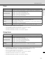
Icons Used in this Manual
The following icons are used in this guide to indicate descriptions that you should read in particular.
Icon
Explanation
Note
Important information that must be observed or actions that are prohibited during an
operation. These notes must be read to prevent possible faults or errors during
operation.
Tip
Supplementary information or a reference to an operation. Users are recommended to
read these memos.
Storage Server includes software developed by the Apache Software Foundation (www.apache.org).
Apache software is protected by the copyright law (Copyright© 2000-2003 Apache Software
Foundation). For the license terms associated with this software, please see the file APACHE_LICENSE
in the LICENSE folder, in the installation directory.
MPEG-4
NOTICE ABOUT THE MPEG-4 VISUAL STANDARD: THIS PRODUCT IS LICENSED UNDER THE
MPEG-4 VISUAL PATENT PORTFOLIO LICENSE FOR THE PERSONAL AND NON-COMMERCIAL USE
OF A CONSUMER TO (i) ENCODING VIDEO IN COMPLIANCE WITH THE MPEG-4 VISUAL STANDARD
("MPEG-4 VIDEO") AND/OR (ii) DECODING MPEG-4 VIDEO THAT WAS ENCODED BY A CONSUMER
ENGAGED IN A PERSONAL AND NON-COMMERCIAL ACTIVITY. NO LICENSE IS GRANTED OR
SHALL BE IMPLIED FOR ANY OTHER USE. ADDITIONAL INFORMATION INCLUDING THAT RELATING
TO PROMOTIONAL, INTERNAL AND COMMERCIAL USES AND ADDITIONAL LICENSING MAY BE
OBTAINED FROM MPEG LA, LLC. SEE HTTP://WWW.MPEGLA.COM.
This product is licensed under AT&T patents for the MPEG-4 standard and may be used for encoding
MPEG-4 compliant video and/or decoding MPEG-4 compliant video that was encoded only (1) for a
personal and non-commercial purpose or (2) by a video provider licensed under the AT&T patents to
provide MPEG-4 compliant video. No license is granted or implied for any other use for MPEG-4
standard.
Open Source Software
This product contains open source software modules. Each module's license conditions are also
available in the OpenSourceSoftware folder in the LICENSE folder on the accompanying Setup CDROM.
Software
License
License Agreement
Apache
Apache Software License, Version 1.1
Apache
FastCGI
Open Market License
FastCGI
Expat
MIT License
Expat
iii
Purpose of This Manual
This manual is written for the System Administrator installing and operating the VK-64/VK-16 system.
It explains the functions of VK-64/VK-16 and introduces more appropriate system deployment methods.
Use this manual as a reference when making a backup of data or troubleshooting a problem.
iv
Contents
Introduction ................................................................................................................................ ii
Purpose of This Manual ............................................................................................................ iv
About Manuals ..........................................................................................................................xii
Important: Before Starting Operations .....................................................................................xiii
Chapter 1
System Overview
Chapter Overview ...................................................................................................................1-2
Preparation Flow .....................................................................................................................1-4
System Operation Overview ...................................................................................................1-6
VK-64/VK-16 Overview .......................................................................................................................... 1-6
Communication Mechanism of VK-64/VK-16 ..........................................................................1-8
Typical System Configuration ............................................................................................................... 1-8
Operating Environment .........................................................................................................1-10
Supported Camera Servers ................................................................................................................ 1-10
System Environment ............................................................................................................................ 1-10
Viewer .................................................................................................................................................. 1-11
Storage Server .................................................................................................................................... 1-11
Notes on Operating Environment ..........................................................................................1-12
Notes on Use with Windows XP .......................................................................................................... 1-12
Notes on Use with Windows XP/Vista ................................................................................................. 1-12
Windows Server 2003/Windows Server 2008 ..................................................................................... 1-13
Windows Server 2008 ......................................................................................................................... 1-15
Windows Vista/Windows Server 2008 ................................................................................................. 1-16
System Design Concept .......................................................................................................1-17
System Configuration Example ........................................................................................................... 1-17
When using multiple Storage Servers ................................................................................................. 1-19
When using Viewer alone .................................................................................................................... 1-19
Server Sizing Concept ........................................................................................................................ 1-20
Approximate Video Data Volume per Second .................................................................................... 1-20
Required Hard Disk Capacity ............................................................................................................. 1-21
Sensor Event Recording and Motion Detection Recording Concept ................................................. 1-24
Storage Server Performance ............................................................................................................... 1-25
Notes on Viewer Sizing ....................................................................................................................... 1-26
Network Bandwidth Concept .............................................................................................................. 1-27
VK-Lite ..................................................................................................................................1-28
Specification Comparison of VK-64/VK-16 and VK-Lite ........................................................1-30
Chapter 2
Installation
Chapter Overview ...................................................................................................................2-2
Installation Procedures ...........................................................................................................2-3
Start up the Installer .............................................................................................................................. 2-3
Upgrade from Version 1.0, 1.1, 1.2, 1.3, 1.4, 2.0 and 2.1 ..................................................................... 2-6
Preparation and Precaution .................................................................................................................. 2-7
v
Contents
Chapter 3
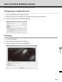
Storage Server Configuration Reference
Chapter Overview ...................................................................................................................3-2
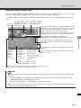
[Storage Server Configuration] Dialog ....................................................................................3-3
How to Start-Up ..................................................................................................................................... 3-3
Screen Configuration ............................................................................................................................ 3-4
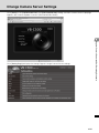
Set the [Settings] Tab .............................................................................................................3-8
How to Display the [Settings] Tab ......................................................................................................... 3-8
How to set the [Settings] Tab ................................................................................................................ 3-9
Message .............................................................................................................................................. 3-15
[Logon As Service] Privilege ............................................................................................................... 3-15
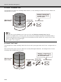
Important: Disk Space Management .....................................................................................3-17
Disk Space Management Level .......................................................................................................... 3-17
Handling at Each Level ....................................................................................................................... 3-17
[Low disk space warning level] Calculation Method ........................................................................... 3-19
Threshold Level Calculation Method ................................................................................................... 3-19
Limit Level Calculation Method ........................................................................................................... 3-20
Calculation Example for Each Level ................................................................................................... 3-20
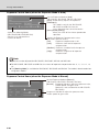
Set [Events] Tab
.................................................................................................................3-21
How to Display the [Events] Tab ......................................................................................................... 3-21
How to Set the Events Tab .................................................................................................................. 3-22
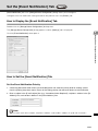
Set the [Event Notification] Tab
..........................................................................................3-23
How to Display the [Event Notification] Tab ........................................................................................ 3-23
How to Set the [Event Notification] Tab .............................................................................................. 3-23
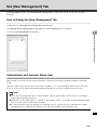
Set [User Management] Tab .................................................................................................3-25
How to Display the [User Management] Tab ...................................................................................... 3-25
Administrator and Operator Status User ............................................................................................. 3-25
How to Set the [User Management] Tab ............................................................................................. 3-26
Change User to Administrator ............................................................................................................. 3-26
Delete a User ...................................................................................................................................... 3-27
Request User Authentication at Tool Startup ...................................................................................... 3-27
Chapter 4
Register Camera Server and Set Recording Schedule
Chapter Overview ...................................................................................................................4-2
Launch VK Viewer and Display the [Configuration and Preferences] Screen .........................4-3
How to Launch VK-64/VK-16 ................................................................................................................. 4-3
How to Start VK-Lite .............................................................................................................................. 4-4
Launch by Connecting to the Localhost ............................................................................................... 4-4
Launch Storage Server by Specifying the IP address .......................................................................... 4-5
Access to the Configuration and Preferences screen .......................................................................... 4-7
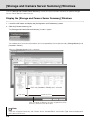
[Storage and Camera Server Summary] Windows .................................................................4-8
Display the [Storage and Camera Server Summary] Windows ............................................................ 4-8
[Storage Server] and [Locations / Zones] options ................................................................................ 4-9
Other Functions in Both Tabs ................................................................................................................ 4-9
vi
Contents
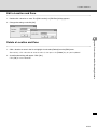
Location and Zone ................................................................................................................4-10
Add a Location and Zone ................................................................................................................... 4-12
Edit a Location and Zone .................................................................................................................... 4-13
Delete a Location and Zone ................................................................................................................ 4-13
Add Storage Server
............................................................................................................4-14
Display [Storage and Camera Server Summary] Windows ................................................................ 4-14
Add Storage Server ............................................................................................................................. 4-14
Edit Storage Server ............................................................................................................................. 4-15
Delete Storage Server ......................................................................................................................... 4-16
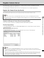
Register Camera Server .......................................................................................................4-17
Register the Camera Server (by Search) ............................................................................................ 4-17
Edit Camera Server ............................................................................................................................. 4-24
Delete Camera Server ......................................................................................................................... 4-26
Overview of Recording Schedule Setting .............................................................................4-27
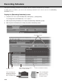
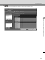
Recording Schedule ..............................................................................................................4-28
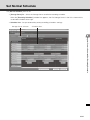
Set Normal Schedule ............................................................................................................4-31
Create Normal Schedule ..................................................................................................................... 4-32
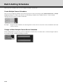
Change Camera Server Settings ..........................................................................................4-41
Batch-Setting Schedules .......................................................................................................4-44
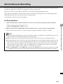
Set Continuous Recording ....................................................................................................4-45
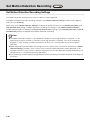
Set Motion Detection Recording
.........................................................................................4-46
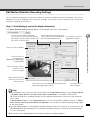
Set Motion Detection Recording Settings ........................................................................................... 4-46
Edit Motion Detection Recording Settings .......................................................................................... 4-47
Set Sensor Event Recording ...............................................................................................4-53
Set Sensor Event Recording Settings ................................................................................................. 4-53
Edit Sensor Event Recording Settings ................................................................................................ 4-54
Set Preset Tour .....................................................................................................................4-58
Set Preset Tour .................................................................................................................................... 4-58
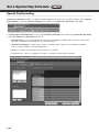
Set a Special Day Schedule
...............................................................................................4-62
Special Day Recording ....................................................................................................................... 4-62
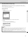
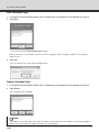
Add, Edit and Delete a Schedule Type ............................................................................................... 4-63
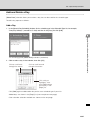
Add and Delete a Day ......................................................................................................................... 4-65
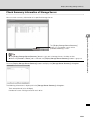
Display Recording Setting Summary ....................................................................................4-68
Check Summary Information of a Recording Schedule ...................................................................... 4-68
Check Summary Information of Storage Server .................................................................................. 4-69
vii
Contents
Chapter 5
Viewer Reference
Chapter Overview ...................................................................................................................5-2
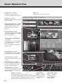
Viewer Operation Flow ............................................................................................................5-4
Start the Viewer ......................................................................................................................5-6
How to Launch ................................................................................................................................ 5-6
Launch by Connecting to the localhost .......................................................................................... 5-7
Launch Storage Server by Specifying the IP address ................................................................... 5-7
Launch without Storage Server (Viewer Only Mode) ...................................................................... 5-8
Functions not Available in Viewer Only Mode ................................................................................ 5-9
Viewer Start-up Window ............................................................................................................... 5-10
Viewer Start-up Option ................................................................................................................. 5-11
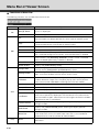
Menu Bar of Viewer Screen ..................................................................................................5-12
Functions of Menu Bar .................................................................................................................. 5-12
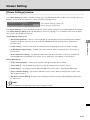
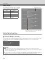
Viewer Setting .......................................................................................................................5-13
[Viewer Settings] window .................................................................................................................... 5-13
Set the Tab for Administrator .............................................................................................................. 5-14
Set whether to select the Master Storage Server when the Viewer starts up ............................... 5-14
Set layout of the Viewing Screen .................................................................................................. 5-14
Set Event Popups ......................................................................................................................... 5-14
Set Event Notifications .................................................................................................................. 5-15
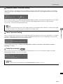
Set the Tab for Guest User .................................................................................................................. 5-16
Frame Rate Setting for live video .................................................................................................. 5-16
Automatic Audio Termination Setting ........................................................................................... 5-17
Focus Operation Setting ............................................................................................................... 5-17
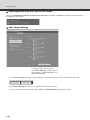
Proxy Server Setting ................................................................................................................... 5-17
Superimpose the Date and Time on Still Frames ......................................................................... 5-18
Save Viewer Settings .................................................................................................................... 5-18
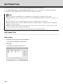
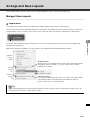
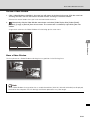
Arrange and Save Layouts ...................................................................................................5-19
Manage Video Layouts ....................................................................................................................... 5-19
Layout menu ................................................................................................................................. 5-19
Organize Layouts and Layout Sequences ................................................................................... 5-20
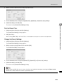
Save a Layout or Layout Sequence .............................................................................................. 5-22
Arrange Layout Sequences ........................................................................................................ 5-23
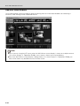
Layout Grids ........................................................................................................................................ 5-24
Alignment Grid .............................................................................................................................. 5-25
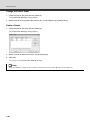
Custom Grid ................................................................................................................................. 5-28
Hide and Show Task Areas ................................................................................................................. 5-29
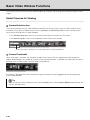
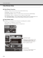
Basic Video Window Functions .............................................................................................5-30
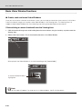
Select Cameras for Viewing ................................................................................................................ 5-30
Camera Selection Area ................................................................................................................. 5-30
Camera Thumbnails ..................................................................................................................... 5-30
Locations and the Zones .............................................................................................................. 5-31
Basic Video Window Functions ........................................................................................................... 5-32
Create, scale and move Video Windows ...................................................................................... 5-32
viii
Contents
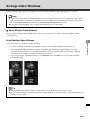
Arrange Video Windows .......................................................................................................5-35
Select Multiple Video Windows .................................................................................................... 5-35
Video Window Status .......................................................................................................................... 5-36
Video Window Properties ............................................................................................................. 5-36
Video Window states .................................................................................................................... 5-36
Pan, Tilt, Zoom Control ........................................................................................................................ 5-38
Other Video Window Functions ........................................................................................................... 5-43
Change the Video Window size .................................................................................................... 5-43
Change the Received Video size (VB-C500VD, VB-C500D, VB-C60,
VB-C50i/VB-C50iR, VB-C50FSi, VB-C50Fi only) ............ 5-44
Enable Exposure Compensation .................................................................................................. 5-45
Other Menu Options ..................................................................................................................... 5-46
Viewer Shade Control ................................................................................................................... 5-47
Audio Panel .................................................................................................................................. 5-47
Use Timeline and View Events .............................................................................................5-48
Timeline Overview ........................................................................................................................ 5-48
Monitor Live Video in relation to the Timeline ............................................................................... 5-49
Use the Timeline to play and extract video .................................................................................. 5-50
One-minute manual recording (Record Now) .............................................................................. 5-52
Shoot a Snapshot ......................................................................................................................... 5-53
Daylight Savings Indicator ............................................................................................................ 5-54
Extract video to save to a file ........................................................................................................ 5-54
View and Search Events ..................................................................................................................... 5-56
[Live Events Log] list .................................................................................................................... 5-56
Display the [Live Events Log] list ................................................................................................. 5-56
Overview of Alert Parameters ....................................................................................................... 5-57
Search Events ............................................................................................................................... 5-58
Select Criteria for Searching ......................................................................................................... 5-59
View retrieved recorded video ..................................................................................................... 5-60
Popup Video upon Event occurring .................................................................................................... 5-61
Chapter 6
Operation and Management
Chapter Overview ...................................................................................................................6-2
Health Check for Storage Server ............................................................................................6-3
VK Events (Timeline for VK Viewer) ....................................................................................................... 6-3
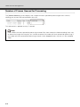
Number of Frames Queued for Processing .......................................................................................... 6-4
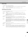
Operation Guideline for Recording and Viewing .....................................................................6-5
Live-View Frame Rate Adjustment ........................................................................................................ 6-5
Recording Frame Rate Adjustment ....................................................................................................... 6-5
Operational Guideline for Sensor Event Recording ................................................................6-6
Proper Operation of Sensor Event Recording
(Optimization of Sensor Arrangement and Sensitivity) ..... 6-6
Optimization of Motion Detection Recording (Index) ...............................................................6-7
ix
Contents
Chapter 7
Backup Scheme
Chapter Overview ...................................................................................................................7-2
Purpose ...................................................................................................................................7-3
Preparation .............................................................................................................................7-4
Backup Device ...................................................................................................................................... 7-4
Backup Tool .......................................................................................................................................... 7-4
Restore Server for Archiving ................................................................................................................. 7-4
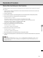
Files to Make a Backup ...........................................................................................................7-5
Storage Location of Video Data, Audio Data, and Event Data ............................................................. 7-5
Backup for Data Protection .....................................................................................................7-8
About Backup ....................................................................................................................................... 7-8
Backup for Archiving (Long-Term Storage of Data) ................................................................7-9
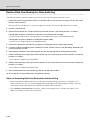
Backup Procedure for Video Data and Event Data ...............................................................7-10
Restoration Procedure ..........................................................................................................7-11
Restore Data from Backup for Data Protection ................................................................................... 7-11
Restore Data from Backup for Data Archiving .................................................................................... 7-12
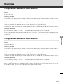
Examples ..............................................................................................................................7-13
Configuration 1: Backup for Data Protection 1 ................................................................................... 7-13
Configuration 2: Backup for Data Protection 2 ................................................................................... 7-13
Configuration 3: Backup for Data Archiving ....................................................................................... 7-14
Configuration 4: Backup from Multiple Storage Servers (Backup for Data Protection) ...................... 7-14
Chapter 8
System Maintenance
Chapter Overview ...................................................................................................................8-2
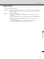
Upgrade VK-64/VK-16 ............................................................................................................8-3
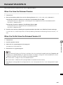
Reinstall VK-64/VK-16 ............................................................................................................8-5
When You Have the Released Version ................................................................................................. 8-5
When You Do Not Have the Released Version 2.2 ............................................................................... 8-5
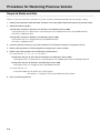
Procedure for Restoring Previous Version ..............................................................................8-6
Required Media and Data ..................................................................................................................... 8-6
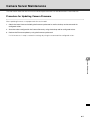
Camera Server Maintenance ..................................................................................................8-7
Procedure for Updating Camera Firmware ........................................................................................... 8-7
x
Contents
Chapter 9
Troubleshooting
Chapter Overview ...................................................................................................................9-2
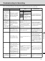
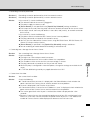
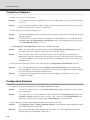
Troubleshooting for Recording ................................................................................................9-3
VK Troubleshooting ................................................................................................................9-4
Viewing Screen and Video Windows .................................................................................................... 9-4
Timeline ................................................................................................................................................. 9-6
Extract Video ......................................................................................................................................... 9-7
Scheduling and Recording ................................................................................................................... 9-7
Connection Problems ............................................................................................................................ 9-8
Configuration Problems ......................................................................................................................... 9-8
Upgrade Problems ................................................................................................................................ 9-9
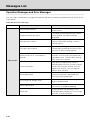
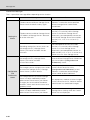
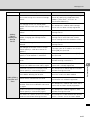
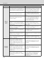
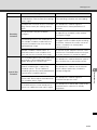
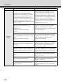
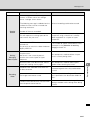
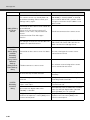
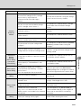
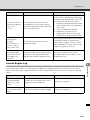
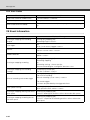
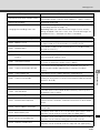
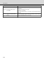
Messages List .......................................................................................................................9-10
Operation Messages and Error Messages ......................................................................................... 9-10
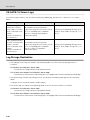
VK-64/VK-16 Recording Engine Logs ................................................................................................. 9-26
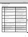
Access Engine Log ............................................................................................................................. 9-29
VK-64/VK-16 Viewer Logs ................................................................................................................... 9-30
Log Storage Destination ...................................................................................................................... 9-30
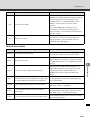
Error Codes in Log File ....................................................................................................................... 9-31
VK Event Information ........................................................................................................................... 9-34
Chapter 10 Appendix
Camera Server Control .........................................................................................................10-2
Hard Disk ..............................................................................................................................10-3
Lifetime of Hard Disk ........................................................................................................................... 10-3
RAID Reconfiguration .......................................................................................................................... 10-3
How To Check Software Version ..........................................................................................10-5
Storage Server Configuration tool ....................................................................................................... 10-5
VK Viewer ............................................................................................................................................ 10-5
Functional Limitations on MPEG-4 .......................................................................................10-6
Index .....................................................................................................................................10-7
xi
About Manuals
VK-64/VK-16 comes with three manuals including this document.
z Setup Guide
A manual that introduces this software.
Be sure to read this manual when using the software for the first time.
z Viewer Operation Guide
A simplified manual for the VK Viewer.
Be sure to read the Administrator’s Manual for details.
z Administrator’s Manual (this manual - pdf file)
This manual is intended for the System Administrator to install and operating this software.
Be sure to read this manual to ensure proper system operation.
xii
Important: Before Starting Operations
It is recommended that you perform tests under actual conditions before starting operations.
z This recording software may not operate as your settings in recording or displaying live video, depending on
the capabilities of your PC and the network environment.
z When load on your computer CPU and hard disk is high, the specified frame rate may not be available, or
the video recording may be interrupted or the Viewer operation may take longer. Also, when available disk
space is low, the disk load may increase and the video recording may be interrupted.
z The performance of storage servers and viewers may be negatively affected on the PC, where anti-virus
software or firewall is running.
z If you use a proxy server, recording frame rate may not be achieved as specified or live video monitoring
may be interrupted. Also, communication between the Storage Server and Viewer may occasionally be
disconnected. ( P. 3-9, P. 4-5)
z If you are operating using IPSec, the recording and display performance may be degraded.
z See "Notes on Operating Environment" ( P. 1-12 ~ P. 1-16) for information on OS you use.
z When recording to a NAS server, it is recommended to separate the communication networks for the camera
and NAS.
z Use recommended NAS servers with Windows Storage Server 2003 or Windows Storage Server 2003 R2.
z Although the audio function of the VB-C500VD, VB-C500D, VB-C60, VB-C300, VB-C50i, VB-C50iR, and
VB-C50FSi can also be used, take note of the following warnings.
• The VK Viewer supports audio transmission and reception.
• Audio data can be recorded. However, audio data cannot be recorded individually, and must be
recorded together with video data.
• Only when playing video, the recorded video (JPEG) is synchronized with the recorded audio.
However, the audio and images may not synchronize depending on the environment ( P. 4-35).
• The audio stream may be interrupted due to the performance of your PC and the network
environment.
• The audio function is not available via a proxy server.
• Audio may be interrupted on the PC where anti-virus software is running.
z The software may not be able to record video, if you use it under the condition where the IP address of
storage servers or camera servers are occasionally changed. So, please be sure to use fixed IP addresses.
xiii
Important: Before Starting Operations
xiv
System Overview
Chapter Overview
This chapter provides preliminary information you should know before using the VK-64/VK-16 and explains the
operating environment and basic concept you need to understand to design your system.
Preparation Flow
Explains the flow from setting up the VK-64/VK-16 to starting the operation.
System Operation Overview
Explains the system operating environment such as the number of Camera Servers available for the Storage
Server, product types, and the number of licenses for each product.
Communication Mechanism of VK-64/VK-16
Explains the communication mechanism of the VK-64/VK-16 with, using a typical system configuration.
Operating Environment
Explains operating environment of the VK-64/VK-16 and points of notice regarding the OS environment.
Notes on Operating Environment
Explains about each version of Windows OS.
System Design Concept
Explains the concept and points of notice when you design the system.
VK-Lite
Explains about functional limitations and the specification comparison between VK-Lite and VK-64/VK-16.
1-2
Chapter Overview
1
System Overview
1-3
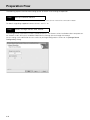
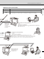
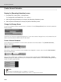
Preparation Flow
The following explains the flow from setting up the VK-64/VK-16 to starting the operation.
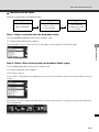
Step1
Set up Camera Servers
The first step is to set up your Camera Servers. See your Camera Server manuals for connection in detail.
For details regarding supported camera servers, see P. 1-10.
Step2
Install Storage Server and Viewer
The Storage Server and Viewer can be installed on one PC. The Viewer can be installed on other computers on
the network, and it will access recorded video from the Storage Server through the network.
Server setting, event notification to users and user privilege configuration can be set via [Storage Server
Configuration] dialog.
1-4
Preparation Flow
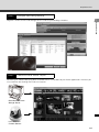
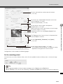
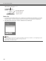
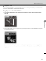
Step3
Configure Recording Settings
1
Register Camera Servers and Storage Servers and set up recording schedules.
System Overview
Step4
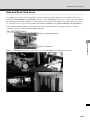
Create and save Viewer Layout
Monitoring live video and playing back recorded events can be done by the Viewer application. And also you
can customize the Viewing Area and save Layouts.
Recorded video from
Storage Server
Live video from
Camera Servers
1-5
System Operation Overview
VK-64/VK-16 Overview
Network Video Recorder
Network Video Recorder is software for viewing video, recording video and audio, and playing back video from
multiple network cameras (hereafter referred to as Camera Servers). This supports viewing and recording
JPEG and MPEG-4 video, bidirectional audio communication, and recording audio.
Composition of Network Video Recorder
Network Video Recorder consists of two software component: a Storage Server and a Viewer.
The Storage Server can record video from multiple Camera Servers, and can also record event information
from motion detection and external device inputs. The Viewers can show the live video from multiple Camera
Servers, and playback video recordings saved on a Storage Server.
Product Type
Number of Camera Servers Used
Product Name
Storage Server
Viewer
Network Video Recorder VK-64 v2.2
1 license
1 license
Network Video Recorder VK-16 v2.2
1 license
1 license
Network Video Recorder VK-64 v2.2 Viewer
-
1 license
Network Video Recorder VK-16 v2.2 5 Viewers
-
5 licenses
Network Video Recorder VK-64
Network Video Recorder VK-64 (hereafter referred to as VK-64) can register and use up to a maximum of 64
Camera Servers.
1-6
System Operation Overview
Network Video Recorder VK-16
Network Video Recorder VK-16 (hereafter referred to as VK-16) has the same basic functionality as VK-64, but
is only able to register up to 16 Camera Servers.
A comparison between VK-64 and VK-16 is as follows.
*
Storage Server
VK-64
Maximum number of registered Camera Servers: 64 units
VK-16
Maximum number of registered Camera Servers: 16 units
All other functions are the same as the VK-64
System Overview
Type
1
Viewer
Same
The Viewer for VK-64 and VK-16 is the same.
VK-64 Viewer (Using the Viewer Only)
If you want to use additional Viewers, purchase the required number of viewer license. If you do not need to
record video, the Viewer can be used in a standalone configuration.
You can perform live viewing and camera control of up to 64 units (cannot use functions such as recording and
playback, display event information from motion detection and external device inputs, or still frames).
Upgrading from a Previous Version
To upgrade from an older version (v1.1, v1.2, v1.3, v1.4, v2.0 or v2.1) to v2.2, download the free patch install
from our website. License keys from older versions can also be valid in v2.2.
Network Video Recorder VK-Lite
The Network Video Recorder VK-Lite which is bundled with the VB-C500VD, VB-C500D and VB-C60 is a
simplified version of VK-64/VK-16. VK-Lite can display video, record video and audio, and playback for up to 4
Camera Servers.
1-7
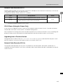
Communication Mechanism of VK-64/VK-16
The following explains the communication mechanism of the VK-64/VK-16, with using atypical system
configuration.
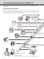
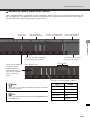
Typical System Configuration
VK-64/VK-16 provides video viewing and recording from Camera Servers via an IP network such as a LAN.
Since VK-64/VK-16 makes use of IP networks, cameras can be installed easily. And also addition of new
camera or change of camera location can be done flexibly.
Live
VC-C50i
VC-C50iR
VB150
VB-C60
ba
Playback
Live
VB-C300
Monitor
Pl
Li
ve
ay
ba
ck
VB-C50i
VB-C50FSi
VB-C50iR
Monitor
View live and recorded video
Viewer
Operator Capabilities:
Viewing Live Video Viewing Events Viewing recorded video
1-8
ay
Li
VB-C500D
Pl
ve
ck
VB-C500VD
Communication Mechanism of VK-64/VK-16
Application Types and Functions
Application
Viewer
System Overview
Storage Server
1
Function
Save logs information of such as video, audio, and events.
User can view recorded information, monitor live-video and check and search events
from recording server. Administrator can configure the storage server setting.
Record
Playback
Receive and
record video
Play back
recorded video
by Viewer.
Record video to the Storage Server #1
Server
Administrator Capabilities:
Configuring Storage Server Configuring Event Notification
Configuring Users
Display live and recorded video
Viewer
Administrator Capabilities:
Configure recording settings Configure event alerts
Viewing Live Video Viewing Events Viewing recorded video
Configuring Camera Servers Configuring Storage Server
Playback
Record
Monitor
Record video to the
Storage Server #2
Storage Server
1-9
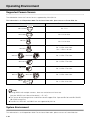
Operating Environment
Supported Camera Servers
The table below shows the Camera Servers supported by VK-64/VK-16.
This information is as of September 2009. For the latest information, please access to Canon Web site.
Camera Server
Firmware Versions
VB-C500VD
Ver. 1.1 0
VB-C500D
Ver. 1.0 0 or later
VB-C60
Ver. 1.0 0 or later
VB-C300
Ver. 1.0 Rev. 02 or later
Ver. 1.1 Rev. 0 or later
VB-C50iR
VB-C50i
Ver. 1.2 Rev. 77 or later
VB-C50FSi
Ver. 1.0 Rev. 77 or later
VB-C50Fi
Ver. 1.0 Rev. 77 or later
VB-C10
VB-C10R
VB150
Ver. 1.0 Rev. 26 or later
Ver. 1.1 Rev. 41 or later
Note
z If using VB150 with multiple cameras, there are restrictions on frame rate.
See your VB150 User's Manual for details ( P. 1-25).
z This version of the Storage Server and Viewer do not support IPv6. Operate VB-C60 and VB-C500VD,
VB-C500D using IPv4.
z The VB-C10, VB-C10R, and VB150 are not supported by VK-Lite.
System Environment
This information is as of September 2009. For the latest information, please access to Canon Web site.
1-10
Operating Environment
Viewer
Minimum Configuration
1
Pentium 4 2.2GHz or faster (Pentium 4 3.4GHz or higher when using MPEG-4)
Operating System
Windows XP Professional (SP2, SP3)
Windows Server 2003 Standard Edition (SP2)
Windows Server 2003 R2 Standard Edition (SP2)
Windows Vista Business/Enterprise/Ultimate (SP1)
Windows Server 2008 Standard Edition
Memory
1GB or more
Hard Disk
2GB or more
Display
1024 x 768 or higher resolution for the effective display area
Color display of 16 bits or more
A high performance video card is recommended. In case of using PCI video cards,
display performance may be reduced.
Sound
Audio playback support is necessary for event notification alert sounds ( P. 5-15).
*
VK-Lite also supports Windows Vista Home Premium.
*
Only 32-bit Edition of Windows XP and Windows Server 2003 are supported.
*
32-bit Edition/64-bit Edition of Windows Vista are supported.
*
32-bit Edition/64-bit Edition of Windows Server 2008 are supported.
System Overview
CPU
Storage Server
Minimum Configuration
CPU
Pentium 4 2.2GHz or faster (Pentium4 3.4GHz or higher when using MPEG-4)
Operating System
Windows XP Professional (SP2, SP3)
Windows Server 2003 Standard Edition (SP2)
Windows Server 2003 R2 Standard Edition (SP2)
Windows Vista Business/Enterprise/Ultimate (SP1)
Windows Server 2008 Standard Edition
Memory
1GB RAM or more
For using more than 48 Camera Servers, 1.5GB or more required.
Hard Disk
20GB HDD or more, SCSI or IDE, NTFS formatted
*
The requirements for Storage Server will vary due to the operating environment (number of Camera Servers,
setting of recording frame rate etc.). It is also dependent on pre-event recording settings.
Please contact dealers that handle Canon products for further information.
*
VK-Lite also supports Windows Vista Home Premium.
*
Only 32-bit Edition of Windows XP and Windows Server 2003 are supported.
*
32-bit Edition/64-bit Edition of Windows Vista is supported.
*
32-bit Edition/64-bit Edition of Windows Server 2008 are supported.
1-11
Notes on Operating Environment
Notes on Use with Windows XP
If your Storage Server is installed to the PC on Windows XP SP2 or SP3 and your viewer is installed to another
PC, it is necessary to change your [Windows firewall] settings for Windows XP SP2 or SP3.
* The following setting is not required if you install the Storage Server and Viewer on the same PC.
After installation of the Storage Server:
1. Click [Control Panel] from the Windows [Start] menu to launch the [Control Panel].
2. In [Control Panel], select [Windows Firewall]. If [Windows Firewall] is not shown, select [Security Center] and
then select [Windows Firewall].
3. When the [Windows Firewall] dialog is shown, select the [Exception] tab and then click [Add Port].
4. In the [Add a Port] dialog, enter a name for the Storage Server, e.g., "VK-64/VK-16 Storage Server". And
then enter the Port number as "80". Make sure the TCP protocol is selected and click [OK].
5. In the [Windows Firewall] dialog, your additional Storage Server is now listed. Make sure the check box is
marked. Click [OK] to close the dialog.
Setting is now complete.
Notes on Use with Windows XP/Vista
In cases where you cannot access more than 10 camera servers due to power or network failures, the movie
server's operations or viewer's configuration changes may take time or images may not be viewable including
those on camera servers you can connect to.
Also, if the auto-switch interval is set to 20 seconds or less, images may not be displayed in the viewer.
1-12
Notes on Operating Environment
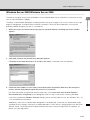
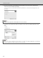
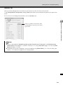
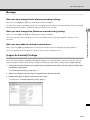
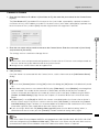
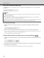
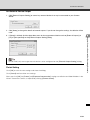
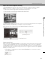
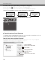
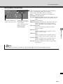
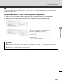
Windows Server 2003/Windows Server 2008
Therefore, a content block dialog box is displayed when you access pages such as the camera server's top
page or setting page, and commands cannot be carried out. To ensure normal operation, carry out the
procedure below to register the site as a trusted site.
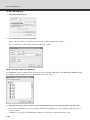
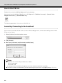
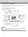
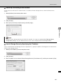
1. When you access the Camera Server top page using Internet Explorer, the dialog box shown at below
appears.
2. Click [Add], and then the [Trusted sites] dialog box appears.
If [Require server verification (https:) for all sites in this zone] is selected, clear the selection.
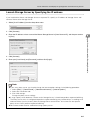
3. Check that the IP address of your camera server displayed in the [Add this Web site to the zone] box is
correct, and then click [Add] to register the camera as a trusted site.
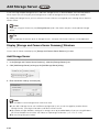
For more information on registration to the trusted sites, click [Learn more about Internet Explorer's
Enhanced Security Configuration] in the dialog box shown in step 1 and see the summary provided.
If you have enabled the [Windows Firewall] settings, please see the "Notes on Use with Windows XP" ( P.
1-12) and follow the instructions.
Additionally, even when a content block dialog box is not displayed, JavaScript may be disabled under
standard security settings, limiting the available operations in the camera's settings page or the VB-C500/
VB-C60 Viewer. JavaScript will be enabled automatically once trusted site registration is complete, so
please carry out registration.
1-13
1
System Overview
The default setting of security level of Windows Server 2003/Windows Server 2008 for the Internet or intranet
sites in Internet Explorer is [High].
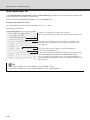
Notes on Operating Environment
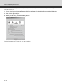
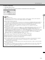
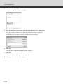
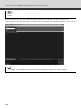
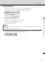
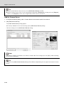
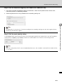
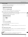
If the content block dialog box is not displayed, you can use the procedure below to display the dialog box for
adding a trusted site.
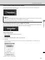
1. On the [Tools] menu in Internet Explorer, click [Internet Options] to display the [Internet Options] dialog box.
2. Next, click the [Security] tab.
3. Select [Trusted sites], and click the [Sites] button.
Settings for registering Trusted sites are now complete.
1-14
Notes on Operating Environment
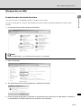
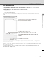
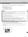
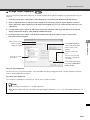
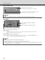
Windows Server 2008
1
Enable Sound to Use Audio Functions
System Overview
The sound function is disabled by default in Windows Server 2008.
To receive audio signals using the VB-C500/VB-C60 Viewer, follow the procedure below to enable sound
function.
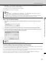
1. In the [Control Panel], click [Hardware and Sound].
Note
If the [Control Panel] is set to [Classic View], double click [Sound].
2. Next, click [Sound].
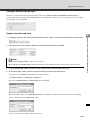
3. The [Audio Service Not Running] dialog box is displayed. Click [Yes].
4. Finally, the [Sound] dialog box is displayed. In the [Playback] tab, confirm that an audio device is installed. (If
no audio device is installed, check the user manual for your computer.)
1-15
Notes on Operating Environment
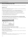
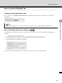
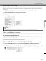
Windows Vista/Windows Server 2008
When using VK-64/VK-16 on Windows Vista Business/Enterprise/Ultimate/Windows Server 2008, pay attention
to the following restrictions.
Upgrade your PC
Please note that before upgrading your PC to Windows Vista/Windows Server 2008, you need to upgrade this
software to v2.2, if the version is older than v2.2.
If you upgrade your PC to Windows Vista/Windows Server 2008 before upgrading the software to v2.2, you will
not able to complete upgrade installation to v2.2. In this case, follow the procedure below.
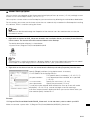
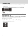
1. Right click on the [Storage Server Configuration] icon on the desktop, then choose [Properties].
2. Click the [Compatibility] tab and check the [Run this program as an administrator] check box.
3. Double click the [Storage Server Configuration] icon to launch the Storage Server Configuration tool.
4. Click the [Stop Storage Server] button in the [Storage server status].
5. Click the [Retry] button on the installer wizard for VK version 2.2.
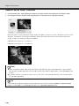
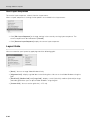
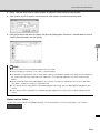
Warning dialog appeared when opening the Storage Server Configuration dialog
If User Account Control is enabled on Windows Vista/Windows Server 2008, the [User Account Control] dialog
will appear when you launch the Storage Server Configuration tool.
Click the [Continue] button to launch the Storage Server Configuration tool.
Notes for when the Windows Firewall Function is Enabled
When the Windows Firewall function is enabled, carry out the same settings as in the Windows XP section of
the Notes on Operating Environment.
Storage location of recorded video
On Windows Vista/Windows Server 2008, snap shots and video files cannot be saved into the Windows folder
or the Program Files folder on the system drive.
Shadow backup
You cannot use shadow backup of Windows Vista/Windows Server 2008. So, if once you delete a configuration
file of VK-64/VK-16, you cannot restore the file with shadow backup.( P. 7-7)
1-16
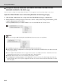
System Design Concept
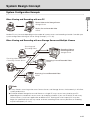
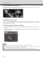
System Configuration Example
1
When Viewing and Recording with one PC
System Overview
Record video to the Storage Server
Storage Server
Display live and recorded video
Viewer
Load on PC may increase depending on the number of camera servers and recording schedule. Consider your
system configuration referring to "Server Sizing Concept" ( P. 1-20).
When Viewing and Recording with one Storage Server and Multiple Viewers
Receiving and
Recording Video
Storage
Server
Receiving Video and
Controlling Camera Server
Viewer
Viewer
Recording Video to
the Storage Server
Storage Server
Displaying Live and Recorded Video
Viewer
Displaying Live and Recorded Video
Viewer
Note
z If many Viewers accessing to the same Camera Servers and Storage Servers simultaneously, it will affect
system performance.
z Installation of both Storage Server and Viewer on a single PC may cause a heavy load on your PC
depending on the number of camera servers or recording schedule. If you use VK-64/VK-16 with many
Camera Servers, install each application on different PCs. Viewing with a low capacity PC may take
longer, the specified frame rate may not be achieved, recording frame rate may be lower, or recording
may be interrupted ( P. 1-21).
1-17
System Design Concept
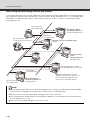
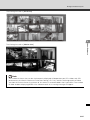
When using multiple Storage Servers and Viewers
One or more Storage Servers can be used on the same network and Viewer applications can be configured to
play video from more than one Storage Server. For each Viewer, Master Storage Server ( P. 1-19) needs to be
specified for saving information such as zones and locations of cameras, as well as saving Viewer layouts
created by the user.
Receiving and
Recording Video
Storage
Server
Recording video to
the Storage Server #1
Master Storage Server
Play back
recorded video
Receiving Video and
Controlling Camera Server
Viewer
Displaying live and recorded events
Viewer
Storage
Server
Displaying playback video from Storage Server 1
Recording video
to the
Storage Server #3
Storage Server
Viewer
Viewer
Displaying playback video
from Storage Server #2 and #3
Plays back
recorded video
Storage
Server
Receiving and
Recording video
Recording video to
the Storage Server #2
Storage Server
Multiple Storage Server can be
added to one network. Viewers can
receive video for playback from
more than one Storage Server.
Note
z You can operate VK-64/VK-16 with up to ten Storage Servers using any combination of VK-64 Storage
Server and VK-16 Storage Server. Up to 192 Camera Servers can be operated.
z Up to 10 Viewers can be connected to a Storage Server at the same time.
z If the Storage Server and/or Viewer are installed on multiple PCs, you need to purchase the necessary
license separately ( P. 1-6).
z You can not use multiple Storage Servers with VK-Lite.
1-18
System Design Concept
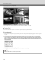
When using multiple Storage Servers
If multiple Storage Servers are being used, you should specify the Master Storage Server.
A typical multiple Storage Server arrangement is shown below.
1
er
iew
Master Storage Server
Play back Video to Viewer
Load Camera Server information
Load Zones and Locations
Load Viewer Layouts
Save Camera Server information
Save Zones and Locations
Save Viewer Layouts
ack
yb
Pla
o
ide
to V
V
Viewer
Pla
yb
ack
Vid
eo
Storage Server #3
to V
iew
er
A master storage server is a server, which viewers connect to in the first place. Master storage servers store
information about camera servers, locations, zones and viewer layouts, which range over multiple storage
servers. Viewers extract those information from a master storage server.
Note
z All of the Viewers within a system should use the same Storage Server as the Master Storage Server. This
makes it possible to use the same Zones, Locations, and Viewer Layouts in all of the Viewers.
z Ensure if the Storage Server and Viewer installed to the PC is operated with correct daytime setting
regularly. We recommend that you use NTP function to set the time for Storage Server automatically.
z Adjusting the time of Storage Server during recording may cause problems to the recording video.
z When multiple Storage Servers are operated, if the Storage Servers other than the Master Storage Server
are stopped, it takes time to display the Configuration and Preferences screen (approximately up to 30
seconds).
When using Viewer alone
The Viewer can be used by itself without connecting to the Storage Server. Although there are some restrictions
on functions such as recording and Event Search, Viewer-Only mode allows to view live videos.
1-19
System Overview
Storage Server #2
System Design Concept
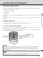
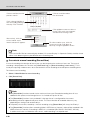
Server Sizing Concept
Determine your server configuration (components and the number of units) depending on 1) required hard disk
capacity and 2) video data volume per second.
1) Required hard disk capacity:
Consider the required hard disk capacity based on continuous recording
with fixed frame rate, resolution, and quantity.
2) Video data volume per second: If the video data volume per second by server exceeds values shown
below, you should consider multiple servers or review the recording
conditions.
Note
z Every operation environment of VK-64/VK-16 is different (due to different requirements and different
hardware specifications) and the figures provided below are just for the reference.
z Data volume per drive should be less than 2TB.
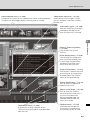
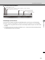
Approximate Video Data Volume per Second
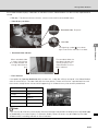
The recording performance of VK-64/VK-16 v2.2 is as follows.
• For dedicated Storage Server: Maximum amount of recorded data per server = 5.5 MB/sec or less
(when using SCSI, SAS disk)
JPEG
MPEG-4
VGA
QVGA
150 fps
440 fps
Total 44Mbit/sec.
• For Storage and Playback Server: Maximum amount of recorded data per server = 3 MB/sec or less
JPEG
MPEG-4
VGA
QVGA
90 fps
260 fps
Total 24Mbit/sec.
Note
Data-writing performance may be reduced than the approximate values given above depending on the
hard disk or the RAID card in the PC.
1-20
System Design Concept
Required Hard Disk Capacity
Determining Required Hard Disk Capacity
Determine the required hard disk capacity as follows.
1. Determine the required number of Camera Servers and required video data size.
2. Select the Image Quality of each Camera Server.
The video quality improves in proportion to the set value, but the data volume also becomes larger.
3. Determine the frame rate for recording video (i.e., the number of frames per second).
For general security purposes, 1 to 2 fps is common. Higher frame rate requires more hard disk space.
4. Determine the recording period per day and duration to retain data.
5. After determining the conditions above, calculate the required hard disk capacity due to the video data size
(in KB).
6. If you record audio, to calculate the amount of hard disk space required for the audio data. The data size for
recording audio is 8 KB/s regardless of the type of Camera Server.
When determining hard disk sizes it is important to take into account that there needs to be considered about
10 to 20% additional room.
Example 1: JPEG recording
• Using 16 Camera Servers (VB-C60) for recording,
• With each camera set to Medium Size for video data size and Image Quality set to 3 (data size per 1
frame: 12.5KB),
• Recording frame rate is set at 2 fps, and
• Data size per second is approximately 25 KB (= 12.5 KB x 2fps).
Although actual data size depends on objects shot by each Camera Server, this calculation assumes
the typical size shown above.
• Audio recording as also performed simultaneously on 2 of the Camera Servers.
For the above configuration, when JPEG images from 16 camera servers are being recorded continuously at 2
frames per second all day, every day, the required hard disk space is approximately 33GB per day (=25KB x
16 cameras x 60 seconds x 60 minutes x 24 hours = 34560000KB per day).
When audio is recorded by 2 camera server, the required hard disk space is approximately 1.3 GB per day (=8
KB x 2 units x 60 seconds x 60 minutes x 24 hours = 1382400 KB).
1-21
1
System Overview
The size of the images varies depending on the configuration of the Camera Server (the settings for Quality
and Resolution) and the complexity of the actual image.
System Design Concept
Example 2: MPEG-4 recording
• Using 8 Camera Servers (VB-C60) for recording,
• With each camera set to Medium Size (320 x 240) and Video Quality is set to 3,
• Recording frame rate is set at 30 fps, and
• Data size per second is approximately 150 KB.
Although actual data size depends on objects shot by each Camera Server, this calculation assumes
the typical size shown above.
For the above configuration, when MPEG-4 video from 8 Camera Servers are being recorded continuously at
30 fps all day, every day, the hard disk space required is approximately 99GB per day (=150KB x 8 cameras x
60 seconds x 60 minutes x 24 hours = 103680000KB per day).
* For the above figures please note that the bandwidth is calculated as 1000Kbps = 1Mbps, and the disk size
as 1024KB = 1MB.
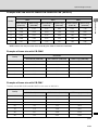
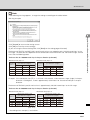
The following tables give some typical data sizes per frame (in kilobytes) for various combination of quality and
resolution values referring to a VB-C500VD, VB-C500D, VB-C60, VB-C300 and VB-C50i.
However the actual data size may be different from the data size in the table below depending on the weather
condition and complexity of the image. For example, images of an empty corridor would typically be smaller
than these values and images of an intricate pattern such as a crowded shopping mall may be larger than
these.
Example of frame size with VB-C500VD/VB-C500D/VB-C60* (JPEG)
Resolution
Quality
JPEG Small (160x120)
JPEG Medium (320x240)
JPEG Large (640x480)
1
3.5
9.6
27.5
2
4.0
11.0
31.7
3
4.4
12.5
35.8
4
5.6
16.4
47.8
5
15.8
52.7
171.4
(KB)
1-22
System Design Concept
Example of bit rate with VB-C500VD/VB-C500D/VB-C60* (MPEG-4)
Resolution and Frame Rate
10fps
15fps
1
30fps
MPEG-4 Medium
(320x240)
MPEG-4 Large
(640x480)
MPEG-4 Medium
(320x240)
MPEG-4 Large
(640x480)
MPEG-4 Medium
(320x240)
MPEG-4 Large
(640x480)
1
0.28
0.76
0.35
0.94
0.54
1.43
2
0.39
1.08
0.50
1.30
0.78
2.02
3
0.60
1.67
0.75
2.02
1.20
3.31
4
0.69
1.93
0.91
2.43
1.38
3.98
5
0.81
2.31
1.05
2.87
1.68
4.86
(Mbps)
MPEG-4 data size may increase when recording the video of strenuous movement.
Example of frame size with VB-C300*
Resolution
Quality
JPEG Small (160x120)
JPEG Medium (320x240)
JPEG Large (640x480)
1
3.2
8.8
24.2
2
3.7
10.2
28.3
3
4.1
11.5
32.0
4
5.3
15.4
43.2
5
15.5
52.8
170.6
(KB)
Example of frame size with VB-C50i*
The data size of VB-C50iR and VB-C50FSi is the same as VB-C50i's.
Resolution
Quality
JPEG Small (160x120)
JPEG Medium (320x240)
JPEG Large (640x480)
30
3.1
8.2
24.7
40
3.6
9.7
29.8
50
4.1
10.9
34.2
60
4.6
12.5
40.3
70
5.3
14.8
49.7
80
6.5
18.8
64.9
90
9.4
28.4
106.4
(KB)
1-23
System Overview
Quality
System Design Concept
* All of the data in the previous page sizes are only rough guide, and may increase or decrease depending on
the object being shot. Please be sure to confirm under the actual installation conditions before starting
operations. Select [Video Information] from the [View] menu of the Viewer (bundled with the Camera Server)
to check the data quantity per frame (VB-C300, VB-C50i, VB-C50iR, VB-C50FSi).
Note
Please note that data size may increase enormously when video quality is set to 100 with the VB-C50i,
VB-C50iR, VB-C50FSi, VB-C50Fi.
The size of audio data is 8 KB/s.
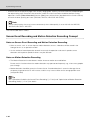
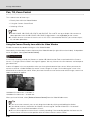
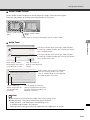
Sensor Event Recording and Motion Detection Recording Concept
Notes on Sensor Event Recording and Motion Detection Recording
• When an event, such as sensor input or motion detection, occurs, video data will be stored in the
Storage Server as an operation record.
• As the number of stored operation records increased, the operation and search speed at event
detection and response speed of viewers may be affected.
Notes on Motion Detection Recording
• The Motion Detection function detects motion where no motion occurred before.
Do not use this function where the motion detection may operate too frequently, e.g., where many people
pass through.
• Motion detection should be set on the Camera Server. If motion detection is set on the Storage Server,
the processing load on the PC will increase, and this may have an effect on the storage performance.
(except VB-C300)
Tip
See "Operational Guideline for Sensor Event Recording" ( P. 6-6) and "Optimization of Motion Detection
Recording (Index)" ( P. 6-7) for details.
1-24
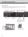
System Design Concept
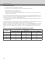
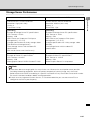
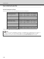
Storage Server Performance
<Case 2: in JPEG>
Camera Servers: 24 units of VB-C60
Resolution: High (640 x 480)
Quality: 3
Frame Rate: 10 fps
Camera Servers: 48 units of VB-C60
Resolution: Medium (320 x 240)
Quality: 3
Frame Rate: 1 fps
[Recording]
Example of Storage Server PC specifications
CPU: Pentium 4 3GHz
Memory: 1GB
HDD: Please see "Important: Disk Space
Management" ( P. 3-17)
(Sample specifications for 3-day storage: about
708 GB for each Storage Server)
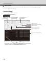
Three Storage Servers with the above PC
specifications
(one master Server, two slave Servers)
[Recording]
Example of Storage Server PC specifications
CPU: Pentium 4 3GHz
Memory: 1GB
HDD: Please see "Important: Disk Space
Management" ( P. 3-17)
(Sample specifications for 14-day storage: about
693 GB)
One Storage Server with the above PC
specifications
[Live View, Recorded Video Playback]
Example of Viewer PC specifications
CPU: Pentium 4 3.8GHz
Memory: 1GB
Video graphics board: NVIDIA Quadro FX 1400
[Live View, Recorded Video Playback]
Example of Viewer PC specifications
CPU: Pentium 4 3.0GHz
Memory: 1GB
Video Graphics Board: On-chip board
1
System Overview
<Case 1: in JPEG>
Note
z These data above are rough guide. As many factors can influence the actual performance possible
(including networking equipment, disk write speed, complexity of camera image, etc), the actual
performance of VK-64/VK-16 recording in a specific installation will vary. Please be sure to confirm under
the actual installation conditions before starting operations.
z If there are many registered Camera Servers, it is recommended that you use two or more PCs or
configure to use the Layout frequency.
1-25
System Design Concept
Notes on Storage Server Operation
It is recommended to use the Storage Server exclusively for the VK-64/VK-16.
Be sure to avoid the following forms of operation.
• Using the Storage Server with a Web Server
As Storage Server, you cannot use a PC where Web server software such as Windows standard IIS
(Internet Information Server) or Apache has been already installed.
Since the Storage Server uses the HTTP protocol to communicate with the Camera Server, therefore it
may not work properly if other Web applications exist on the same platform.
The HTTP port number used by the VK-64/VK-16 should be fixed to "80".
• Using the Storage Server with a Database Server (e.g., SQL Server, Oracle)
If the hard disk is heavily loaded in database processing, recording may not work normally. Conversely,
the database server may be affected by the VK-64/VK-16 when it need hard disk performance to
complete its task.
• Using the Storage Server with a File Server
Accesses to the hard disk may be too frequent and recording may not work normally. Also, the disk
capacity for the VK-64/VK-16 may run short.
• Using the Storage Server with other applications
The processing load of other applications may have a negative effect on the storage performance.
This software uses 3 ports: TCP 80/TCP 9080/TCP 10080. If you are running another application which
uses the same ports on your PC at the same time, please use another port.
Notes on Viewer Sizing
Consider the following points when selecting the PC for viewer (installed).
• Live-video viewing and recorded video playback performance of the VK-64/VK-16 largely depends
on the CPU and graphics board performance on the PC. The CPU performance affects image
capturing and video data generation, and the graphics board performance affects image drawing.
See the following example when selecting the PC for the viewer installed.
In this example, the OS is Windows XP Professional.
1. CPU: Pentium 4 3.0GHz, memory: 1GB, graphics board: Quadro FX570
When using the VB-C60 with Resolution=340 x 240 and Quality=3:
Total frame rate:
JPEG image---Max. 220 fps
MPEG-4 video---Max. 180 fps
2. CPU: Pentium 4 3.6GHz, memory: 1GB, graphics board: Quadro FX1700
When using the VB-C60 with Resolution=340 x 240 and Quality=3:
Total frame rate:
JPEG image---Max. 260 fps
MPEG-4 video---Max. 210 fps
1-26
System Design Concept
3. CPU: Pentium 4 3.8GHz, memory: 1GB, graphics board: Quadro FX1700
When using the VB-C60 with Resolution=340 x 240 and Quality=3:
Total frame rate:
JPEG image---Max. 280 fps
MPEG-4 video---Max. 240 fps
1
z Note that the total frame rate above varies depending on the combination of the PC and graphics board.
It is also affected by other applications (e.g., anti-virus application) running on the same PC.
z When displaying MPEG-4 video in VGA, the maximum frame rates are the one-forth of the above frame
rates.
Network Bandwidth Concept
You should consider the network bandwidth when recording video or viewing live video from the network
camera.
The network bandwidths should be calculated separately for recording and live viewing.
Example:
With one recording server (QVGA, 1 fps) and two live viewing servers (QVGA, 5 fps):
• Bandwidth for recording
12.5 (KB/frame) x 1 (frame/sec) x 8 (bits) = 100 Kbps
• Bandwidth for live viewing (per server)
12.5 (KB/frame) x 5 (frame/sec) x 8 (bits) = 500 Kbps
Therefore, required network bandwidth is calculated as follows:
100 Kbps x 1 + 500 Kbps x 2 = 1100 Kbps = Approx. 1.1 Mbps
Note that the line speed unit is bps (bits per second).
1-27
System Overview
Tip
z The total frame rate is calculated as: Number of Camera Servers in the Viewer window x Frame rate. That
means, with 10 Camera Servers and 10 fps frame rate, the total frame rate is 100 fps.
VK-Lite
VK-Lite is bundled with VB-C500VD, VB-C500D and VB-C60. This is a simplified version of the Network Video
Recorder VK-64/VK-16. The differences in functionality between the VK-64/VK-16 and VK-Lite product versions
are summarized below.
Functional Limitations in VK-Lite
• The maximum number of cameras that can be registered is 4 units.
• It is recommended that 8 or less video windows are displayed in the Viewer Window (a warning is
displayed if 9 or more video windows are displayed).
• The maximum frame rate is as follows.
Video recording
5 fps or less (JPEG)
Record now
Fixed at 5 fps
• The reduce frame rate under high load is fixed on.
• The maximum file size is fixed at 1 GB per day, and cannot be changed.
• The supported cameras are as follows.
VB-C500VD, VB-C500D, VB-C60, VB-C300, VB-C50i, VB-C50iR, VB-C50Fi, and VB-C50FSi
• The VK-Lite Viewer cannot connect to VK-64/VK-16 Storage Server.
• The VK-64/VK-16 Viewer can connect to VK-Lite Storage Server.
However, older versions of the VK-64/VK-16 Viewer cannot connect to VK-Lite Storage Server.
Note
z You cannot connect to the following cameras.
VB-C10, VB-C10R, VB150
1-28
VK-Lite
Functions that cannot be used in VK-Lite
• Storage Server
1
• Recording to NAS
System Overview
• MPEG-4 recording
• Motion detection recording
• Sensor recording
• A Special day recording
• Send mail on event function
• Customization of event priority
• Connection via HTTP proxy
• Remote trigger
• VK Viewer
• Layout frequency
• Simultaneous monitoring of multiple storage servers
• Designated schedules
• Connection via HTTP proxy
• Registration of slave storage servers
• Viewer control API
Tip
Functions that cannot be used with the VK-Lite Viewer or VK-Lite Server are indicated by the following
marking in the text.
Other
• Windows Vista Home Premium is also supported in addition to the VK-64/VK-16 system environments
( P. 1-10).
• It is possible to upgrade VK-Lite to VK-64/VK-16.
1-29
Specification Comparison of VK-64/VK-16 and VK-Lite
This section explains what you need to know before using the VK-64/VK-16, and the required operating
environment and considerations when designing a system.
Type
Main functional limitations
VK-64/VK-16 v2.2
VK-Lite v2.2
Max. number of camera servers
64 / 16
4
VB-C500VD, VB-C500D,
VB-C60, VB-C300,
VB-C50 series,
VB-C10/R, VB150
VB-C500VD, VB-C500D,
VB-C60, VB-C300,
VB-C50 series
✔
✔
JPEG, MPEG-4
JPEG only
30 fps*1
5 fps
Normal Schedule recording
(Continuous recording,
Sensor event recording,
Motion detection recording)
Special Day Schedule
recording Manual recording
Normal Schedule recording
(Continuous recording)
Manual recording
available
32~1024MB, 1~24 hours
Fixed
1GB/day (1024MB)
999 weeks*1
12 weeks (90 days)
Audio recording / playback
✔
✔
Recording to NAS servers
✔
–
–
Following functions are
unavailable.
z Sending mail when an event
occurs
z Customizing priorities of
events
z Connection via HTTP proxy
z Remote trigger
JPEG, MPEG-4
JPEG, MPEG-4
30 fps*1
30 fps*1
Unlimited*1
8 or less is recommended.
Two-way audio
✔
✔
Registration of multiple storage
servers*2
✔
–
Layout Sequences*3
✔
–
Other functional limitations
–
Camera
Available camera servers
server
connection
Automatic camera server search
Recording format
Max. recording frame rate
Video recording mode
Max. file size setting
Storage
Server
Max. retained history of
recorded video
Other functional limitations
Live video format
Max. displaying frame rate
Max. number of video windows
on the viewer
Viewer
Following function is
unavailable.
z Connection via HTTP proxy
*1 Operational limits apply depending on the number of cameras, the PC performance and hard disk capacity,
and the amount of network traffic.
*2 In case of using VK-64/VK-16 with multiple storage servers, you can unify management of cameras registered
to each storage server and the recorded data, if you set one master storage server. When connecting to each
storage server using VK-Lite viewer, you need to switch connection one by one.
*3 Layout Sequences is a function to switch displayed viewer windows at set intervals.
1-30
Installation
Chapter Overview
This chapter explains how to install VK-64/VK-16.
Setting up the Camera Servers
Firstly set up Camera Server. For connection in detail, see the manual for Camera Server.
Install the Storage Server and Viewer
Note
Before the installation, read Chapter 1 and "Preparation and Precaution" ( P. 2-7) carefully.
When you install VK-64/VK-16, icons for two applications composing VK-64/VK-16 is created on the desktop.
Tip
z See Chapter 3 for how to use the Storage Server.
z See Chapter 4 for how to use VK Viewer.
z The following icons are displayed if VK-Lite is installed.
2-2
Installation Procedures
Note
z Types and number of license has been determined for VK-64 and VK-16. If you want to add the Storage
Server or Viewer, you need to purchase necessary software ( P. 1-6).
z The hard disk where the software will be installed should be formatted in the NTFS ( P. 2-7).
Installation
Start up the Installer
1. To start installing VK-64/VK-16, insert the installation CD-ROM into the CD drive, and then the Welcome
screen appears. Click [Next] to continue.
If the installer does not automatically launch, open the CD-ROM directory in Explorer and double-click
v22setup.exe. Then, installation process starts.
To start installing VK-Lite, double-click VKLiteInstall.exe in the APPLICATIONS folder on the VB-C500VD/
VB-C500D/VB-C60 Setup CD-ROM.
2. The [Software License Agreement] screen appears. Read the agreement carefully.
Click the radio button, [I accept the terms in the license agreement] and then click [Next] to continue.
2-3
Installation Procedures
3. Enter your License Key(s) and click [Next] to install VK-64/VK-16. Your License Key is indicated on the
"About License Key" included in the package.
* VK-Lite that comes with VB-C500VD, VB-C500D and VB-C60 has a license for one Storage Server and
one Viewer.
Tip
No License Key registration window appears for VK-Lite installation.
4. Depending on your entered License Key for VK-64/VK-16, one or both of the following applications shown
below:
• Viewer
• Storage Server
Tip
You cannot change the application to be installed in this window. To change the application, you need to go
back to the registration window and enter the license key again.
2-4
Installation Procedures
For VK-Lite, both of the following applications are installed.
• Viewer
• Storage Server
When you need to install either one of the above, right-click on the application icon which you will not install,
and choose [This feature will not be available].
Click [Next] to continue.
Tip
Click [Space] and then a list of drives is shown. And also the amount of required disk space for the
installation of VK-64/VK-16/VK-Lite.
5. Click [Install].
The installation process begins, and a progress bar is displayed.
6. When the [InstallShield Wizard Completed] screen is displayed, click [Finish].
Installation is now completed.
2-5
Installation
It is recommended not to change the designated installation directory. Click [Change] to choose another
installation path if necessary, and then select the directory to install the software.
Installation Procedures
Upgrade from Version 1.0, 1.1, 1.2, 1.3, 1.4, 2.0 and 2.1
If you upgrade the Viewer from an older version, all the settings are taken over to the new version and video
data recorded with older version can be played back with Version 2.2. It is recommended to confirm your
settings after the upgrading.
For the details, see "Upgrade VK-64/VK-16" ( P. 8-3).
Note
z If you are using VK-64/VK-16 with NAS server, you need to set up log-on settings again after upgrading
VK from v1.3, 1.4, 2.0, 2.1 to v2.2.
z Version 2.2 of the Viewer is able to connect to versions 1.2, 1.3, 1.4, 2.0 and 2.1 of the Storage Server. All
of the versions are able to be selected as the Master Storage Server. However, the following functions are
specific to version 2.2, and cannot be used on previous versions of the Storage Server.
• VB-C500VD registration
• Audio-related settings (Can be used with version 2.0, 2.1 Storage Servers)
• Retrieving summary information from a Storage Server (Can be used with version 2.0, 2.1 Storage
Servers)
z Viewer v2.2 cannot connect to the Storage Server v1.0 or v1.1.
z Older version of Viewer cannot connect to the Storage Server v2.2.
z Version 2.2 of the Storage Server can continue to use the video data and storage settings from previous
versions.
z When upgrading from any versions before 1.1.2.27, you need to set motion detection ( P. 4-46) again.
You can check your version information from the version information ( P. 10-5) of the Storage Server and
the Viewer.
2-6
Installation Procedures
Preparation and Precaution
Use NTFS-formatted hard disk
The hard disk where the software will be installed and video data will be stored should be formatted in the
NTFS.
Installation
You can convert the current hard disk into the NTFS format using the following command at the command
prompt.
convert <Name of the drive>:/fs:ntfs
Example:
To convert Drive C into the NTFS format:
convert c:/fs:ntfs
Tip
Select [All Programs], [Accessories], and [Command Prompt] from the [Start] menu to display the
command prompt. If you press the [Enter] key following the command shown above, a series of questions
appears, then conversion starts. Reboot the PC after the process completes conversion. Any data on the
hard disk is not lost by conversion.
Stop other applications
You should stop other applications including anti-virus program before starting installation.
2-7
Installation Procedures
2-8
Storage Server
Configuration Reference
Chapter Overview
The Storage Server can record videos and events (sensor input and motion detection) data from multiple
camera servers.
This chapter explains how to set the installed Storage Server to use the storage server.
Use the [Storage Server Configuration] dialog to set the Storage Server.
In the [Storage Server Configuration] dialog, you can configure settings for disk management, event
management, event notification, and user management.
[Settings] Tab
In the [Settings] tab, specify the Storage Server name, Proxy Server, and recording options.
[Event] Tab
You can set the Storage Server to send an e-mail to the user when an event has occurred.
In the [Event] tab, specify the priority for each event type.
[Event Notification] Tab
In the [Event Notification] tab, configure the settings for sending an e-mail when an event has occurred.
[User Management] Tab
In the [User Management] tab, add users and assign privileges to them.
3-2
[Storage Server Configuration] Dialog
How to Start-Up
Double-click the [Storage Server Configuration v2.2] desktop icon.
If the [Require authentication when starting this tool] is selected ( P. 3-27), the [Login] dialog appears.
In this case, enter your user name and password, and click [Login].
If User Account Control is enabled on Windows Vista/Windows Server 2008, the [User Account Control] screen
will appear.
In this case, click the [Continue] button.
Note
To configure the Storage Server, you should log into Windows with the Windows Administrator privilege.
3-3
Storage Server Configuration Reference
Alternatively, from the Windows [Start] menu select: [All Programs] > [WebView Livescope] > [Network Video
Recorder VK Series v2.2] > [Storage Server Configuration v2.2].
[Storage Server Configuration] Dialog
Screen Configuration
The [Storage Server Configuration] dialog has the following four tabs.
• [Settings] Tab
• [Events] Tab
• [Event Notification] Tab
• [User Management] Tab
[Settings] Tab
In the [Storage Server Configuration] dialog, [Settings] tab allows you to configure these items below.
• Storage Server Name
• Proxy Server
• Recording options
Click the title bar icon and select [About Storage Server
Configuration] or right-click the title bar to display the
[About Storage Server Configuration] box.
Enter name for your Storage Server.
Enter proxy address for connecting to Camera Servers.
Set [Maximum retained history], [Maximum file size / duration] and
[Low Disk Space Warning Level].
Set [Maximum disk space used] for each device.
Also, add or remove network drives.
Storage Server status indicator. [Start Storage Server] and
[Stop Storage Server] start and stop the Storage Server.
Use an account other than the [Local System account] to log onto
the Storage Server to enable connection to the network drive.
Click [Apply] to save changes when you modify settings from
each tab.
Tip
VK-64/VK-16 can save video data on the network drive.
3-4
[Storage Server Configuration] Dialog
[Events] Tab
You can set the Storage Server to send an e-mail to the user when an event has occurred.
In the [Storage Server Configuration] dialog, [Events] tab allows you to configure the priority for types of the
event.
E-mails are sent according to the priorities set in the [Events] tab.
Storage Server Configuration Reference
Select a suitable event priority from
the drop-down menu for each event
type listed.
Note
z Events associated with [Recording engine started], [Data file set], [User log in], and [Failed to map a
network drive] do not appear in a Viewer's Timeline ( P. 5-48), [Live Events Log] ( P. 5-56), or [Event
Search] Dialog ( P. 5-58).
z The priority of an event created by a manual recording using [Record Now] ( P. 5-52) will always be
Priority 1. It cannot be changed from this dialog above.
3-5
[Storage Server Configuration] Dialog
[Event Notification] Tab
In the [Storage Server Configuration] dialog, [Event Notification] tab allows you to configure the setting of the
e-mail sent to the user when the event occurs.
E-mails are sent according to the priorities set in the [Events] tab.
Example event notification e-mail
An event of priority 3 occurred on 12/05/2006 at 15:15:17 +1000.
Parking Lot 1: Sensor on
Enable e-mail notification and select a priority.
Events of that priority and above will lead to notification emails.
Enter the e-mail subject line, for example, "Immediate Actio
Required". Enter the address of the recipient and enter your
from address.
Enter a Host Name or IP address and Port Number of
mail server for outgoing mail.
Enable authentication (POP-before-SMTP) for connection and
enter [User Name], [Password] and [POP Server] details.
If this is enabled, the Storage Server will attempt to perform a
POP login before sending e-mail that may be required for some
SMTP servers.
Tip
You can only register one e-mail address in the To Address field.
If you want to send the e-mail to multiple addresses, use a group address.
3-6
[Storage Server Configuration] Dialog
[User Management] Tab
In the [Storage Server Configuration] dialog, [User Management] tab allows you to set up users and their
privileges.
[User Management] tab allows you to configure the following privileges:
• Administrator
• Not Administrator (Operator)
Storage Server Configuration Reference
Administrator has access to the Viewer including Camera Server setup, recording schedules and Viewer
setup.
Check to enable user to have Administrator privileges
(full access to configuration functions).
Use [Add] to add users to this field.
There is no limit to the number of users you can add.
Check [Require authentication when starting this tool] box
if needed.
Click [Apply] to save changes.
Users who have Operator Status cannot configure, register and change Camera Servers, or configure and
change recording schedules.
By default, a user called "admin" is created. The password is "NVR". It is strongly recommended that this should
be changed after installation.
It is necessary to set up users on all Storage Servers. A particular user should be set up to have the same
password on each Storage Server.
3-7
Set the [Settings] Tab
In the [Storage Server Configuration] dialog, [Settings] tab allows you to configure the items below.
• Storage Server name
• Proxy Server
• Settings for storing recorded video
• Start and stop of Storage Server
• Logon Account for Storage Server
How to Display the [Settings] Tab
Double-click the [Storage Server Configuration] desktop icon.
The [Storage Server Configuration] dialog appears and the [Settings] tab is displayed.
3-8
Set the [Settings] Tab
How to set the [Settings] Tab
Changing the Storage Server name
Enter a new name in [Storage Server Name] to change the Storage Server name (You can use up to 20
characters).
Storage Server Configuration Reference
Tip
It is recommended to use an easy-to-understand name if you are using multiple Storage Servers.
Enter the Storage Server Proxy Address
If the Storage Server needs to access Camera Servers via proxy server, you may need to configure proxy
settings.
*
See P. xiii if you use a proxy server.
1. In the [Storage Server Ploxy] field, tick the [Enable the following ploxy server] box.
2. Enter the [Proxy server] address and [Port].
For more information on proxy server usage, contact your Camera Server administrator.
3-9
Set the [Settings] Tab
Enter [Recorded Video Settings]
1. [Maximum retained history] - Check the [Maximum retained history] option and enter a value from 1 to 999
and then select [Days] or [Weeks] from the pull-down menu.
2.
[Maximum file size / duration] - Check the [Maximum file size / duration] option, enter a value, and select
[MB] or [Hours]. You can enter 32 - 1024 for [MB] and 1 - 24 for [Hours]. If you do not enter a value, 1024 MB
or 24 hours is used for the Maximum file size/duration value.
3. [Low disk space warning level] - Enter a percent value.
When the remaining space falls below the specified value, the event will be displayed and a notification will
be e-mailed ( P. 3-5, P. 3-23).
4.
[Reduce recording frame rate when disk is under high load] - When disk is highly loaded, recording frame
rate is temporarily reduced to prevent the recording from stopped. See Chapter 6 for details. This function is
available for JPEG video recording. It cannot be used for MPEG-4 video recording (VB-C500VD, VB-C500D,
VB-C60).
Tip
If [Reduce recording frame rate when disk is under high load] is selected, you will receive an event
notification such as "Effective Recording rate (<recording rate before change> <recording rate after
change> %)" when the recording frame rate drops.
Ex. Effective Recording rate (100.0 90.0 %)
Note
When the free disk space has fallen below the value specified in the [Low disk space warning level] field, an
event occurs and an event notification mail is sent. Also, if the used disk space exceeds the value specified
in the [Maximum disk space used] field, recorded video will not be saved until the required free disk space
is secured. See P. 3-17 for the disk space management.
3-10
Set the [Settings] Tab
Select [Disk Drive Settings]
1. [Drive] - Select the disk drive to configure, from the drop-down menu.
2. [Maximum disk space used] - Check the box and enter a value in Megabytes (MB) or Gigabytes (GB), for
example, "50".
This establishes the maximum disk space used for all video files on the specified drive.
The added network drive is shown on the [Drive] drop-down menu.
4. [Delete Network Drive] - Delete an added network drive.
Adding/Removing a Network Drive
By adding a network drive, you can save recorded video data on a network drive such as NAS (Network
Attached Storage) in addition to the internal HDD.
If you add a network drive in the [Storage Server Configuration] window, the drive will be added to the list of the
pull-down menu of the [Add Camera Server] and [Edit Camera Server] dialog ( P. 4-18, P. 4-24).
Note
Use recommended NAS servers with Windows Storage Server 2003 or Windows Storage Server 2003 R2.
Tip
When using the Storage Server with the local system account, the [Add Network Drive] and [Delete Network
Drive] buttons are disabled.
3-11
Storage Server Configuration Reference
3. [Add Network Drive] - Add a disk drive on the network used as the network drive.
Set the [Settings] Tab
To add a network drive
1. Click [Add Network Drive].
2. The [Add Network Drive] dialog appears.
Select a drive to add as a network drive and enter a path assigned to the drive.
You can also enter a path automatically by selecting a folder.
When selecting a folder with [Browse]
Click [Browse], select a folder where you want to save recorded video data in the [Browse for Folder] dialog.
Click [OK] to enter the path of the selected folder in the path field.
3. Enter the user name and password to access the network drive in the respective fields, and click [OK].
Be sure to use different user name and password from the logon user name and password for the local
system account.
If addition is successful, the added drive appears on the drive selection pull-down menu.
3-12
Set the [Settings] Tab
To remove a network drive
1. Click [Delete Network Drive].
2. Select a network drive and click [OK] to delete the selected drive from the Storage Server.
z About Network Drive
VK-64/VK-16 can record videos on a drive on the network. The drive type is shown at the head of the
[Drive] drop-down menu as "Internal disk: [local], Network drive: [network]".
z About Video Recording Operation
If disk space is not enough to cover the specified value configured with [Maximum disk space used], the
retained duration of recorded video may be shorter than the specified period or the recording may be
temporarily stopped. Please be sure to perform sufficient tests before starting operations.
z For details about disk space management on the Storage Server, see "Important: Disk Space
Management" ( P. 3-17).
z Windows does not allow a user who has logged in with a [local system account] (used for normal service
management) to add a network drive. The [Add network drive] and [Delete network drive] items are
disabled while you are logging into Windows with a [local system account]. To set the network drive, click
[Stop Storage Server] to stop the Storage Server, and click the [Logon settings] and switch to an account
which is allowed to use the network drive (i.e., account with Windows' Administrator and [Logon As
Service] privileges). see "[Logon As Service] Privilege" ( P. 3-15).
z You cannot use a UNC path or removable disk when adding a network drive.
z If you add or delete a network drive, the Storage Server program will reboot.
z Multiple Storage Servers cannot use the same network drive simultaneously.
z Single network drive cannot allocate to multiple drivers.
z If the selected network drive cannot be accessed because the network is disconnected, the selected
drive is powered off, or you entered a wrong path, the following error message will appear.
"Network path cannot be found."
z While the network drive is not operating (e.g., due to network disconnection), video will not be recorded
until the drive recovers.
z If a storage server is booted when the storage server is unable to connect to a NAS server, video image
data won't be written to or recorded data won't be read from NAS server even after the NAS server
recovers. In such case, reboot the storage server.
3-13
Storage Server Configuration Reference
Note
Set the [Settings] Tab
Start or Stop the Storage Server Program
Click [Stop Storage Server] to stop the Storage Server.
Click [Start Storage Server] to start the Storage Server.
Note
If you need to stop the Storage Server Program, you should inform all users connected to the storage server
before you stop the storage server.
Change the [Logon settings]
1. If you need to log onto the Storage Server with another account when using a network drive, click [Stop
Storage Server].
After the Storage Server stops, click [Logon settings].
The [Log on as] dialog appears.
2. If you are logging onto the Storage Server with a [Local System account], select [Local System account]. If
you are log onto the Storage Server with another account, enter the account name in [This account] and
password in [Password] and confirm password.
3. Click [OK].
4. Click [Start Storage Server] to start the Storage Server with the specified account.
Note
If you are using VK-64/VK-16 with NAS server, you need to set up log-on settings again after upgrading VK
from v1.3, v1.4, v2.0 or v2.1 to v2.2.
3-14
Set the [Settings] Tab
Message
When you have changed items affecting recording settings:
When you click [Apply] or [End], the following message will appear.
"An item which affects recording settings was changed. Please inspect the "Record Settings Summary" dialog
on the Recording Schedules window to check the effects of the change."
Storage Server Configuration Reference
When you have changed the [Maximum retained history] setting:
When you click [Apply] or [End], the following message will appear.
"The new retained history settings may result in the deletion of some existing video files. Do you wish to
continue?"
When you have added or deleted a network drive:
When you click [Apply] or [End] before restarting the storage server, the following message appears.
"Drive use settings have changed. Do you wish to restart the recording server?"
[Logon As Service] Privilege
When you want to add the [Logon As Service] privilege to an existing Windows account so that you may be
able to configure network drive settings, perform the following steps before configuring the [logon settings].
1. Click [Control Panel], [Performance and Maintenance], [Administration Tool], and [Local Security Policy] from
the Windows' [Start] menu.
The [Local Security Policy] dialog appears.
2. Select [Local Policy] and [User Rights Assignment] from the tree to the left.
3. Double-click [Logon as Service] from the list to the right.
The [Log on as a service Properties] dialog appears.
3-15
Set the [Settings] Tab
4. Click [Add User or Group].
The [Select Users or Groups] dialog appears.
5. Enter the Windows account name in the [Enter the object names to select] field.
Enter or change the object name, location, and detail settings as required.
Be sure to enter a Windows account with Administrator privileges.
6. Click [OK].
The [Log on as a service Properties] dialog reappears.
7. Click [OK].
The [Local Security Settings] dialog reappears.
8. Close the [Local Security Settings] dialog.
3-16
Important: Disk Space Management
Disk Space Management Level
The Storage Server monitors the remaining disk space to check the current disk space management level and
takes a measure according to the current level.
1. [Low disk space warning level]
2. Threshold Level
3. Limit Level
The Storage Server calculates the values for Threshold Level 2. and Limit Level 3. based on various conditions
and settings.
Handling at Each Level
The Storage Server performs the following when the disk space reaches each level.
In case of [Low disk space warning level]
The Storage Server generates an event when the disk space available for recording (i.e., free space from the
Maximum disk space used value) has fallen down to a certain level.
If the [Maximum disk space used] field is not set, the entire drive capacity of the drive specified in the [Drive]
field is considered to be the maximum disk space used.
Event Notification
[Maximum disk
space used]
Disk space on
drive <Drive> :
warning
Warning Level
Note
The event notification e-mail is sent when the priority specified for the [Low disk space warning level] option
in the [Events] tab of the [Storage Server Configuration] dialog is equal to or higher than the priority
specified in the [Event Notification] tab. See P. 3-21 and P. 3-23 for how to set the [Events] and [Event
Notification] tabs.
Tip
Event notification allows early control by an administrator to avoid problems due to running out of disk
space (for example, removing unnecessary recording schedules).
3-17
Storage Server Configuration Reference
Administrator can set the [Low disk space warning level] 1. using the Low disk space warning level field in the
[Settings] tab.
Important: Disk Space Management
In case of Threshold Level
The Storage Server continues recording video; however, it starts deleting the video files from the oldest one,
and generates an event.
Starting : deleting files
on drive <drive> due to
low disk space
[Maximum disk
space used]
Delete from
the oldest file
Event Notification
Threshold Level
Tip
Old video files may be deleted even if these are within the [Maximum retained history] period.
However if the oldest file is currently used in the Viewer (for example for playback of recorded video), it
would not be deleted and the next oldest file will be deleted instead. Deletion will continue until the free
space rises above this threshold again.
See Chapter 7 for saving files.
In case of Limit Level
The Storage Server stops recording video when the free disk space goes down to this level, and generates an
event.
When the free disk space increases above this level by deleting old video files, the Storage Server resume
recording video and generates an event.
Stopping : suspension of
recording on drive <Drive>
due to low disk space
[Maximum disk
space used]
Delete from
Stop Recording the oldest file
Limit Level
3-18
Event Notification
Important: Disk Space Management
[Low disk space warning level] Calculation Method
The [Low disk space warning level] occurs when the Storage Server fulfills the condition 1. or 2. below.
1. When the Storage Server disk space used exceeds the following value:
M x (100 - A)/100
M: Value for [Maximum disk space used]
A: Value for [Low disk space warning level]
2. When free disk space falls below the following value:
Disk capacity x A/100
A: Value for [Low disk space warning level]
Example: In case of the value for disk capacity is 80 GB and the value for [Low disk space warning level] is
10%, the Storage Server reaches the [Low disk space warning level] when the remaining free disk space
becomes 8 GB or less.
Tip
If other applications are also using the same hard disk, you need to review the condition 2). Even if the
Storage Server uses a small quantity of disk space, it may reach the [Low disk space warning level]
because other applications has consumed disk space.
Threshold Level Calculation Method
The Threshold Level occurs when the Storage Server fulfills the condition 1) or 2) below.
1. When the Storage Server disk space used exceeds the following value:
a. When [Maximum disk space used] is set 384 MB or more,
[Maximum disk space used] - 96MB
b. When [Maximum disk space used] is set 384 MB or less,
[Maximum disk space used] x 3/4
2. When free disk space falls below the following value:
(Number of Camera Servers + 1) x 32MB + 96MB
3-19
Storage Server Configuration Reference
Example: In case of the value for [Maximum disk space used] is 100 GB and the value for [Low disk space
warning level] is 10%, the Storage Server reaches the [Low disk space warning level] when the remaining
free disk space becomes 10 GB or less.
Important: Disk Space Management
Limit Level Calculation Method
The Limit Level occurs when the Storage Server fulfills the condition 1. or 2. below.
1. When the Storage Server disk space used exceeds the following value:
[Maximum disk space used]
2. A When free disk space falls below the following value:
(Number of Camera Servers + 1) x 32MB
Calculation Example for Each Level
Disk Drive
Disk Capacity
Free Disk Space
Max. Disk Space Used
Camera Server No.
C Drive
100GB
50GB
40GB
19 units
D Drive
200GB
200GB
200GB
19 units
The following is a table of values for each level calculated based on the examples above.
Disk Drive
Low Disk Warning Level
Threshold Level
Limit Level
C Drive
1. 40GB x (100-10) / 100=36GB
2. 100GB x 10 / 100=10GB
1. 40GB-96MB=39.904GB
2. (19+1) x 32MB+96MB=736MB
1. 40GB
2. (19+1) x 32MB=640MB
D Drive
1. 200GB x (100-10) / 100=180GB
2. 200GB x 10 / 100=20GB
1. 200GB-96MB=199.904GB
2. (19+1) x 32MB+96MB=736MB
1. 200GB
2. (19+1) x 32MB=640MB
Note
z Threshold Level can be used as a protective level to avoid achieving Limit Level. It is recommended that
you take measures when [Low disk space warning level] event notification is generated, such as deleting
unnecessary video files.
z Storing video data above the Threshold Level increases load over the Storage Server and may cause
recording interruption.
It is strongly recommended to use the Storage Server below the Threshold Level.
z See "Operation Guideline for Recording and Viewing" ( P. 6-5) for detailed of operation.
z If e-mail notification for each levels is selected, the system can be configured to provide e-mail
notifications when one of these levels is reached ( P. 3-23).
z The requirements of Threshold Level may be achieved before the requirements of [Low disk space
warning level] are satisfied, depending on circumstances. For example, large numbers of cameras with
limited disk capacity may bring a larger value for (Numbers of camera +1) x 32 MB + 96 MB, compared
with the value of Disk capacity x [Low disk space warning level]/100.
3-20
Set [Events] Tab
[Events] tab in the [Storage Server Configuration] dialog allows you to specify event priorities.
If you have configured the event notification e-mail settings, e-mails are sent based on the priorities set in the
[Events] tab.
How to Display the [Events] Tab
Double-click the [Storage Server Configuration] desktop icon.
The [Storage Server Configuration] dialog appears and the [Settings] tab is displayed.
Storage Server Configuration Reference
Click the [Events] tab to open it.
3-21
Set [Events] Tab
How to Set the Events Tab
Set the Priority for the Event
Select the priority for the event from drop-down menu for each setting item.
Item
Setting
Recording engine started
1. Highest, 2. High, 3. Medium, 4. Low, 5. Lowest
Remote trigger
1. Highest, 2. High, 3. Medium, 4. Low, 5. Lowest
Recording
1. Highest, 2. High, 3. Medium, 4. Low, 5. Lowest
Data file set
1. Highest, 2. High, 3. Medium, 4. Low, 5. Lowest
User log in
1. Highest, 2. High, 3. Medium, 4. Low, 5. Lowest
Low disk space warning
1. Highest, 2. High, 3. Medium, 4. Low, 5. Lowest
Low disk space deletion
1. Highest, 2. High, 3. Medium, 4. Low, 5. Lowest
Low disk space rec. suspended
1. Highest, 2. High, 3. Medium, 4. Low, 5. Lowest
Camera Server Connection error
1. Highest, 2. High, 3. Medium, 4. Low, 5. Lowest
Change recording frame rate
1. Highest, 2. High, 3. Medium, 4. Low, 5. Lowest
Failed to map a network drive
1. Highest, 2. High, 3. Medium, 4. Low, 5. Lowest
Values shown in bold are the initial setting priority.
Note
z Events associated with [Recording], [User log in], and [Failed to map a network drive] do not appear in a
Viewer's Timeline ( P. 5-48), [Live Events Log] ( P. 5-56), or [Event Search] Dialog ( P. 5-58).
z To detect such a event, set the e-mail notification using the [Event Notification] tab ( P. 3-23).
3-22
Set the [Event Notification] Tab
[Event Notification] tab in the [Storage Server Configuration] dialog allows you to configure.
Configure the e-mail notification settings based on the priorities set in the [Events] tab.
How to Display the [Event Notification] Tab
Double-click the [Storage Server Configuration] desktop icon.
The [Storage Server Configuration] dialog appears and the [Settings] tab is displayed.
Storage Server Configuration Reference
Click the [Event Notification] tab to open it.
How to Set the [Event Notification] Tab
Set the Event Notification Priority
1. Check the [Send email when events are recorded] option and select the priority level for sending e-mails
from the [Priority] drop-down menu. Events of the setting priority and above will lead to e-mail notification .
2. Enter a subject in the [E-mail subject] line (e.g., "Immediate Action Required"), recipient's address in the [To
Address]: line, and sender's address in the [From Address]: line.
Note
You can enter each of the subject, recipient's address, and sender's address in up to 100 characters.
3-23
Set the [Event Notification] Tab
Tip
You can only register one e-mail address in the [To Address] field.
If you want to send the e-mail to multiple addresses, use a group address.
3. Enter the host name or IP address of the [SMTP server] in SMTP Server and port number in [Port].
Note
Enter the host name in up to 255 characters.
4. If you wan to use POP-before-SMTP for user authentication, check the [Enable authentication (POP-beforeSMTP)] option, and enter the user name used for authentication in [User Name] and password in
[Password]. Also, enter the host name or IP address of the POP server in [POP Server] and port number in
[Port].
Note
z Enter the user name in up to 100 characters.
z Enter the password in up to 20 characters.
z Enter the host name in up to 255 characters.
Tip
If this function is enabled, the Storage Server will attempt to perform a POP login before sending e-mail that
may be required for some SMTP servers.
Example event notification e-mail
An event of priority 3 occurred on 12/05/2006 at 15:15:17 +1000.
Parking Lot 1: Sensor on
3-24
Set [User Management] Tab
[User Management] tab in the [Storage Server Configuration] dialog allows you to set up users and their
privileges.
How to Display the [User Management] Tab
Double-click the [Storage Server Configuration] desktop icon.
The [Storage Server Configuration] dialog appears and the [Settings] tab is displayed.
Click the [User Management] tab to open it.
Storage Server Configuration Reference
Administrator and Operator Status User
Administrators can access to the Viewer to perform Camera Server setup, recording schedules and Viewer
setup.
Operator Status Users can only access the Viewer windows ( P. 5-13) created by Administrator. Also, they
only can access to live video and recorded video on Storage Servers they have permission to access.
Note
z Users who have Operator Status cannot configure, register and change Camera Servers, or configure
and change recording schedules.
z By default, a user called "admin" is created. Its password is "NVR". It is strongly recommended to change
the user name and password after installation.
z It is necessary to set up user settings on all Storage Servers. A particular user, who operates multiple
recording servers, should be set up to have the same password on each Storage Server.
3-25
Set [User Management] Tab
How to Set the [User Management] Tab
Add a User
1. Click [Add] on the [User Management] tab.
The [Add User] dialog appears.
2. Enter the user's [User Name] (up to 20 characters, including alphanumeric letters and underscore "_").
3. Enter the user's [Password] (up to 20 characters, including alphanumeric letters and underscore "_"). Reenter the password you have entered in the [Confirm Password] field to confirm it.
4. Click [OK].
The dialog closes and the new user is displayed in the User List.
Change User to Administrator
1. Check the [Administrator] option of a user in the User List to enable the user to have the Administrator
privileges. Do not check the option if you do not want to enable the user to have the Administrator privileges.
2. Click [Apply] to save changes.
Note
The VK-64/VK-16 Administrator status is not related to the Windows Administrator status.
Change User Password
1. Click to select a user in the User List to change the password.
2. Click [Edit] button below in the user list to bring up the [Edit User] dialog.
3. Enter the user's new password into the [Password] (up to 20 characters, including alphanumeric letters and
underscore "_"). Re-enter the new password you have entered in the [Confirm Password] field.
4. Click [OK].
The new password is saved.
3-26
Set [User Management] Tab
Delete a User
1. Click to select a user in the User List to delete it.
2. Click [Remove].
The user is deleted.
Request User Authentication at Tool Startup
3-27
Storage Server Configuration Reference
Check the [Require authentication when starting this tool] if user authentication is required when launching the
tool. If this option is selected, the [Login] dialog appears before the [Storage Server Configuration] dialog
appears.
Set [User Management] Tab
3-28
Register Camera Server
and
Set Recording Schedule
Chapter Overview
This chapter explains how to store Camera Servers registration necessary for creating recording schedules on
the Storage Server, as well as the procedure to create recoding schedules.
To store the Camera Servers registration and create recording schedules, launch the VK Viewer and use the
[Camera Summary] window and [Recording Schedules] window under the [Configuration and Preferences]
screen.
4-2
Launch VK Viewer and Display the [Configuration and
Preferences] Screen
How to Launch VK-64/VK-16
Double-click the [VK Viewer v2.2] desktop icon.
Alternatively, from the Windows [Start] menu select: [All Programs] > [WebView Livescope] > [Network Video
Recorder VK Series v2.2] > [VK Viewer v2.2].
The connect option menu (Start-up Screen) for Storage Server is displayed. Select [Master Storage Server]
option and click [Connect].
[localhost]
Connects to Storage Server and starts the
Viewer. Select this option to use the local PC
where Viewer is installed as the Master
Storage Server.
[Use IP address]
Connects to Storage Server and starts the
Viewer by specifying its IP address. Select
this option when the Storage Server and the
Viewer are installed on separate PCs.
[Not use Storage Server]
Select this option to use the Viewer only
without connecting to a Storage Server.
Note
If you want to add a Storage Server to the connect option menu, login the desired Storage Server by
specifying its IP address and click [Add Storage Server] in the [Viewer Settings] window ( P. 5-14).
Tip
z If multiple Storage Servers are being used, you can setup one of them as the Master Storage Server.
z If the Storage Servers v1.2, v1.3, v1.4, v2.0, v2.1 or v2.2 coexist in the system, either Storage Server can
be specified as the Master Storage Server.
z Older viewer than Viewer 2.2 cannot connect to the Storage Server v2.2.
z If you want to connect to the Storage Server directly without displaying Start-up Screen, uncheck [Select
a Master Storage Server when starting] in the [Viewer Settings] window ( P. 5-14).
4-3
Register Camera Server and Set Recording Schedule
Start-up Screen
Launch VK Viewer and Display the [Configuration and Preferences] Screen
How to Start VK-Lite
Double-click on the icon [VK-Lite Viewer v2.2] on the desktop.
Alternatively, from the Windows [Start] menu > [All Programs] > [WebView Livescope] > [Network Video
Recorder VK-Lite v2.2] > [VK-Lite Viewer v2.2].
The following procedure is the same as VK-64/VK-16.
Launch by Connecting to the Localhost
If you want to use the local PC for viewer as well as Master Storage Server, connect to recording server on local
PC to start the Viewer.
1. Select [localhost] from the drop-down menu.
2. Click [Connect].
3. Enter your [User Name] and [Password], and click [Login].
Note
z The default user name and password are as follows:
User name: admin
Password: NVR
It is strongly recommended to change the user name and password after installation.
z The Viewer can be launched directly without displaying Start-up Screen and [Login] dialog ( P. 5-11).
4-4
Launch VK Viewer and Display the [Configuration and Preferences] Screen
Launch Storage Server by Specifying the IP address
If you installed the Viewer and Storage Server on separate PC, specify an IP address of Storage Server and
connect Viewer to the Storage Server.
1. Select [Use IP address] from the drop-down menu.
2. Click [Connect].
3. Enter the IP address or host name of the Master Storage Server in [Host Name or IP], and the port number
in [Port].
Register Camera Server and Set Recording Schedule
4. Click [Connect].
5. Enter your [User Name] and [Password], and then click [Login].
Note
z If you use a proxy server, you should change the Internet option settings in the following procedure:
1. Select [Start] > [Control Panel] > [Network and Internet] > [Internet Options].
2. Select the Connection tab.
3. Click LAN settings.
Change the proxy server settings.
z If using a proxy server between a Viewer and a Storage Server, it should not perform response buffering.
The Proxy Server which is configured to perform response buffering may lead to delays in sending small
amounts of data (such as events) from the Storage Server to the Viewer. You cannot use the Apache
proxy server since it perform response buffering.
z You cannot send or receive audio when using a proxy server.
4-5
Launch VK Viewer and Display the [Configuration and Preferences] Screen
Tip
The dialog for entering the IP address will also be displayed even when connection to the Storage Server
failed.
When the Viewer accesses to a Master Storage Server which has not been set up with camera server
information, the entire Viewing Screen is initially blank as shown below. You should configure the Viewer using
the [Configuration and Preferences] screen.
Note
It is strongly recommended that only one Administrator perform configuration on each network.
4-6
Launch VK Viewer and Display the [Configuration and Preferences] Screen
Access to the Configuration and Preferences screen
To open the [Configuration and Preferences] screen, the following operation should be performed.
In the Menu Bar, select [View] [Configuration]
The menu bar is located at the top left of the Viewing Screen.
In the Menu Bar, select [View] [Configuration].
The [Configuration and Preferences] screen appears.
Register Camera Server and Set Recording Schedule
4-7
[Storage and Camera Server Summary] Windows
Use the [Storage and Camera Server Summary] screen to create a location and zone, to add the Storage
Server, and to add the Camera Server.
Display the [Storage and Camera Server Summary] Windows
1. Launch the VK Viewer and display the [Configuration and Preferences] screen.
2. Click the [Camera Summary] tab.
The [Storage and Camera Server Summary] windows appear.
The window consists of two sub-windows which are opened by their respective tabs, [Storage Servers] and
[Locations / Zones].
When the [Storage Servers] tab is selected
When the [Locations / Zones] tab is selected
Tree area
Summary Area
Click and drag scrollbar(s) to view any portions of the
Summary Area that are not visible.
Note
If you are using the Viewer only, the Camera Server, Location/Zone, and Camera Type are only displayed in
the Camera Server List.
4-8
[Storage and Camera Server Summary] Windows
Click and drag divider line to the right to show full items.
[Storage Servers] and [Locations / Zones] options
The following options are available via the [Storage Servers] tab.
[Edit] - Allows you to change the address of the selected Storage Server.
Select a Storage Server from the tree in the left panel. The right panel will update with a list of Camera Servers
recorded by the Storage Server you selected.
The following options are available via the [Locations / Zones] tab.
[Add Location] - Allows you to add a new location to the system.
[Add Zone] - Allows you to add zones to locations.
When you select a zone within a location in the left panel, a list of cameras in that zone is displayed in the right
panel.
Other Functions in Both Tabs
Camera server functions are located on the right-hand panel regardless of which tab is selected.
• [Find Camera Servers] - Allows you to initiate a network search for unlisted Camera Servers on the
LAN and register it.
• [Add Camera Server] - Allows you to add a Camera Server to the system.
• [Edit Camera Server] - Allows you to edit an existing Camera Server's settings.
• [Remove Camera Server] - Allows you to remove a Camera Server from the system.
4-9
Register Camera Server and Set Recording Schedule
[Add Storage Server] - Allows you to register a Storage Server with the system (up to ten Servers are
recommended).
Location and Zone
Create a location and zone for the preparation of registering the Camera Server.
Cameras are grouped into Locations and Zones. Locations are for example, an office building, shop or school.
Zones are a part of Locations, that is, a zone could be assigned o each floor in the office building and specific
areas in a shop such as a cash register area.
The diagram below illustrates an example of physical Locations and Zones on a VK-64/VK-16 network. Viewer
access is performed via the [Location] and [Zone] drop-down menus.
Zone 1
Zone 2
Zones are different areas of the one Location.
Location #1 (Shopping Mall)
Zone 3
Zone 4
Zone 5
Location #2
Zone 6
Zone 7
Location #3
Zone 8
4-10
Once Locations and Zones are configured,
Locations and Zones are selected from the
Viewing Screen Camera Selection area.
When you select other locations, their Zones
are displayed.
Location and Zone
This tab containing four thumbnail images indicates that there are four cameras in the Zone.
This tab containing six thumbnail images indicates that there are six
cameras in the Zone.
Note
z The Location/Zone hierarchy is independent of the grouping of cameras into Storage Servers. For
example, a single Storage Server may record video from multiple Locations, and cameras from a single
Location can be recorded to multiple Storage Servers.
z When multiple Storage Servers are used and a Storage Server which already has registered Camera
Servers is changed to the Master Storage Server, thumbnails of registered Camera Servers may not be
displayed. In this case, update the thumbnails by clicking [Connect] on the [Edit Camera Server] dialog
for each Camera Server on the Master Storage Server.
4-11
Register Camera Server and Set Recording Schedule
When a Location is selected from the drop-down menu at left, all of the Zones associated with the
Location will appear to the right as camera thumbnail images.
Location and Zone
Add a Location and Zone
Step 1: Click [Add Location] on the [Locations / Zones] tab
1. In the [Camera Summary] window, select the [Locations / Zones] tab if it is not selected yet.
2. Click [Add Location] to bring up the [Add Location] dialog.
3. Enter the new location name (up to 20 characters), then click [OK].
Step 2: Click [Add Location] on the [Locations / Zones] tab
1. In the [Camera Summary] window, select the [Locations / Zones] tab if it is not selected yet.
2. Click [Add Zone] to bring up the [Add Zone] dialog.
3. Enter the new zone name (up to 20 characters).
4. Select a location from the drop-down menu in the [Location] field, then click [OK].
The selected zone will now appear in the specified Location folder.
Note
z If you want to add a Zone to another location not listed, you should first create the Location before you
add the Zone.
z Each Location name must be unique and each Zone name within a Location must be unique as well.
z There is no limitation on the number of Zones and Locations that can be added.
4-12
Location and Zone
Edit a Location and Zone
1. Double-click a location or zone. The [Edit Location] or [Edit Zone] dialog appears.
2. Change the settings and click [OK].
Register Camera Server and Set Recording Schedule
Delete a Location and Zone
1. Click a location or zone in the list to highlight it and select [Delete] from the [Edit] menu.
Alternatively, click a location or zone to select it, then press the [Delete] key on your keyboard.
2. A confirmation dialog will appear. Click [Yes].
Click [No] to cancel deletion.
4-13
Add Storage Server
If you are using multiple Storage Servers, add each Storage Server as directed below. You need not perform
these steps if you are using only one Storage Server and that Storage Server has already been added.
By adding the Storage Server, you can select the Camera Servers managed by each Storage Server from the
Viewer screen.
Note
If you are using the Viewer only, the [Storage Servers] tab is not shown and you cannot add the Storage
Server.
Tip
You can operate VK-64 with up to 10 Storage Servers, and up to 192 Camera Servers can be operated.
Display [Storage and Camera Server Summary] Windows
Launch the VK Viewer and display the [Storage and Camera Server Summary] window.
Add Storage Server
1. In the [Storage and Camera Server Summary], select the [Storage Servers] tab.
2. Click [Add Storage Server] to bring up the [Add Storage Server] dialog.
3. Enter connection settings and click [OK].
Note
z Do not add the same Storage Server more than once.
z If you add a Storage Server with a different configuration (such as one managed by another Master
Storage Server), your original Locations and Zones will be invalid.
z You need to change Windows settings of a storage server to be added before if you are using Windows
XP SP2 or Windows Server 2003. See "Notes on Operating Environment" ( P. 1-12~P. 1-16).
z Do not change the port number.
4-14
Add Storage Server
Edit Storage Server
1. In the [Storage and Camera Server Summary], select the [Storage Servers] tab.
A list of Storage Servers which have already been added is displayed.
2. Double-click the Storage Server in the list.
This will bring up the [Edit Storage Server] dialog.
3. Change the settings and click [OK].
Note
z You should change the setting of Storage Server in case of the IP address of Storage Server has been
changed.
z The Master Storage Server cannot be edited.
4. To save changes, click [Save Changes] at the bottom right-hand corner of the [Camera Summary] window.
Click [Discard Changes] to cancel any changes you have made.
4-15
Register Camera Server and Set Recording Schedule
Alternatively, select the Storage Server and click [Edit].
Add Storage Server
Delete Storage Server
1. In the [Storage and Camera Server Summary], select the [Storage Servers] tab.
A list of Storage Servers which have already been added is displayed.
2. Click a Storage Server in the list to highlight it and select [Delete] from the [Edit] menu.
Alternatively, click a Storage Server to select it, then press the [Delete] key on your keyboard.
3. A confirmation dialog will appear. Click [Yes].
Click [No] to cancel deletion.
4. To save changes, click [Save Changes] at the bottom right-hand corner of the [Camera Summary] window.
Click [Discard Changes] to cancel any changes you have made.
Note
z If a Storage Server is deleted, all Location, Zone, thumbnail and Layout information for cameras
associated with this Storage Server will be deleted as well.
z The Master Storage Server cannot be edited.
4-16
Register Camera Server
After preparing for Camera Server registration (i.e., creating a location and zone, and adding the Storage
Server), you should register the Camera Server.
You should register the desired Camera Server on the Storage Server if it has not been registered yet.
Register the Camera Server (by Search)
After registering the Camera Server, you can select the Camera Server from the Viewer screen.
Tip
z Up to 192 Camera Servers can be operated. Up to 4 camera servers can be operated with VK-Lite.
Display the [Storage and Camera Server Summary] Windows
Launch the VK Viewer and display the [Storage and Camera Server Summary] window.
Find the Camera Server
In the [Camera Summary] window, click [Find Camera Servers] which is located above the right-hand panel.
The [Search Results] dialog appears and a list of detected Camera Servers will be displayed.
Note
z When you initiate the [Find Camera Servers] function, PC searches the Viewer's local subnet for all
Camera Servers connected to it. Camera Servers on another subnet cannot be searched and should be
added using [Add Camera Server] ( P. 4-18).
z The camera names in the list are those specified by the Camera Server. See the Camera Server's User's
Manual for more information on setting the name ("Camera Name" for VB-C500VD, VB-C500D, VB-C60,
VB-C50i/ VB-C50iR, VB-C50FSi, VB-C50Fi and VB-C10/VB-C10R, "Device Name" for VB150,
"VB-C300NA" or "VB-C300PA" for VB-C300).
4-17
Register Camera Server and Set Recording Schedule
z To connect to the Camera Server managed by another Storage Server, you should first add that Storage
Server ( P. 4-14).
Register Camera Server
Tip
z If you cannot find the Camera Server, click [Add Camera Server] to add it.
z For the Camera Servers which have already been registered, [Registered] is displayed in the [Register]
column. The [Register] columns for unregistered Camera Servers are blank.
Add the Camera Server
1. In the [Search Results] dialog, click a Camera Server in the search results list to select it.
2. Click [Add Camera Server].
The [Add Camera Server] dialog appear.
Alternatively, double-click an item to bring up the [Add Camera Server] dialog.
Continue settings on the [Add Camera Server] dialog.
Note
Recording schedules should be set in order to record video. Even though you click [OK], video recording
will not start immediately.
Tip
Contents of the [Add Camera Server] dialog will be different depending on the type of connected Camera
Server.
4-18
Register Camera Server
Connect to Camera
1. Enter the Host Name or IP address in [Host Name or IP], then enter the port number for the Camera Server
in [Port].
The [Host Name or IP] should be 255 characters or less (each label, separated by a period, must be 63
characters or less), the IP address must be 15 characters or less (each label, separated by a period, must
be 3 characters or less), and the [Port] must be a figure within the range from 1 to 65535.
The settings are then saved to the Storage Server.
Note
z Use the user name and password configured on the Camera Server. If the user name and password are
not sure, ask for the System Administrator of the Camera Server.
z Storage servers and VK Viewers do not support IPv6.
3. Click [Connect].
Once the Viewer has connected with the Camera Server, a tab is shown next to the [Add Camera Server]
dialog.
Note
z You must click [Connect] before clicking [OK] to close the dialog (the [OK] button is disabled until you do
so).
z When two or more cameras are used with VB150 (when [Video Input] is set to [Multiple]), two through four
tabs are added. The number of tabs shown for a VB150 does not indicate the physical number of
cameras connected, but indicates the number of cameras which have been enabled using the VB150
[Camera and Video Settings] Page. Please see Chapter 3, P. 36 of the VB150 User's Manual for more
details.
z If [Video Input] is set to [Single] for VB150, the camera name displayed as the Camera Server Name is
the first camera name in the server's camera name list when [Use Camera] is selected on the [Camera
and Video Settings] Page. Therefore, it is recommended that the Administrator should set the first camera
name to be a general name, applicable to the entire Camera Server.
z If you are using a VB150 with the [Settings Web page URL] other than the default setting "admin", a
connection error occurs when you click [Connect]. Restore the default setting and try again.
Tip
If you have a Multi-Terminal Module VB-EX50 unit plugged into a VB-C50i/VB-C50iR, VB-C50FSi, VB-C50Fi
and have configured the [Use External Video Input], video seen in the Viewer may be taken from cameras
connected to the Multi-Terminal Module. Switch the video at the Admin Viewer as required.
4-19
Register Camera Server and Set Recording Schedule
2. Enter the user name and password to connect to the Camera Server. Enter the user name in [User Name]
and password in [Password].
Register Camera Server
Select a Storage Server
1. Select a [Storage Server] from the drop-down menu which lists pre-configured Storage Servers and enter
the Host Name or IP address in [Host Name or IP] and Port number in [Port].
The [Host Name or IP] must be 255 characters or less (each label, separated by a period, must be 63
characters or less) and the [Port] number must be a figure within the range from 1 to 65535.
2. If you do not want the Camera Server to record video, select [Do not record] from the drop-down menu of
[Storage Server].
Note
z Recording schedules should be set in order to record video.
z There is a maximum number of 64 Camera Servers that can be registered on one Storage Server with
VK-64 (or 16 cameras with Network Video Recorder VK-16).
z If you are using the Viewer only, the Storage Server cannot be configured.
z If you have changed the Camera Server's IP address, you also need to change the host names in the
[Connection Settings] and [Storage Server Settings] dialogs.
Configure Recording Stream Usage (VB-C500VD, VB-C500D, VB-C60)
VB-C500VD, VB-C500D and VB-C60 has a video recording stream function that temporarily saves images in
the camera memory as a function to handle packets dropped due to network interruptions, etc.
To use the recording streams, select the [Use the recording-mode stream] checkbox.
Note
z Even if you have selected the [Use the recording-mode stream] checkbox for a camera server set up for a
[Recording Schedules], the settings will not be reflected until the current recording schedule is finished.
If you have selected the [Use the recording-mode stream] checkbox, please restart the storage server.
z The recording streams can only be used for JPEG recording at 10 fps or less. They cannot be used for
JPEG recording at rates higher than 10 fps or for MPEG-4 recording.
z The recording streams cannot accept requests from multiple Storage Server.
If recording stream requests are made to one VB-C500VD, VB-C500D or VB-C60 from multiple clients, the
second and subsequent requests return errors and connect in normal mode.
4-20
Register Camera Server
Configure External Device Input
To switch On or Off the external device input, check the [Invert the state of the following external] option.
One or more inputs may be shown depending on the type of the Camera Server. It is not necessary to change
this setting if it is not required.
Assign a location and zone
2. Change the name of the Camera Server in the [Camera Name] field as required.
Note
z Enter the [Camera Name] in up to 15 characters.
z Changing the [Camera Name] setting here does not change the camera name of the Camera Server.
3. In the [Location] field, select a location for the Camera Server from the drop-down menu.
4. In the [Zone] field, select a zone for the Camera Server from the drop-down menu.
If necessary, click [Add] to add another Location or Zone.
The [Add Location] or [Add Zone] dialog opens.
Enter the [Location Name] or [Zone Name] and click [OK].
When you add a Zone in the [Add Zone] dialog, you should also add it to a Location in the same dialog.
Select a location from the drop-down menu.
See P. 4-12 for how to add locations and zones.
4-21
Register Camera Server and Set Recording Schedule
1. If multiple [Cam] tabs are shown to the right of the screen, select a tab for the Camera Server to edit settings.
Register Camera Server
Update or Set the Viewer Thumbnails
1. In the [Preview] area, click [Update] to recapture an image used for the thumbnail of the Viewer screen.
2. To change the camera angle or zoom magnification by using the mouse, click [Start Control].
Move the mouse cursor around the image. Arrows will appear and you can click and drag the cursor in that
direction. The preview will change accordingly. When you move the mouse cursor to the center of the
image, a zoom in or zoom out control will appear.
Hold down the mouse on "+" to zoom in.
Hold down the mouse on "-" to zoom out.
Note
z When using VB-C500VD, VB-C500D, VB-C50FSi and VB-C50Fi, pan and tilt operation is not available.
You cannot use zoom operations with the VB-C500VD, VB-C500D if digital zoom is set to [Disable] on the
camera.
z If a fixed camera or an external camera such as VC-C50i is connected to VB-C50i, you cannot use pan,
tilt, and zoom operations.
Tip
If you want to change the thumbnail and the preview area is blank (and the [Update] and [Start Control]
buttons are disabled), click [Connect] (located in the [Connection Settings] field).
4-22
Register Camera Server
3. You can also select an already specified camera position from the [Preset] dropdown menu.
Note
[Preset] cannot be selected as VB-C500VD and VB-C500D do not support this function.
Tip
Presets should be configured in advance. Please see the Camera Server User's Manual for details on
setting camera presets.
Select the drive to save video data
In the [Drive] drop-down menu, select a hard disk drive on the Storage Server.
Note
z Network drives registered via Storage Server Configuration are also shown on the [Drive] drop-down
menu. See "Adding/Removing a Network Drive" ( P. 3-11) for the details.
z If you are using the Viewer only, the drive cannot be configured.
Close the [Add Camera Server] Dialog
Click [OK] to close the [Add Camera Server] dialog.
If you open the [Add Camera Server] dialog from the [Search Results] screen, you will return to the [Search
Results] screen.
In this case, click [Cancel] to return to the [Camera Summary] window.
If you clicked [Add Camera Server] to open the [Add Camera Server] dialog, you will return to the [Camera
Summary] window.
4-23
Register Camera Server and Set Recording Schedule
4. The exposure compensation settings can also be made from [Exposure Compensation] dropdown menu
([High], [Medium], [Low] and [Off] in VB-C300, VB-C50i/VB-C50iR, VB-C50FSi, VB-C50Fi). In VB-C500VD,
VB-C500D and VB-C60, [0], [+1], [+2], [+3], [-3], [-2], and [-1] can be selected.
Register Camera Server
Save Settings
To save Camera Server settings, click [Save Changes] at the bottom right-hand corner of the [Camera
Summary] window.
The bottom right-hand corner of
the [Camera Summary] window
consists of two buttons, [Save
Changes] and [Discard Changes].
Click [Discard Changes] to cancel any changes you have made.
Return to the Viewer Screen
If you wish to return to the Viewer Screen, select [Viewing Screen] from the [View] menu bar.
Edit Camera Server
The right-hand portion of the [Camera Summary] window features [Edit Camera Server] for Editing the Camera
Server(s) on your system, regardless of which tab you have selected ([Storage Servers] or [Locations /
Zones]). The same dialog as [Add Camera Server] ( P. 4-18) appears.
Start Editing Camera Server
1. In the [Camera Server] list, click a Camera Server to highlight it.
4-24
Register Camera Server
2. Click [Edit Camera Server].
The [Edit Camera Server] dialog appear. The Edit Camera Server is identical to the [Add Camera Server]
dialog (you can also open the dialog by double-clicking the menu).
Register Camera Server and Set Recording Schedule
Change the Camera Server's Settings
Change the Camera Server settings as directed inP. 4-17 through P. 4-19.
Finish Editing
Click [OK] when finished. The [Camera Summary] window reappears.
Save Edit Contents
To save edited Camera Server settings, click [Save Changes] at the bottom right-hand corner of the [Camera
Summary] window.
Click [Discard Changes] to cancel any modifications you have made.
4-25
Register Camera Server
Delete Camera Server
The right-hand portion of the [Camera Summary] window features [Remove Camera Server] for removing the
Camera Server(s) from your system, regardless of which tab you have selected ([Storage Servers] or
[Locations / Zones]).
Delete a Camera Server
1. In the [Camera Server] list, click a Camera Server to highlight it.
2. Click [Remove Camera Server] (you can also press the [Delete] key on your keyboard).
3. A confirmation dialog will appear. Click [Yes].
Click [No] to cancel deletion.
Reflect Deletion
To reflect Camera Server deletion, click [Save Changes] at the bottom right-hand corner of the [Camera
Summary] window.
Click [Discard Changes] to cancel any modifications you have made.
4-26
Overview of Recording Schedule Setting
After you have registered the Camera Server, you can set recording schedules.
Note
z If you are using the Viewer only, you cannot set recording schedules.
z Be sure to perform operational tests after setting schedules.
You can record videos by specifying when and what to record with recording schedule function.
When - Select from the following:
• Specified day of the week (Normal Schedule)
Register Camera Server and Set Recording Schedule
• Specific day (Special Day Schedule)
Tip
z Use a Normal Schedule for normal recording operation.
z See P. 4-31 for how to use the [Normal Schedule] dialog.
Example of [Normal Schedule]:
Record video from 7:00 A.M. through 8:30 A.M. on every
Wednesday and Friday.
z See P. 4-62 for how to use the [Special Day Schedule] dialog.
Example of [Special Day Schedule]:
Record video during the winter holidays from December 28
through January 3.
What - Select one or more from the following:
• Record video throughout the specified period of time (Continuous recording)
• Record video by Motion Detection during the specified time period (Motion Detection recording)
• Record video by sensor during the specified time period (Sensor Event recording)
The Motion Detection recording starts recording video when a motion has been detected. See "Set Motion
Detection Recording" ( P. 4-46) for details.
The Sensor Event recording starts recording video when a sensor input has occurred. See "Set Sensor Event
Recording" ( P. 4-53) for details.
Note
Only continuous recording is available with VK-Lite.
Tip
One recording schedule can have Continuous, Motion Detection, and Sensor Event recording settings. You
can record a Camera Server continuously at 1 frame per second and, for example, set recording to
increase to 5 frames per second when motion occurs.
4-27
Recording Schedule
Two types of recording schedules are available: Normal Schedule and Special Day Schedule.
For both types of schedules, you must set the recording schedule for each Camera Server in the [Recording
Schedules] screen.
Display the [Recording Schedules] screen
1. Launch the VK Viewer and in the Menu Bar, select [View] [Configuration].
The [Configuration and Preferences] screen appears.
2. Click the [Recording Schedules] tab to display the [Recording Schedules] screen.
3. Click the [Normal Schedule] tab to display the [Normal Schedule] screen.
Day of the week
Zone
Location
Click and drag the
horizontal scroll-bar
to the right to view
other schedule days.
4-28
Zone representing camera
areas in the Location
Camera schedule time bars
Click and drag the
vertical scroll-bar
downward to view
any other zones.
Recording Schedule
4.
Click the [Special Day Schedule] tab to display the [Special Day Schedule] screen.
Register Camera Server and Set Recording Schedule
4-29
Recording Schedule
Storage Server selector
Single day schedule area (24 hours)
Location
Schedule Type selector
Day selector
Zone representing camera
areas in the Location
Click and drag the
scroll-bar(s) to view
more schedules if
necessary.
Note
z The scheduling area functions the same as the Normal Recording Schedule but only covers a single day
(from 00:00 hrs. to 24:00 hrs). To have a special day schedule run over a long weekend (Fri, Sat & Sun),
all dates of three days must be added to the list of days to use the schedule.
z When Special Day Schedules are running, Normal Schedules are disabled. If an invalid schedule exists,
the following warning message will be displayed. "There is a camera to which the recording schedule is
not registered. Is it OK to leave it like this?"
4-30
Set Normal Schedule
The [Normal Schedule] consists of:
• [Storage Server] list - Select the Storage Server to edit the recording schedule.
When the [Recording Schedules] window first appears, the first Storage Server in the list is shown with its
associated schedule to the right.
• Schedule Area - Set up standard day-to-day recording schedules settings.
Storage Server selector
Schedule Area
Register Camera Server and Set Recording Schedule
4-31
Set Normal Schedule
Create Normal Schedule
Display the [Recording Schedules] screen
1. In the Menu Bar, select [View] [Configuration].
The [Configuration and Preferences] screen appears.
2. Click the [Recording Schedules] tab to display the [Recording Schedules] screen.
3. Click the [Normal Schedule] tab to display the [Normal Schedule] screen.
Change the Storage Server
If you wish to display another Storage Server's schedule, click the [Storage Server] menu, otherwise proceed
to the next step.
The menu may list more assigned Storage Servers. If you select another Storage Server, the Schedule Area will
refresh and associated schedule zones will be shown.
Create a Normal Schedule
Click and drag a time period for a camera name and release the mouse button. The [Add Schedule Item]
dialog is displayed.
Alternatively, right-click anywhere in the Schedule Area alongside a camera name and click [Add Schedule]
from the context menu.
You can click and drag the schedule area of several cameras to bring up the [Add Schedule Item - multiple
cameras] dialog. This allows you to easily set schedules for multiple cameras. Once created, settings for each
camera can be customized later.
Note
z The shortest recording time for a schedule is 15 minutes.
z You cannot create overlapped schedule items within a single Camera Sever.
4-32
Set Normal Schedule
Set start and end times and the day of the week
( P. 4-33).
Set frame rate, enable Motion Detection and sensor
event recording ( P. 4-34).
Select to record audio ( P. 4-35).
Move the mouse cursor in the Preview area to change
the camera angle ( P. 4-22).
Control the camera via the [Camera Control] Panel
( P. 5-39).
The Top page of the Camera Server is displayed after
Internet Explorer launches.
Set the [Night Mode], [Resolution] and [Option]
( P. 4-37).
Set the external device output ( P. 4-39).
* The number of external devices available for setting
depends on the type of the Camera Server.
Configuration is discussed on the following pages.
Set the recording period
Click the hours or minutes fields to select, then click the up/down arrows or directly enter a value to change
time.
Tip
z Time period could be set for overnight recording such as [Start] 22:00 to [End] 08:00.
z Click [All Day] if you want 24 hour recording. The [Start] and [End] times will be set at 00:00 respectively.
4-33
Register Camera Server and Set Recording Schedule
Set the preset camera angle and exposure
compensation ( P. 4-35).
Set Normal Schedule
Select a day of the week to record video
In the [Repeat on] area, check the days you wish to repeat the recording period you have set in the [Times]
area above.
Note
z If you have defined any special day schedules, at that time the schedules will override normal schedule
times for the whole day.
z Times are given in 24 hours.
z If Camera Server has been configured with [Service time restricted], VK-64/VK-16 will not be able to
record from the Camera Server during restricted times.
z The time zone used for the recording schedule will be the time of PC where the Storage Server is running.
z The Storage Server will adjust for Daylight Savings if configured in the operating system.
Set Continuous Recording
1. Click the [Continuously at Max.] box if you want to set continuous recording for the duration of the time
period.
2. Select a frame rate for recorded video from the drop-down menu, or input a value from the keyboard.
You can set the frame rate from 0.1 frames per second to 30 frames per second. The default is 5 frames par
seconds. The upper limit is 5 frames per second with VK-Lite.
See P. 4-45 for details of Continuous Recording.
Configure Motion Detection Recording and Sensor Recording Settings
1. Check the [On motion detection] box if you want recording activated when motion is detected during this time
period.
2. Check the [On sensor event] box if you want recording activated from a sensor event during this time period.
3. Click [Settings] to change the details.
See P. 4-45 and P. 4-53 for details of Motion Detection and Sensor Event recordings.
4-34
Set Normal Schedule
Configure Audio Recording
If you want to record audio when video recording mode is selected, select the [Audio recording] checkbox.
Audio-only recording is not available, so Audio recording should be set as an addition to video recording.
Note
z Audio recording is enabled when video recording mode is on. It is not possible to setup schedules that
only record audio without recording video.
z When the resolution ( P. 4-38) is set to JPEG, recorded video and the audio are synchronized. However,
the synchronization is not guaranteed.
z Live video and audio are not synchronized.
z Audio is recorded at 8 KB/s. The communication volume is 64 kbps.
z After [Audio recording] is enabled, related indications are changed to show that, such as [Record +
Sensor (Audio)], in the [Configuration and Preferences] screen > [Camera Summary] tab ( P. 4-8), and
the [Configuration and Preferences] screen > the [Recording Schedules] tab (P. 4-28).
z The timeline on the Viewer screen ( P. 5-48) does not show whether audio recording is enabled or not.
z [Audio recording] via a proxy server is not supported.
Set the Preset Camera Angle and Exposure Compensation
1. In the [Preview] field a live preview is given of the selected camera view when connected.
Select a camera position from [Preset] drop-down menu of available camera angles, to retain a live preview
from that angle.
Alternatively, move your mouse pointer in the [Preview] area to display controls and clicking to pan, tilt and
zoom ( P. 4-22).
4-35
Register Camera Server and Set Recording Schedule
z Audio recording is available on camera servers that support audio transmission function (VB-C500VD,
VB-C500D, VB-C60, VB-C300, VB-C50i, VB-C50iR, VB-C50FSi). On camera servers that do not support
the function, the Audio recording checkbox is disabled.
Set Normal Schedule
2. Check [Preset Tour] to move among multiple preset positions sequentially (VB-C60, VB-C300, VB-C50i/
VB-C50iR only). Click [Settings] to specify the order to switch among presets.
See P. 4-58 for how to set the Preset Tour.
However, [Preset Tour] is grayed out in VB-C500VD and VB-C500D as this function is not supported.
3. Select [On] or [Off] from the [Exposure Compensation] drop-down menu (You can set the exposure
compensation to [High], [Medium], [Low] or [Off] for VB-C300, VB-C50i/VB-C50iR, VB-C50FSi and
VB-C50Fi. On VB-C500VD, VB-C500D and VB-C60, the options include: 0, +1, +2, +3, -3, -2, -1).
Select [Not Specified] to accept the currently configured Camera Server exposure settings.
Note
z Camera angle can be changed by moving your mouse pointer in the [Preview] area to display controls.
By clicking, pan, tilt and zoom function can be controlled ( P. 4-22).
z After the camera server control finishes, the [Preset] is set to [Custom], and the current setting values of
exposure compensation and the camera server position are used for recording.
z If you select [Not Specified] for [Preset], Storage Server records video the Camera Server currently
displays. However if camera angle is changed from the Viewer, the video will be recorded at the changed
position of the Camera Server.
z In the following cases, the Storage Server records what the Camera Server currently displays;
• Multiple number of cameras are connected to VB150 with the [Video Input] set to [Single].
• VB-C50i/VB-C50iR, VB-C50FSi, VB-C50Fi with an external camera connected and have configured
the [Use External Video Input].
z During initializing the camera head position of VB-C50i/VB-C50iR, VB-C300 or VB-C60, the camera head
moves to face front, and then moves back to the current position. Please note that video will be recorded
in the meantime continuously.
z The [On Motion Detection], [Exposure compensation], and additional options are not available, if you use
the [Preset Tour] function.
z If you use the [Camera Control] Panel to do the pan, tilt, or zoom operation, the value in the [Preset] dropdown menu will changed to [Custom].
z Preset used for the [Preset Tour] are created on the Camera Server. Please see the Camera Server User's
Manual for details on making camera presets.
z Although the VB-C300 does not allow [Preset Tour] on the Camera Server, the [Preset Tour] is available
via this setting.
z If [Preset Tour] is selected, [Exposure Compensation] is not available.
z If [Exposure] is selected, the [Exposure Compensation] option is set to [Not Specified].
z With VB-C60, when the optical zoom exceeds the threshold and shifted to digital zoom, [Custom] in the
[Preset] pull-down menu is not available. Even if you click [OK] in the [Add Schedule Item] and [Edit
Schedule Item] dialog or the [Sensor Event Settings] dialog, an error message will appear and the
settings will not be applied.
z Preset Tour settings cannot be made with the VB-C500VD, VB-C500D, VB-C50FSi, and VB-C50Fi.
4-36
Set Normal Schedule
Set the Night Mode and Resolution (VB-C500VD, VB-C500D, VB-C60, VB-C300,
VB-C50i/VB-C50iR, VB-C50FSi, VB-C50Fi and VB150)
1. Select the [Night Mode] from the drop-down menu. You can select from [Not specified], [Disabled], [Enable],
and [Auto].
Note
z A higher resolution results in larger disk usage. Make sure you have enough disk space.
z If you set [Night Mode] to [Auto], please make sure that [Exposure] mode is set to [Auto] on the [Camera
Control] Panel.
z The Auto setting for Night Mode can only be set with the VB-C500VD, VB-C500D, VB-C60, and VB-C300.
z The [Night Mode], [Day Mode], and [Not specified] options for the Night Mode function can only be set
with VB-C500VD, VB-C500D, VB-C60, VB-C300, VB-C50i series, and VB150.
z Video turns to monochrome in the [Night Mode].
z If you specify [Auto], you cannot control the [Night Mode] using the [Camera Control] Panel.
z You cannot use the built-in infrared lamp if you are using the optional dome housing.
Tip
z In the [Night Mode], set to [Enable]. After the schedule expires, the [Night Mode] will be disabled.
z In the [Auto] mode, the mode automatically switches according to the brightness.
2. Select a [Resolution] for recording from the drop-down menu. You can select from [JPEG Small], [JPEG
Medium], [JPEG Large], [MPEG-4] or [Not specified].
If you select [Not specified], the Storage Server does not attempt to change the setting, rather it accepts
whatever [Night Mode] setting and resolution the Camera Server offers.
Note
[MPEG-4] can be selected for VB-C500VD, VB-C500D and VB-C60.
4-37
Register Camera Server and Set Recording Schedule
z If you select [Enabled], the [Night Mode] status will be back to [Disabled] after the configured recording
schedule finishes.
Set Normal Schedule
Tip
The actual image size in relation to the specified resolution size is as follows.
JPEG Small
160 x 120
JPEG Medium
320 x 240
JPEG Large
640 x 240 (VB150 only)
640 x 480
MPEG-4
the size specified in the setting page (VB-C500VD/VB-C500D/VB-C60)
Not specified
the size that has been specified in the setting page at the time of starting
recording (VB-C500VD/VB-C500D/VB-C60)
the size specified in the setting page
Set Additional Options
To enable the [Exposure], [WB] (White Balance), [Smart Shade Control], and/or [Focus] on the [Camera
Control] Panel, check the each check box.
Note
z The additional option is available with VB-C500VD/VB-C500D/VB-C60/VB-C300. [Smart Shade Control]
is available with VB-C500VD, VB-C500D and VB-C60. Additionally, Focus is not available for the
VB-C500VD and VB-C500D.
z If the [Exposure] box is selected, the [Exposure Compensation] option will be disabled.
z If [Preset Tour] is enabled, you cannot use additional options.
z The additional option settings will be return to the original settings if the Camera Server settings are
changed during schedule execution.
4-38
Set Normal Schedule
Set External Device Output
1. Click [External Outputs Setting] to control any external devices that may be connected to your Camera
Server.
2. Click [Setup] to change the details of external outputs. If you do not change the settings, the defaults will be
used.
Tip
For VB-C300, only one target external device can be configured on the [External Outputs Setting] dialog.
Finish Setting
Click [OK] to save the new settings and close the dialog.
Click [Cancel] to discard the new settings.
When you click [OK], the [Preset] and [Exposure Compensation] settings are effective on Video Windows in the
Viewer. Control the camera as required by clicking [Camera Control].
4-39
Register Camera Server and Set Recording Schedule
3. If [Setup] is clicked, click the drop-down menu for the target external device and set [External Outputs] to
[On] or [Not specified] on the [External Outputs Setting] dialog.
Set Normal Schedule
Save Schedules
1. To save the Normal Schedule, click [Save Schedule] at the bottom right-hand corner of the [Normal
Schedule] window.
Click [Discard Changes] to cancel any modifications you have made.
2. If you wish to return to the Viewer, select [Viewing Screen] from the [View] menu bar.
Note
Camera Servers have feature to record videos on memory of the camera with sensor input or schedule. If
settings are enabled on the Camera Server, they take precedence over any settings made in VK-64/VK-16.
This may cause some confusion if your VK-64/VK-16 recording schedules fail to record with the correct
camera preset. You should disable such Camera Server features if you wish VK-64/VK-16 settings to take
precedence.
4-40
Change Camera Server Settings
Click [Setup] in the [Add Schedule Item] and [Edit Schedule Item] dialog, and then Camera Server's top page
appears after Internet Explorer launches (VB-C500VD/VB-C500D).
Register Camera Server and Set Recording Schedule
Click [Setting Page] to display the Setting Page to change Camera Server settings.
4-41
Change Camera Server Settings
Items related to recording schedule setting are as follows. See the Camera Server's manual for details.
User Name and Password
• Set the user name and password for the Camera Server. You cannot set them with VK-64/VK-16.
Motion detection recording
• If the Camera Server is VB-C500VD, VB-C500D, VB-C60, VB-C50i/VB-C50iR, VB-C50FSi, VB-C50Fi,
or VB150, you can configure the Motion Detection settings on the Camera Server.
• To configure the Motion Detection settings on VB-C500VD, VB-C500D, VB-C60, VB-C50i/VB-C50iR,
VB-C50FSi, VB-C50Fi, or VB150, use the VB Administration Tools supplied with the Camera Server.
• For VB150 ([Video Input] should be set to [Single]), the Motion Detection settings are configured
using the VK-64/VK-16 [Motion Detection Settings] dialog ( P. 4-47).
• The Motion Detection function is not suitable for conditions where high reliability is required. It is not
recommend using this function in situations where high reliability is required, such as for monitoring
purposes. Canon accepts no liability whatsoever for faults, etc. resulting from the use of the Motion
Detection.
Image/Video Quality
• You can set the image/video quality. The Motion Detection settings may be affected by the video
quality setting of the Camera Server. When changing the video quality on the Camera Server, be sure
to check the settings for Motion Detection.
Camera Name
• Set the name of the camera displayed in the [Camera Server] list. You cannot set them with VK-64/
VK-16.
4-42
Change Camera Server Settings
Preset
• Presets should be set on the Camera Server in advance. You cannot set them with VK-64/VK-16.
• If the recording settings using a preset are used on the Camera Server, the preset position will
override camera positions set by VK-64/VK-16, including those in recording schedules and Camera
Server position. The camera control will be lost when starting to control the camera at the Camera
Server.
• If predefined presets are not shown in the [Preset] drop-down menu even though they have been
defined on the Camera Server, click [Get Camera Control] to display the [Camera Control] Panel,
obtain camera control, then configure the settings again.
Restrict Service Time
Register Camera Server and Set Recording Schedule
• If a Camera Server has been configured with [Service time restricted] enabled, VK-64/VK-16 will be
able to record from the Camera Server during restricted times.
External Device
• Specify the name of the external device, such as sensor name. You cannot configure it with VK-64/
VK-16.
• If the external device is not set on the Camera Server, VK-64/VK-16 cannot configure it.
Sensor Input, Recording to Camera Memory
• Camera Servers have certain features to capture image into its memory based on sensor input or
schedule. If settings are enabled on the Camera Server, those settings take precedence.
4-43
Batch-Setting Schedules
When you set schedule, you can set multiple schedules at one time.
Create Multiple Camera Schedules
You can click and drag schedule area covering several cameras to bring up the [Add Schedule Item - multiple
cameras] dialog. This allows you to easily set recording schedules for multiple cameras. Once created,
settings for each camera can be customized.
Example : Drag over the Schedule area covering three Camera Servers to set the same schedule for the three
Camera Servers.
Change or Move Multiple Camera Server Schedules
While holding down the [Ctrl] key, click on individual schedule items to select them, and then drag the mouse
to change or move multiple recording schedules.
4-44
Set Continuous Recording
You can set Continuous Recording with the frame rate of 0.1 to 30 frames per second when creating a Normal
Schedule or Special Day Schedule (The upper limit is 5 fps with VK-Lite).
Specify the number of still images to record every second from the [fps] drop-down menu.
Higher [fps] value generates smooth video, however, the load on the Storage Server or network goes higher.
Video data quantity also increases to consume hard disk space.
To configure the Camera Server for recording:
Set Recording Mode
1. Check the [Continuously at Max.] check box if you want to set continuous recording for the time period.
You can set the frame rate from 0.1 to 30 frames per second. The default setting is 5 seconds.
Note
z When the load on Storage Server CPU and hard disk is higher, recording at the specified frame rate may
not be available, or the video recording may be interrupted.
z Higher frame rates for result in larger disk usage. Please ensure that you have enough disk space.
z The specified frame rate is the frame rate that the Storage Server will attempt to record, however may not
be the actual frame rate used for recording video. Factors such as the number of Viewers, load on the
Camera Server and the Storage Server, and network traffic may reduce the actual frame rate recorded.
Also, the maximum frame rate for a VB-C10 configured with a resolution of 640 x 480 is 10 frames per
second, and for a VB150 with 4 cameras is 2 to 3 frames per second.
z While the [Resolution] is set to [MPEG-4], the frame rate drop-down menu is gray out. However, the video
is recorded at the frame rate specified in VB-C500VD, VB-C500D or VB-C60 setting page at that point.
4-45
Register Camera Server and Set Recording Schedule
2. Select a frame rate for recorded video from the drop-down menu, or input a value from the keyboard.
Set Motion Detection Recording
Set Motion Detection Recording Settings
The Motion Detection recording starts when a motion has been detected.
Configure the Motion Detection recording settings in the [Motion Detection Settings] window which appears
when you click [Settings].
Some items in the [Motion Detection Settings] window overlap with the items in the [Add Schedule Item] and
[Edit Schedule Item] dialog. In Motion Detection recording, the settings in the [Motion Detection Settings]
window take precedence. [Preset] and [Exposure Compensation] settings in the [Add Schedule Item] and [Edit
Schedule Item] dialog are applied to the Motion Detection recording.
Note
z The Motion Detection function is not suitable for conditions where high reliability is required. It is not
recommend using this function in situations where high reliability is required, such as for monitoring
purposes. Canon accepts no liability whatsoever for faults, etc. resulting from the use of the Motion
Detection.
z Motion detection is performed by the Storage Server or Camera Server (whichever selected in the [Motion
Detection Settings] window). If the Camera Server executes motion detection, motion detection is not
available while the Camera Server is performing the pan, tilt, or zoom operation (motion detection by the
Storage Server is available during these operations).
z If the recording schedule expires during Motion Detection recording, the Motion Detection recording also
terminates.
4-46
Set Motion Detection Recording
Edit Motion Detection Recording Settings
You can specify the detection area and the amount of sensitivity for Motion Detection Recording. The area for
detection can also be modified which is ideal, for example, if the field of view has two entrances and you wish
to monitor motion for one entrance.
Step 1: Click [Settings] next to [On Motion Detection]
The [Motion Detection Settings] dialog appears (The dialog for VB-C60 is shown below).
Allow to divide the detection area
into 4 and to set for recording for Set a priority for events
each divided detection area.
triggered by motion.
Select sensitivity options.
Detail settings are
available for the
[Sensitivity], [Area Ratio],
and [Duration].
Click and drag a control
point to re-size
the active region.
Motion detection level
indicator will increase
during activity.
Select frame rate and pre/post event duration for
recording triggered by motion.
Activate external
device output.
Note
z This dialog box is only valid when connected to VB-C60, [Detect Motion Using] is set to [Camera Server]
and [Notice events with the area name when motions are detected] is selected. On VB-C500VD,
VB-C500D and VB-C60, recording settings can be configured separately on each of the four detection
areas (tabs).
If [Detect Motion Using] is set to [Storage Server], or you are connected to a different camera, or [Notice
events with the area name when motions are detected] is not checked, the video recording settings apply
to the entire region.
z If the [On sensor event] is also enabled and motion detection and sensor input occur simultaneously, the
[On sensor event] takes precedence. See "Priorities of Motion Detection and Sensor Event Recordings"
( P. 4-57) for details.
z You cannot use the [Preset Tour] and the Motion Detection recording together.
4-47
Register Camera Server and Set Recording Schedule
Click to activate Motion Detection
on the Camera Server for VB-C500VD,
VB-C500D, VB-C60, VB-C50i/VB-C50iR,
VB-C50FSi and VB-C50Fi.
Set Motion Detection Recording
Step 2: Set Motion Detection Options
Set the following options on the [Motion Detection Settings] dialog.
1. In the [Detect Motion Using] menu, select one of the following:
[Storage Server]
Obtains video from the Camera Server and detects motion with the Storage Server.
[Camera Server]
Uses the Motion Detection function of the Camera Server to detect motion (This menu is only active for
VB150 servers with the [Video Input] set to [Single] or VB-C500VD, VB-C500D, VB-C60, VB-C50i/VB-C50iR,
VB-C50FSi, VB-C50Fi).
2. In the [Analysis Frame Rate] menu, select from 0.1 to 30 frames per second.
If you select the [Camera Sever] to detect motion, [Settings] becomes available. [Settings] is now enabled.
Click to launch your VB Admin Motion Detection Setting Tool. Install the VB Admin Tools that is bundled with the
VB-C500VD, VB-C500D, VB-C60, VB-C50i/VB-C50iR, VB-C50FSi, and VB-C50Fi in advance. See the Camera
Server's User's Manual for how to configure the motion detection settings.
Note
z To use the Motion Detection function of the VB-C50i/VB-C50iR, VB-C50FSi and VB-C50Fi, it is necessary
to configure schedules from the VB Admin Schedule Setting Tool.
z Setting motion detection at the Storage Server causes high CPU load. It is strongly recommended to set
motion detection at the Camera Server whenever it has the motion detection function.
z [Detect Motion Using] cannot be set to [Storage Server] when the [Resolution] is set to [MPEG-4].
z To configure motion detection settings on the camera server side in VB-C500VD/VB-C500D, VB-C60,
please install VB Admin Tools Ver 5.1.
4-48
Set Motion Detection Recording
Step 3: Set the active region for recording
In the [Active Region] field, adjust the region where motion detection is triggered. By default, the [Active
Region] is the full area. In addition you cannot use pan, tilt, and zoom operations in this window.
1. Click one of the corner or edge handles and hold down the mouse button.
2. Drag the handle to change the motion-trigger boundary (dotted frame).
Motion detection status can be confirmed by the [Detection Indicator] during operation.
[Area Ratio] slide bar.
[Area Ratio] marker.
[Detection Indicator] Colors
Motion is displayed in the [Detection Indicator] as a green color bar and will remain green if the level of motion
is below the configured [Sensitivity] and within a defined [Area Ratio]. If motion reaches the set [Sensitivity]
and [Area Ratio], the color bar changes to yellow and if the detected motion remains at the yellow level for the
specified duration period, a red color bar is displayed and an event is triggered. The behavior of the [Detection
Indicator] is described as follows.
• Green color bar - Changed area is less than the specified [Area Ratio], i.e., activity remains at the left
of the [Area Ratio] marker.
[Area Ratio] marker.
4-49
Register Camera Server and Set Recording Schedule
The [Motion Detection Options] field also allows you to set the sensitivity for Motion Detection within the [Active
Region]. [Sensitivity] and [Area Ratio] are selected by using the two sliding bars.
Set Motion Detection Recording
• Yellow color bar - Changed area is equal to or greater than the specified [Area Ratio] (activity peaks
on or to the right of the Area Ratio Marker) but the required continuance of motion has not met the
specified duration in order to trigger an event.
[Area Ratio] marker.
• Red color bar - The amount of change that meets the defined detection conditions and motion is
detected, triggering an event, i.e., the required amount of motion has been detected for the specified
duration.
[Area Ratio] marker.
Set the [Sensitivity]
[Sensitivity] is the degree of change which is detected as motion.
Drag the slide bar to adjust [Sensitivity] to the required value. Can be specified in increments of 10 from 1 to
250.
Tip
The sensitivity can be set to [Low - Med] or [Med - High]. To set, check the [Detail Settings] checkbox and
click the [Settings] button. When the [Detail Settings] dialog box is displayed, click [Low - Med] to set the
sensitivity in the range of 1 to 128, or [Med - High] to set in the range of 129 to 256.
Set the [Area Ratio]
[Area Ratio] is the degree of change of area (ratio against the defined detection area) detected as motion.
Click and drag the [Area Ratio] slide bar to any position from 0% to 100%. This establishes the proportion of
image inside the Active Region (dotted frame) allowed before motion is detected.
When you drag the slide bar, the black vertical line in the Detection Indicator will move to reflect the change in
specified [Area Ratio].
[Area Ratio] marker.
Tip
Although the duration for recognizing motion is fixed at 0.2 seconds, this can also be changed if necessary.
To change this setting, select the [Detail Settings] checkbox and click the [Settings] button. The [Detail
Settings] dialog box is displayed, and the value can be change in the range of 0.0 to 5.0 seconds.
4-50
Set Motion Detection Recording
Step 4: Set the Detection Regions (VB-C500VD/VB-C500D/VB-C60)
1. If you want to partition the detection region for notifications, check area the [Notice events with the area
name when motions are detected] checkbox.
2. Check the [Record on this area] checkbox on the recording settings tab.
Step 5: Set the event priority status
In the [Priority] field, select the priority for the event to be generated for this motion from a menu of five options,
ranging from [1. Highest] to [5. Lowest]. Priorities are color-coded in the Timeline in the Viewing Screen.
Tip
When the same priority level is set to multiple detection areas, the schedule is executed in the order of Area
1, 2, 3 and 4.
4-51
Register Camera Server and Set Recording Schedule
Tip
This operation is not necessary if you want configure the recording settings over the entire region without
partitioning the detection regions.
Set Motion Detection Recording
Step 6: Set frame rate and pre and post event recording duration
1. [Max. Frame Rate] - select a maximum frame rate for recorded video from the drop-down menu. Choose
from 0.1 frames per second to 30 frames per second (5 is the default).
2. [Record for] [sec. before event] - enter a number of seconds for the amount of recording time before the
event occurs (up to 30 seconds).
Note
z If [Continuously at Max.] is also selected, Record for before event is not available.
z If Record for before event is set, it will take approximately 10 seconds after event occurrence until its
display in the viewer.
z If the resolution is set to MPEG-4, the frame rate set in the VB-C500VD, VB-C500D or VB-C60 becomes
enabled.
3. [Record for] [sec. after event] - enter a number of seconds for the amount of recording time after the event
occurs (up to 999 seconds).
Step 7: Set the [External Outputs]
Click the drop-down menu for the target external device and set [On] or [Not specified].
Note
Available external outputs depend on the Camera Server.
Click [OK] to save the new settings and close the dialog.
Click [Cancel] to discard the new settings.
Note
Even with 0 seconds set to [Recorded for __ sec. before event] and [Recorded for __ sec. after event] fields,
video is still recorded while motion is being detected.
Tip
See Chapter 6 for optimizing the Motion Detection operation.
4-52
Set Sensor Event Recording
Set Sensor Event Recording Settings
The Sensor Event recording starts when a sensor input has occurred.
Configure the Sensor Event recording settings in the [Sensor Event Settings] window which appears when you
click [Settings].
Some items in the [Sensor Event Settings] window overlap with the items in the [Add Schedule Item] and [Edit
Schedule Item] dialog. When the Sensor Event recording is executed, the settings in the [Sensor Event
Settings] window take precedence.
Note
Tip
If using a VB150 with multiple cameras and [Video Input] is specified, you can configure different Sensor
Event recording settings for each camera (or you can specify [Do not record]).
4-53
Register Camera Server and Set Recording Schedule
If the recording schedule expires during Sensor Event recording, the Sensor Event recording also
terminates.
Set Sensor Event Recording
Edit Sensor Event Recording Settings
You can specify recording settings based on the occurrence of a sensor event. A number of tabs in the [Sensor
Event Settings] dialog are shown to reflect the number of sensors on each camera. You can modify the
recording settings for each sensor.
Step 1: Click [Settings] next to [On sensor event]
The [Sensor Event Settings] dialog appears.
Click a tab to modify
that sensor's settings.
The sensor name
displayed is the
name set by the
Camera Server.
Night Mode is available for
VB-C500VD, VB-C500D,
VB-C60, VB-C300,
VB-C50i/VB-C50iR,
VB-C50FSi and VB-C50Fi
Camera Servers or
VC-C50i/VC-C50iR
cameras connected to
Camera Server VB150s.
Click Night mode and
select [Disabled], [Enabled],
[IR light off or Enabled],
[IR light on] from the
sub-menu.
You can set [External
Outputs] to [On] or
[Not specified] when a
sensor event occurs.
Control the camera via the
[Camera Control] Panel.
See the Viewer Manual
for the information about the
Camera Control Panel.
The Top page of the
Camera Server is displayed
after Internet Explorer
launches.
Set whether or not to
use additional options
(Exposure, White Balance,
Smart Shade Control,
and Focus).
Note
z Frequent sensor events result in high CPU load on the Storage Server. If you have 10 or more sensor
events per minute continuously, it is recommended that you should set continuous recording.
z If setting [Night Mode] on VB-C50iR, IR cut filter will be inactive. It will not turn on the built-in IR light. To
turn on the IR light, perform the operation from the Video Window menu.
4-54
Set Sensor Event Recording
Step 2: Enable recording and set an event priority
1. Check [Record on this sensor] to enable recording when a sensor is triggered.
2. In the [Priority] field, select the priority for the event to be generated for this motion from 5 options, ranging
from [1. Highest] to [5. Lowest]. Priorities are color-coded as events in the Timeline in the Viewing Screen.
Step 3: Specify a camera angle when the sensor is triggered
The camera angle can also be changed by moving your
mouse pointer in the [Preview] area to display controls and
clicking to pan, tilt and zoom ( P. 4-22). After the camera
has been controlled, the [Preset] will be set to [Custom].
Note
z If you set the viewing angle to the preset position of VB-C300 in the digital zoom region, the actual angle
may be misaligned from the set angle.
z Camera Servers have functions to record video on memory of the camera by the sensor input or
schedule. If the settings are enabled on the Camera Server, they take precedence.
z The [Preset] location cannot be selected as VB-C500VD and VB-C500D do not support this function.
Tip
z Click the [Exposure Compensation] drop-down menu and select [On] to compensate for camera views
with strong backlighting. The setting will be used when the sensor is triggered. This is useful, for example,
if a camera angle would change from an indoor view to an outdoor view when the sensor is triggered.
z If you set the [Preset] option in the [Sensor Event Settings] window, the pre-event recording position may
be different from the specified position because the Camera Server moves when a sensor input occurs.
Also, if you specify the post-event recording time to "0", and the sensor input occurs for a short period of
time, recording may terminate before the Camera Server reaches the preset position.
z If you are using a normal close type sensor, you need to set the presets with the Camera Server recording
screen. See "Configure External Device Input" ( P. 4-21) for the details.
Step 4: Set the Night Mode (VB-C500VD, VB-C500D, VB-C60, VB-C300, VB-C50i/
VB-C50iR, VB-C50FSi, and VB-C50Fi)
Select the [Night Mode] from the drop-down menu. You can select from [Disabled], [Enabled], or [Not
specified].
4-55
Register Camera Server and Set Recording Schedule
In [Camera Angle], select a preset camera angle from the
[Preset] drop-down menu. When the sensor is triggered,
the camera will be moved to this position.
If you select [Not specified], the camera will not be moved.
Set Sensor Event Recording
Step 5: Set Additional Options (VB-C500VD, VB-C500D, VB-C60, VB-C300)
To use the Exposure, White Balance, Shade Control, and/or Focus settings on the [Camera Control] Panel,
check the corresponding check box.
Note
z The additional options are available with VB-C500VD/VB-C500D/VB-C60/VB-C300. [Smart Shade
Control] is available with the VB-C500VD/VB-C500D/VB-C60. Additionally, Focus is not available for the
VB-C500VD/VB-C500D.
z If [Exposure] is selected, the [Exposure Compensation] option is set to [Not Specified].
Step 6: Set frame rate and pre and post event recording duration
In the [Record Video At] field:
1. [Max. Frame Rate] - select a maximum frame rate for recorded video from the drop-down menu, or enter a
value from the keyboard. Choose from 0.1 to 30 frames per second (5 is the default).
Note
z The frame rate specified is the frame rate that the Storage Server will attempt to record, and may not be
the actual frame rate used for recording video. Factors such as the number of Viewers, the number of
Camera Servers used, network traffic and load on the Camera Server and the Storage Server may reduce
the actual frame rate recorded.
z While the [Resolution] is set to [MPEG-4], the frame rate drop-down menu is gray out. However, the video
is recorded at the frame rate specified in the VB-C500VD/VB-C500D/VB-C60 setting page at that point.
2. [Record for __ sec. before event] - enter a number of seconds for the amount of recording time before the
event occurs (up to a maximum of 30 seconds).
Note
z If [Continuously at Max.] is also set, [Record for __ sec. before event] is not available.
z If [Record for __ sec. before event] is selected, it will take approximately 10 seconds after event
occurrence until its display in the viewer.
4-56
Set Sensor Event Recording
3. [Record for __ sec. after event] - enter a number of seconds for the amount of recording time after the event
has transpired (up to a maximum of 999 seconds).
Click [OK] to save the new settings and close the dialog.
Click [Cancel] to discard the new settings.
Note
z If the [Record for __ sec. before event] or [Record for __ sec. after event] event fields are set to 0
seconds, video will still be recorded while the sensor is activated.
z Longer pre-event recording will increase memory usage. Longer pre-event recording with insufficient
memory may greatly reduce performance when the disk-based virtual memory runs short.
1. Click [External Outputs Setting] to control any external devices that may be connected to your Camera
Server.
2. Click [Setup] to change the details of external outputs. Otherwise the default settings will be applied.
3. If [Setup] is clicked, click the drop-down menu for the target external device and set [External Outputs] to
[On] or [Not specified] on the [External Outputs Setting] dialog.
Note
Available external outputs depend on the Camera Server.
Priorities of Motion Detection and Sensor Event Recordings
You can specify events priorities for the Motion Detection and Sensor Event recordings, and if the events occur
simultaneously, the recording with the higher priority is performed first.
When using the Motion Detection and Sensor Event recordings together and motion detection and sensor input
occur simultaneously, the Sensor Event recording takes precedence.
If two events with the same priority occur, the earlier event takes precedence. When the earlier event
terminates and the later event still remains, the later event will be handled.
4-57
Register Camera Server and Set Recording Schedule
Step 7: Set the External Outputs
Set Preset Tour
Use the Preset Tour function to move among multiple preset positions sequentially.
In the [Add Schedule Item] and [Edit Schedule Item] dialog, there are two options available for setting the
Preset Tour function. Procedure to set the Preset Tour function in as follows.
Note
z When Preset Tour and MPEG-4 are used together, the video data size becomes very large.
z The durability of camera Pan/Tilt mechanism may be affected depending on the Preset Tour setting ( P.
4-61).
z In the Preset Tour, the camera position returns to the first preset after the last preset.
z When the Preset Tour is used, the Motion Detection recording, Exposure compensation, and additional
options are not available.
z Presets used for Preset Tour are created on the Camera Server. Please see the Camera Server's User's
Manual for details on creating camera presets.
z Preset Tour can be used with VB-C60, VB-C300, VB-C50i, and VB-C50iR only.
Set Preset Tour
Add a Preset
1. Check the [Preset Tour] box and click [Settings].
The [Preset Tour Settings] dialog appears.
2. Click [Add].
The [Preset Tour (Add)] dialog appears.
4-58
Set Preset Tour
3. Select a preset to add from the [Preset] drop-down menu.
4. For the selected preset, configure the [Speed (PT)], [Speed (Z)], and [Pause (sec)] settings.
5. Check the settings and click [OK].
Register Camera Server and Set Recording Schedule
This returns to the [Preset Tour Settings] dialog.
Test the Preset Tour
1. Check the [Preset Tour] box and click [Settings].
The [Preset Tour Settings] dialog appears.
2. Click [Start Test].
After clicking [Start Test], the Preset Tour is executed once and you can confirm the operation.
Change the Preset Settings
1. Check the [Preset Tour] box and click [Settings].
The [Preset Tour Settings] dialog appears.
2. Select a preset to change from the list and click [Edit].
The [Preset Tour (Edit)] dialog appears.
3. For the selected preset, change the [Speed (PT)], [Speed (Z)], or [Pause (sec)] settings.
4. Check the settings and click [OK].
This returns to the [Preset Tour Settings] dialog.
Tip
For VB-C300 and VB-C60, you can return the focus to the default setting by checking the [Return to the
default focus setting when the camera is operated] option.
4-59
Set Preset Tour
Change the Preset Order
1. Check the [Preset Tour] box and click [Settings].
The [Preset Tour Settings] dialog appears.
2. Select a preset to change the order from the list, and click [Move Up] or [Move Down].
Delete a Preset
1. Check the [Preset Tour] box and click [Settings].
The [Preset Tour Settings] dialog appears.
2. Select a preset to delete from the list and click [Remove].
3. Click [OK].
This returns to the [Preset Tour Settings] dialog.
Note
When you delete camera server's presets, please be sure to check presets of VK-64/VK-16.
4-60
Set Preset Tour
Note
If the following warning appears, change the settings according to the tables below.
Warning example
Endurance of VB-C50i and VB-C300's pan/tilt mechanisms are approximately 100,000 round trips* at the
full range. The total tour time depends on the combination of the movement rate, movement range, and still
time. See the following tables.
Total tour time for 100,000 round trips in the pan direction (estimated).
Movement rate (PT) is 1.
Still time
(sec.)
0
10
20
30
Movement range in the
pan direction (angle)
± 50
±100 ±150
3872
3825
3809
5666
4722
4407
7555
5666
5037
9444
6611
5666
(Unit: Time)
Movement rate (PT) is 2.
Movement range in the
Still time
pan direction (angle)
(sec.)
±50
±100 ±150
0
1983
1936
1920
10
3777
2833
2518
20
5666
3777
3148
30
7555
4722
3777
(Unit: Time)
Example: If the movement rate (PT) is 1, still time is 30 seconds, and movement range (angle) in the pan
direction is 50 degrees, it takes approximately 9,444 hours for 100,000 round trips in the pan
direction.
Endurance of VB-C60's pan/tilt mechanism is approximately 300,000 round trips* at the full range.
Total tour time for 300,000 round trips in the pan direction (estimated).
Movement rate (PT) is 2.
Movement rate (PT) is 1.
Still time
(sec.)
0
10
20
30
Movement range in the
pan direction (angle)
± 50
±100 ±150
11616
11475
11427
17000
14166
13222
22666
17000
15111
28333
19833
17000
Still time
(sec.)
(Unit: Time)
0
10
20
30
Movement range in the
pan direction (angle)
± 50
±100 ±150
5808
5761
5950
8500
7555
11333
11333
9444
17000
14166
11333
22666
(Unit: Time)
* According to our company's estimations.
4-61
Register Camera Server and Set Recording Schedule
Click [Cancel] to return to the setting screen.
Click [OK] to save the current settings.
(If you are using the Preset Setting Tool, click [Save] on the setting page of the tool)
Set a Special Day Schedule
Special Day Recording
[Special Day Schedule] window is used for configuring particular days such as public holidays. When [Special
Day Schedule] is selected, [Normal Schedule] that conflict with [Special Day Schedule] is disabled.
In [Configuration and Preferences] Screen, click [Recording Schedules] tab and ensure [Special Day Schedule]
is selected. [Special Day Schedule] consists of:
• [Storage Server] - Select Storage Server from the list to add/edit schedules for that server. Associated
Locations and Zones are displayed in the Schedule Area.
• [Special Day Schedule] - Allows you to select a schedule type. These are user-defined schedules
such as Public Holidays and Long Weekends.
• [Days] list - Allows you to choose a day to use this schedule.
• Schedule Area - Covers a single day, 24 hours. Overrides a Normal day schedule.
4-62
Set a Special Day Schedule
Add, Edit and Delete a Schedule Type
[Add Schedule Type] dialog allows you to create a name for a new schedule type, for example, a public
holiday. You should create a schedule type first before you can associate days with it. There is no limit to the
number of schedule type that can be added.
To launch the dialog and add a Special Day Schedule.
[Add Schedule Type]
1. Click [Add].
The [Add Schedule Type] dialog appears.
Register Camera Server and Set Recording Schedule
2. Enter name in the [Schedule Name] area, for example "Company Holidays".
3. Click [OK].
The schedule type is added and the dialog closes.
The new name will appear in the [Special Day Schedule] list.
Note
z The scheduling area functions are the same as the Normal Recording Schedule but only covers a single
day (from 00:00 hrs. to 24:00 hrs). To have a special day schedule run over a long weekend (Fri, Sat &
Sun), all dates of three days should be added to the list of days to use the schedule.
z When Special Day Schedules are running, Normal Schedules are disabled. If an invalid schedule exists,
the following warning message will be displayed. "There is a camera to which the recording schedule is
not registered. Is it OK to leave it like this?"
4-63
Set a Special Day Schedule
Edit a Schedule Type
1. In the [Special Day Schedule] window, click a schedule type in the [Special Day Schedule] list to select it.
2. Click [Edit].
This will bring up the [Edit Schedule Type] dialog.
Enter a new name. For example, you may wish to change the name "Company Holidays" to "Company
Special Days".
3. Click [OK].
The new settings are saved and the dialog closes.
Delete a Schedule Type
1. In the [Special Day Schedule] window, click a schedule type in the [Special Day Schedule] list to select it.
2. Click [Delete].
The schedule type is deleted.
Note
If you delete a schedule type where there are dates associated with that schedule, a warning will appear.
Delete the associated dates before deleting the schedule type.
4-64
Set a Special Day Schedule
Add and Delete a Day
[Select Date] calendar allows you to select a day that can be used for the schedule type.
To add a day, operate as follows:
Add a Day
1. In the [Special Day Schedule] window, click a schedule type in the Schedule Type list, for example,
"Company Holidays" (created on P. 4-62) and then in the [Days] list click [Add].
Register Camera Server and Set Recording Schedule
This will bring up the [Select Date] calendar (see below).
2. Click to select a day in the calendar, then click [OK].
Click to scroll back
through the months.
Click to scroll forward
through the months.
Click a day to
highlight it, then
click [OK] to bring
up that day in the
[Days] list.
Click [Add] again to add another day to the same schedule type if you wish.
Added days are shown in the [Days] list (see example on next page).
Other calendar selection methods are shown on the next page.
4-65
Set a Special Day Schedule
Alternatively, click the current month
and a month list will appear.
To select another year,
click the current year
and scroll down or
back up, using the
up/down arrows.
Delete a Day
1. In the [Special Day Schedule] window, click a schedule type in the [Special Day Schedule] list, for example,
"Company Holidays" and then in the [Days] list click one of the days associated with the schedule type.
2. Click [Delete] below the [Days] list. The day is deleted from the schedule type.
Note
z If you attempt to associate the same day with different special day schedules, a warning brings up and
asked to delete the other entry before creating a new one.
z Expired days are listed in italics.
4-66
Set a Special Day Schedule
Save Changes
Register Camera Server and Set Recording Schedule
The bottom right-hand corner of
the [Recording Schedules] window
consists of two buttons,
[Save Schedule] and [Discard Changes].
1. Click [Save Schedule] to keep all your settings
The settings are then saved to the Storage Server.
Click [Discard Changes] to cancel any changes you have made.
2. If you wish to return to the Viewer, select [View] > [Viewing Screen] from the menu bar.
4-67
Display Recording Setting Summary
Check Summary Information of a Recording Schedule
Display the summary information of the set recording schedule.
[Display Record Settings Summary] is
located at the center-bottom of the
[Special Day Schedule] window.
Click [Display Record Settings Summary] to display the [Record Settings Summary] dialog.
The [Record Settings Summary] dialog shows the following information for the time period where the highest
load is expected when the schedule is performed.
Count of camera
Count of motion detection camera
Total record frame rate
Total record frame rate (Continuous recording)
Total record frame rate (Sensor event/motion detection)
Max. Storage Period
Max. File Size/h
Disk usage
After confirming information, check the details and click [OK] to close the [Record Settings Summary] dialog.
Note
If the load is too high, adjust the recording schedule.
Tip
Click [Copy] to copy the contents of the [Record Settings Summary] dialog to the Clipboard.
4-68
Display Recording Setting Summary
Check Summary Information of Storage Server
You can check summary information of a specified Storage Server.
Tip
z The [Display Storage Server Summary] button is gray out in Storage Servers in older version.
z When the [Locations / Zones] tab is selected, the [Display Storage Server Summary] button is gray out.
Click the [Display Storage Server Summary] button to display the [Storage Server Summary] dialog box.
The following information is displayed in the [Storage Server Summary] dialog box.
Total network band (units of Mbps)
Number of frames waiting to write for each drive
4-69
Register Camera Server and Set Recording Schedule
The [Display Storage Server Summary]
button is in the bottom center of the
[Camera Summary] screen.
Display Recording Setting Summary
Check the details and click [OK] to close the [Storage Server Summary] dialog box.
Note
z The [Storage Server Summary] dialog box displays information about the Storage Server selected in the
Storage Server List. It does not display the totals for all Storage Servers.
z The number of frames queued for writing displayed here is the number of frames queued for recording.
z If the number of frames queued for writing always exceeds 5,000, reduce the video recording frame rate,
or decrease the image size or quality to reduce the number of frames queued for writing. If the number of
frames queued for writing exceeds 10,000, dropped frames occur.
z Click the [Copy] button to copy the contents of the [Storage Server Summary] dialog box to the clipboard.
z Click the [Update] button to update display the latest data and update the camera list display.
Tip
You can check the number of frames queued for processing for the entire frame queue of each camera on
the [Camera Summary] screen ( P. 4-8).
4-70
Viewer Reference
Chapter Overview
This chapter explains how to use and configure the Viewer.
Set Viewer
Explains how to configure settings that are specific to the Viewer.
Arrange and Save Layouts
Explains how to arrange layouts and set layout sequences.
Video Window Operation
Explains how to create a video window and display it in the Viewing Area and control the Camera Server.
Use Timeline and View Events
Explains how to use the Timeline for live and recorded viewing as well as view and search events.
5-2
Chapter Overview
Viewer Reference
5-3
Viewer Operation Flow
[Location] list ( P. 5-31)
Drop-down menu indicating
locations available in the system.
Menu bar
Access common menus from here.
[Zone] list ( P. 5-31)
Drop-down menu indicating zones
within a location.
[Camera Control] Panel ( P. 5-39)
[Camera Control] Panel enables
you to control a camera and
quickly determine a camera
position.
Event indicator ( P. 5-37)
Color bar is displayed at the top of
live Video Windows when an event
occurs (if enabled).
Viewing Area for Video Windows
( P. 5-10)
Video Windows can be arranged
here. Video Windows can be
re-sized as well.
They can also be arranged into a
uniform grid.
Video Window ( P. 5-32)
Recorded videos and live videos
are displayed in these windows.
Camera Server ( P. 5-48)
Name of the Camera Server currently
selected.
Playback control ( P. 5-48)
Click the VCR-like controls to play,
rewind, fast forward or jump to
previous and next events.
Timeline control ( P. 5-48)
Scroll forwards through the current
day or jump forward incrementally
by day or week.
Timeline ( P. 5-48)
Past date and time as well as events which
occurred are displayed here. Events are displayed
as bars colored according to the priority. Click and
drag the Time bar to go back or forwards in time.
5-4
[Record Now]
button ( P. 5-52)
A instant manual
recording for one
minute.
[Capture Still Frame]
button ( P. 5-53)
Click to keep the
current image on a
Video Window.
Viewer Operation Flow
Camera Selection Area ( P. 5-30)
Thumbnails of Camera Servers added to each zone are displayed here.
Thumbnail can be dragged onto the Viewing Area for viewing.
Video window menu icon ( P. 5-43)
Select preset camera angles, custom
pan, tilt and zoom, and select a Video
Window size.
[Live Events Log] list ( P. 5-56)
Indicates events that have been
recorded on Storage Servers
after the Viewer was launched.
Viewer Reference
[Zoom In] [Zoom Out] buttons
( P. 5-53)
Click to zoom in or out the
Timeline.
[Event Search] button ( P. 5-58)
Click to bring up a dialog and
enter searching condition such
as time range, Location/Zone
and priority to find the event
which occurred in the past.
[Jump to Time] button ( P. 5-51)
Click to enter a specific date and
time to jump to, to start playing
recorded video. The Timeline
moves to the specified time.
[Extract Video] button ( P. 5-54)
Click to extract a segment of
video to save as file.
[Return to Live] button ( P. 5-55)
Click to return the Timeline
Playhead to the current time. If
you click this button while
playing recorded video, the
selected Video Window will
return to live video.
Timeline Play Head ( P. 5-50)
Drag the play head to a position on the
Timeline to start playing back recorded video
from that time.
Timeline control ( P. 5-49)
Scroll forwards through the
current day or jump forward
incrementally by day or week.
5-5
Start the Viewer
Note
To start the Viewer, you need the user name and password set for the VK-64/VK-16 Storage Server.
How to Launch
Before launching the Viewer, make sure your monitor resolution is set to 1024 x 768 pixels or more.
Start the Viewer
To start the VK-Lite Viewer, double-click [VK-Lite Viewer v2.2] on the desktop.
Or, from the Windows [Start] menu, click [Programs] > [WebView Livescope] > [Network Video Recorder
VK-Lite v2.2] > [VK-Lite Viewer v2.2].
To start the VK-64/VK-16 viewer, double click [VK Viewer v2.2] on the desktop.
Or, from the Windows [Start] menu, click [Programs] > [WebView Livescope] > [Network Video Recorder VK
Series v2.2] > [VK Viewer v2.2].
The connect option menu for Storage Server appears. Select the [Master Storage Server] option and click
[Connect].
Start-up Screen
[localhost]
Connects to Storage Server and launches Viewer. Select this
option to use the local PC where Viewer is installed as Master
Storage Server.
[Use IP address]
Connects to Storage Server and launches the Viewer by
specifying its IP address. Select this option when Storage
Server and the Viewer are installed on separate PCs.
[Not use Storage Server]
Select this option to use Viewer only without connecting to
Storage Server.
Tip
A connection error may occur when the Master Storage Server is not operating.
5-6
Start the Viewer
Launch by Connecting to the localhost
If you want to use the local PC where Viewer is installed as Master Storage Server, select localhost to start
Viewer.
1. Select [localhost] from the drop-down menu.
2. Click [Connect].
3. Enter your [User Name] and [Password], and click [Login].
Viewer Reference
Note
The user name and password for VK-64/VK-16 entered in this step are configured by [Storage Server
Configuration] dialog. They are different from the user name and password used to log Windows.
Launch Storage Server by Specifying the IP address
If you installed Viewer and Storage Server on separate PCs, specify IP address of Storage Server and connect
Viewer to the Storage Server.
1. Select [Use IP address] from the drop-down menu.
2. Click [Connect].
3. Enter IP address or host name of Master Storage Server in [Host Name or IP], and the port number in [Port].
5-7
Start the Viewer
4. Click [Connect].
5. Enter your [User Name] and [Password], and click [Login].
Note
z If you need to use proxy server, you need to change the Internet option settings in the following
procedure:
1. Select [Start] > [Control Panel] > [Internet Options].
2. Select the [Connections] tab.
3. Click [LAN settings].
Change the proxy server settings.
z If using proxy server between Viewer and Storage Server, it should not perform response buffering.
Proxies which are configured to perform response buffering may lead to delays in sending small amounts
of data (such as events) from the Storage Server to the Viewer. Apache proxy server does perform
response buffering so is not recommended.
z You cannot transmit or receive audio when using proxy server.
Launch without Storage Server (Viewer Only Mode)
You can use the Viewer only without connecting to a Storage Server. When Storage Server is not used, some
functions are not available.
Use Viewer only
1. Select [Not use Storage Server] from the drop-down menu.
2. Click [Connect].
5-8
Start the Viewer
Functions not Available in Viewer Only Mode
When you launch the Viewer with Viewer Only Mode, the following functions are not available.
Viewing Screen
• Timeline is not displayed. [Timeline] under the [View] menu cannot be used.
• [Capture Still Frame] feature cannot be used.
• [Search Events] under the [Edit] menu cannot be used.
• [Live Events] under the [View] menu cannot be used.
• [Shared Layouts] are not displayed.
• In the [Add Layout Sequence] dialog, a type of layout is fixed to [Personal Layout Sequence].
Viewer Reference
Configuration and Preference Screen
• [Recording Schedules] tab is not displayed ( P. 4-28). Some functions such as video recording,
sensor events, and motion detection are not available.
• In the [Storage and Camera Server Summary], [Storage Server] tab is not displayed ( P. 4-8).
• In the [Storage and Camera Server Summary], the Camera Server list shows only Camera Server,
Locations / Zones and Type ( P. 4-8).
• In the [Add Camera Server] and [Edit Camera Server] dialog, the following items are gray (disabled):
• [Save Recorded Video on]
• [Camera Server Settings]
• [Camera Settings] > [Save video in]
• In the [Viewer Settings] window ( P. 5-13), items in the [Event Notification Settings] area are gray
(disabled).
5-9
Start the Viewer
Viewer Start-up Window
When you start VK-64/VK-16 for the first time when no Layouts have been configured, you will notice that the
Viewing Area is blank as shown below. Previously-configured cameras on the network will appear as thumbnail
images in the Camera Selection Area on the top of the screen. These can be dragged onto the Viewing Area
for monitoring. If your Administrator has already created a Layout for you, then the Viewing Area will display the
first Personal Layout (or first Shared Layout if there are no Personal Layouts) as shown in the example on the
previous pages.
Click
to maximize the
Viewing Screen.
You can
hide these
panels via
the [View]
menu.
Viewing Area
See P. 5-19 for details on editing layouts.
Tip
While the Viewer Screen is active, your PC does not automatically enter the Sleep or Standby mode.
5-10
Start the Viewer
Viewer Start-up Option
You can set the start-up option of the Viewer to omit the display of Start-up screen ( P. 4-3) and login screen
to enter a user name and password ( P. 4-5, P. 5-7).
You can place a shortcut icon on the Desktop for your convenience by following the method described below.
For this setting, you cannot use the shortcut icon that was automatically created on the Desktop after installing
this software, which is used for starting the Viewer.
Note
Password can be referred through the Properties of the shortcut icon. You need to make sure that the
Password is secure.
1. Right-click on the icon for NVR_Viewer.exe located in the installation directory and select [Create Shortcut]
from the menu. The shortcut icon will be created. Move it to the Desktop.
Viewer Reference
The default destination directory is shown below.
<System Drive>:\Program Files\Canon\WebView\NVR
Tip
<System Drive> is a drive that contains a directory (folder) in which the Operating System files are stored.
For example, if the Operating System is installed on Drive C, your system drive is Drive C.
2. Right-click on the shortcut icon that was moved onto the Desktop and select [Properties] from the menu.
Specify [Target] as follows (using alphanumeric characters)
-h=<IP address of the Storage Server>
This specification is mandatory ( P. 4-5, P. 5-7).
-p=<port number>
It can be omitted. When omitted, 80 is specified
( P. 4-5).
-u=<user name>
Specify the user name ( P. 4-4).
-pw=<password>
Specify the password ( P. 4-4).
-u and -pw can be omitted. When omitted, the start-up screen will not be
displayed ( P. 4-3, P. 5-6). Instead, the login screen for entering a
username and password is displayed. When you use the Viewer alone, you
also need to specify "nohost" for -h.
Example
"C:\Program Files\Canon\WebView\NVR\NVR_Viewer.exe" -h=192.168.100.1 -p=80 -u=admin -pw=NVR
Make sure to enter a space after "C:\Program Files\Canon\WebView\NVR\NVR_Viewer.exe".
5-11
Menu Bar of Viewer Screen
Functions of Menu Bar
The following functions are available from the menu bar.
Menu
File
Edit
Submenu
Function
Change Master
Storage Server
Switches master storage servers. The connection menu for storage
servers is displayed.
Exit
Closes the application.
Cut
A selected video window is deleted and transferred to the clipboard, so
that the window can be pasted into the same layout or another layout.
Copy
A selected video window is copied into the clipboard, so that the window
can be pasted into the same layout or another layout.
Paste
A cut/copied video window is pasted into the current layout.
Delete
A selected video window is deleted from the current layout.
Select Delete in the [Storage and Camera Server Summary] screen, so
that a selected storage server/camera server/location/zone is deleted.
Select Delete in the [Recording Schedules] screen, so that a selected
normal schedule/special day schedule is deleted.
Select All
Selects all of the video windows in the current layout.
Search Events
Displays the [Event Search] dialog.
Configuration
Select Configuration while the viewer window is open, so that the window
switches to the [Configuration and Preferences] screen.
Viewing Screen
Select Configuration while the [Configuration and Preferences] screen is
open, so that the window switches to the viewer screen.
Fullscreen
The menu bar and the title bar are hid and the area for displaying video
windows becomes larger. Press the [Esc] key to return to the previous
status (return to the mode before selecting the Fullscreen mode).
Captions
Switches display and hide video window's title bar.
Camera Selector
Switches display and hide the Camera Selection Area.
Timeline
Switches display and hide Timeline.
Live Events
The [Live Events Log] window is displayed at the same position and in the
same size as previously displayed. The checkmark in the menu means
that the window is open. Select the menu item again to close the window
and the menu item is unchecked.
Camera Control
Displays the [Camera Control] panel], allowing the display position
settings or zoom.
Audio Panel
Displays the [Camera Control] panel, allowing the display position
settings or zoom.
Status Bar
Switches display and hide the status bar. Several information is displayed
in the status bar, such as the total frame rate, CPU %, the number of
displayed events, and the number of video windows.
About
The [version information] dialog appears, showing the version
information.
View
Help
5-12
Viewer Setting
[Viewer Settings] window
The [Viewer Settings] window is used for settings such as notification priorities and the live viewing frame rate.
Settings are stored on the Viewer PC, not on the Master Storage Server.
Click Viewer Settings (Admin) or
Viewer Settings (Operators).
The [Viewer Settings] screen is divided into tabs for administrators and guest users depending on the settings.
The [Viewer Settings (Admin)] tab is displayed only when the user logs in as an Administrator. Each of these
tabs consists of the following settings.
[Viewer Settings (Admin)] tab
• [Layout setting] - Confirm if the layout was preserved when quitting or when the screen changes.
• [Video Window Popup Setting] - Enables you to set whether video is displayed at the same time as
events occur.
• [Event Notification Settings] - Set operator notification and adjust duration in seconds, set operator
acknowledgement (recognition) of an event, set an audio alert, and suppress event display.
[Viewer Settings] tab
• [Video Viewing Settings] - Select the maximum viewing frame rate for live videos.
• [Proxy Setting] - Use this option to make an access to Storage Server via proxy server.
• [Audio Setting] - Set automatic termination of audio transmission after a specified period of time.
• [Focus Operation Setting] - Set the focus position to return to the default setting of the camera when
operating the camera.
• [Still Frame Capture Setting] - Enables you to configure the date and time to be additionally displayed
on still frames.
Note
Be sure to perform the operational tests after setting the viewer.
5-13
Viewer Reference
• [Master Storage Server] - You can switch to display or not to display the Master Storage Server option
window (connection menu) on start-up, and also add/delete Master Storage Server into/from the
connect menu.
Viewer Setting
Set the Tab for Administrator
Set whether to select the Master Storage Server when the Viewer starts up
A Master Storage Server maintains settings for Camera Servers and Layouts.
The current Master Storage Server is indicated.
The following settings are available.
1. Select the [Select a Master Storage Server when starting] checkbox to enable you to select the Master
Storage Server when the Viewer starts.
2. Click [Add Storage Server] to add the current Storage Server to the connection menu.
3. Click [Delete Storage Server] to delete the current Storage Server from the connection menu.
Set layout of the Viewing Screen
If you wish to confirm whether the layout information has already been saved when finishing the Viewer or when
switching to the Viewing Screen, tick the [Confirm if the layout is saved when quitting or when the screen
changes] check box and restart the Viewer. If not ticked, the layout information will not be saved.
Set Event Popups
Select the [Popup a video window automatically when an event occurs] checkbox to display the live video in the
foreground and begin live viewing when an event such as a sensor on occurs.
5-14
Viewer Setting
Set Event Notifications
When an event occurs, it is indicated in the [Live Events Log] in the Viewer. In [Event Notification] Settings in
the [Viewer Settings] window, [Event Notification Settings] area, you can set up actions based on events
according to the priority of the event.
Set alert of event in each priority level
In the Priority area, you configure the following settings:
1. Tick the [Operator Notification for] box to enable a notification period when an event occurs.
If you specify 0 second, an event which has occurred will not flash and a color bar will light for one minute.
2. Tick the [Operator acknowledgement] box for the event.
When an event occurs it will flash in the [Live Events Log] and the audio alert will sound (if specified) until
the operator double-clicks on the event (that is, the notification time will not apply to the event in the event
log).
3. Tick the [Audio Alert] box to have an audio alert play during the event notification period.
The Windows system sound [Exclamation] is used for audio alerts (For a PC with no sound port installed, a
beep sound is used). This sound repeats for the duration of the [Operator Notification for __ seconds].
If [Operator Notification for __ seconds] is not set, the audio alert is played once.
4. Tick the [Don't show events] to have the event not displayed on the Timeline of the Viewing screen or on the
[Live Events Log] window even if the event occurs.
Tip
Even if [Don't show events] is ticked, events are shown in the [Search Results] in the [Event Search] dialog.
5-15
Viewer Reference
Select a notification period in seconds from the [Seconds] drop-down menu or enter it from the keyboard
(0 - 99). When a event occurs, the event flashes in the [Live Events Log] window for the period of time
specified using this option, and a color bar indicating the event's priority light on the top of a live Video
Window for one minute.
Viewer Setting
About Priorities
Set up notifications by priority from 1 (highest) to
5 (lowest). Priorities are color-coded as follows.
Color
Set duration of alert.
Priority
Red
Highest
Orange
High
Yellow
Medium
Light Green
Low
Dark Green
Lowest
Lower priority items can have less notification
settings associated with them.
Set the Tab for Guest User
Frame Rate Setting for live video
The maximum frame rate when displaying live video can be configured. Select the value of the frame rate from
the drop-down menu. Select the [Auto Adjust Frame Rate] checkbox to have the frame rate adjusted
automatically.
Note
z If a high maximum frame rate is specified, the load on the computer CPU will be high and Viewer
operations may take longer. When [Auto Adjust Frame Rate] is ticked, frame rate is automatically reduced
when CPU load becomes high.
z If the resolution is set to MPEG-4, the [Max. Live Frame Rate] and [Auto Adjust Frame Rate] settings are
ignored. In this case, the frame rate setting of the VB-C500VD/VB-C500D/VB-C60 is active.
5-16
Viewer Setting
Automatic Audio Termination Setting
The camera which is sending or receiving audio to a Viewer cannot interact with other Admin or NC Viewers.
Audio transmission and reception can be terminated automatically even if you forget to disconnect the audio
connection.
When using this option, tick [Close the audio session after] check box, and specify the period within the range
from 1 to 60 minutes (default is 10 minutes). When the specified period of time passes during audio
transmission, it will be terminated automatically.
Tip
Automatic termination works even while audio is being transmitted/received. However, if switching the video
window to another, the audio function will become available again.
You can set the camera to return its focus mode to the default setting when the camera orientation is changed.
The focus mode returns to default if it has been changed to Manual after any focus operation using a preset
with focus setting defined or via Camera Control Panel.
Use this option by ticking the [Return to the default focus setting on the camera side when the camera is
operated] check box.
Proxy Server Setting
When you wish to access the Storage Server Using the proxy server set in the Internet Option, tick [Use
internet proxy settings] and restart the Viewer.
Note
To use a proxy server, you need to set the [Internet options] settings ( P. 5-7).
5-17
Viewer Reference
Focus Operation Setting
Viewer Setting
Superimpose the Date and Time on Still Frames
Select the [Superimpose the date and time on the still frame] checkbox to additionally display the date and time
of capture on still frames.
Save Viewer Settings
The bottom right-hand corner of
the [Viewer Settings] window consists
of two buttons, [Save Changes] and
[Discard Changes].
• Click [Save Changes] to keep all your settings. The Viewer settings are then saved to the local disk.
Click [Discard Changes] to cancel any modifications you have made.
• If you wish to return to the Viewer, select [View] > [Viewing Screen] from the menu bar.
5-18
Arrange and Save Layouts
This chapter details how to create and save Video Window Layouts and Layout Sequences.
Manage Video Layouts
Layout menu
The Layout menu allows you to save particular Video Window layouts for easy monitoring.
The name of the currently-displayed layout can be found in the top-left corner of the Viewing Area, next to the
Layout button. You can create a new layout, save a layout or open and rename a previously-saved layout.
Below the Layout menu options, existing Layouts are displayed and divided into two sections.
Optional
Layout
Menu
Shared
Layout
List
Personal
Layout
List
Shared Layouts:
All the users can available these layouts. You need Administrator
privilege to create a layout ( P. 3-25). Guest users cannot
modify these layouts.
Personal Layouts:
Lists layouts created by the current user. These are shown under
the Shared Layouts list to distinguish the different types of
layouts. Other users cannot use them.
Tip
The layout displayed when launching the Viewer is the first layout listed in the Personal Layouts (or in the
Shared Layouts if there is no Personal Layouts).
5-19
Viewer Reference
Click the Layout button to open the Layout menu. You can also right-click anywhere in the Viewing Area to
display the Layout menu.
Arrange and Save Layouts
To create a new layout (a previously-saved layout is displayed):
Click the Layout button
to open the menu, and then select [New Layout].
The Viewing Area will become blank and the default layout name [Untitled] will be displayed.
The process of creating folders and saving a layout could be done in the following order:
1
2
3
Organize and create
Layout folders
Arranging Video
Windows in Layout
Save Layout to a
folder
Drag the Camera Server's thumbnails onto the Viewing Area to create the layout.
Organize Layouts and Layout Sequences
The [Organize Layouts & Layout Sequences] dialog allows you to create folders and sub-folders in which to
save item (layouts and layout sequences). To display the dialog:
Open the Layout menu and select [Organize]
The [Organize Layouts & Layout Sequences] dialog opens (Administrator version shown). The [Shared
Layouts] folder will not display if you have logged in as an Operator.
Create a new folder.
Move an item to another folder.
Move an item up or down
within a folder.
Delete an item or folder
containing items.
Edit an item name or
folder name.
Copy an item to another folder.
5-20
Arrange and Save Layouts
Create a new folder
1. In the [Organize Layouts & Layout Sequences] dialog, click on a shared or personal folder and then click
[Create Folder]. The Folder Name dialog appears.
2. Enter a name up to 50 characters and click [OK].
The new folder will appear in the [Organize Layouts & Layout Sequences] dialog.
Move or Copy a layout or layout Sequence to another folder
1. In the [Organize Layouts & Layout Sequences] dialog, click an item to highlight it, then click [Move to Folder].
Viewer Reference
The [Select destination folder] dialog opens showing a list of created folders.
2. Click to select the target folder in the list and click [OK].
The item will be moved into that folder.
If you selected [Copy to Folder], you can copy items in the same manner.
Move an entry up or down
Click an item or folder to highlight it, then click [Move Up] or [Move Down]. The item will move up or down within
a folder.
Edit or delete a layout or folder
Click an item or folder to highlight it, then click [Edit]. The respective [Layout Name] or [Folder Name] dialog
will appear for you to overwrite a new name.
Click an item or folder to highlight it, then click [Delete]. If you have Operator status, you will not be able to
delete a shared layout or layout sequence.
Note
z You cannot change the parent folder names, [Shared Layouts] or [Personal Layouts].
z You need Administrator privilege to manage shared folders ( P. 3-25).
5-21
Arrange and Save Layouts
Save a Layout or Layout Sequence
Administrators and Operators can save layouts and layout sequences to an existing folder or a new folder via
the [Save Layout] dialog.
Step 1: Open the Layout menu and select [Save] or [Save As]
The Save Layout dialog opens. A New Folder button and Name field is also available for you to create a new
name and location for the copied layout or layout sequence.
Operator's
[Save Layout] dialog
Administrator's
[Save Layout] dialog
Step 2: Create a name for the layout or layout sequence
1. Change [Untitled] or an existing layout name to save the item with a new name.
2. Click a location in the list. Click to select the folder to save the layout and click [OK].
The item is saved to that folder.
Alternatively, click [Create Folder] to create a new folder ( P. 5-21) and save the item in there. For
example, if you wish to save an Administrator-shared layout to a personal folder.
Once you have saved an item, the name will appear next to the Layout button in the Viewing Area.
Open a previously-saved layout
Click the Layout button to open the menu and then click a layout or layout sequence in the list. The item will be
loaded onto the Viewing Area.
If you select another item without saving the current item, a dialog will appear prompting you to save the
current layout or layout sequence (if the [Layout setting] ( P. 5-14) in the [Viewer Settings] window is ticked).
5-22
Arrange and Save Layouts
Arrange Layout Sequences
You can set up an automated sequence of shared and personal layouts to display in the Viewing Area at set
intervals.
1. From the Layout menu, select [New Layout Sequence]. The [Add Layout Sequence] dialog displays.
2. Enter a sequence name for the new layout sequence and choose a [Type] of layout sequence from the
menu, [Personal Layout Sequence] or [Shared Layout Sequence] (you can switch between the two as you
add layouts).
3. Use the [Add Layout >] button to add layouts to the new sequence. Click [Up] and [Down] to change the
display sequence of layouts. Click [Delete] to delete the layout.
4. In the [Duration] menu, select a set duration of display time for each layout or enter a custom time,
overwriting the existing time.
Enter a new name.
Click on a layout
to select it.
Viewer Reference
Select a layout
sequence type.
Click [Add Layout] to
add a selected layout
from the left-hand
column.
Select or enter the
time.
You can set the time
within the range from
1 to 9999.
Click [OK] to bring up
the Select [destination
folder] dialog.
Shared Layout Sequence:
All the users can share these layouts. You need Administrator privilege to create a layout sequence. Normal
users cannot modify these layouts.
Personal Layout Sequence:
Lists layouts created by the current user. Other users cannot use them.
Note
z You can only save layouts as a layout sequence.
z For details about intervals, see "Notes on Operating Environment" ( P. 1-12), "VK Troubleshooting" ( P.
9-4).
5-23
Arrange and Save Layouts
Start Layout Sequences
To start the layout sequence, select it from the Layout menu.
When a layout sequence is running, further options are available in the Layout menu.
• Click [Edit Layout Sequence] to change settings in the currently-running layout sequence. The
current sequence will be indicated as [Paused].
• Click [Resume Layout Sequence] to play the current layout sequence.
Layout Grids
You can customize your layouts by applying one of the following grids:
• [None] - You can arrange Video Windows freely.
• [Alignment Grid] - display a grid of dots in the Viewing Area. You can re-size Video Windows using the
grid.
• [Small Grid], [Medium Grid] and [Large Grid] - display a small (160x120), medium (320x240) or large
(640x480) grid where you can place Video Windows using the grid.
• [Custom Grid] - You can set the grid size ( P. 5-28).
5-24
Arrange and Save Layouts
Alignment Grid
Select the [Alignment Grid] from the [Layout Grids] sub-menu. The Viewing Area displays a grid of dots. When
you place a Video Window, it snaps to the grid boundaries.
Drag, drop and re-size a Video Window
1. In the Camera Selection Area, click a thumbnail image and drag its selection boundary onto the Viewing
Area grid.
Viewer Reference
2. Move it to the position you want to display. When you release the mouse, the size and position are adjusted
to match the layout frame.
To re-size the Video Window, click any corner and drag the image outwards to snap to a larger grid area.
Release the mouse button. When you release the mouse, the size and position are adjusted to match the
layout frame.
5-25
Arrange and Save Layouts
Create and align more Video Windows
Click and drag other camera thumbnails onto the Viewing Area to create Video Windows for monitoring, and
resize the window. A layout example is shown to the right.
Small, Medium and Large Grids
When you select [Small Grid], [Medium Grid] or [Large Grid] from the [Layout Grids] sub-menu, the Viewing
Area displays cells for Video Windows. These are boundaries indicating a uniform size which is used to display
Video Windows in a tile-like manner.
Drag a camera thumbnail image into a blank tile
1. In the Camera Selection Area, click a thumbnail image and drag its selection boundary onto the Viewing
Area grid.
2. Move it to the position you want to display. When you release the mouse, the size and position are adjusted
to match the layout frame.
Tip
z The Layout menu is also available by right-clicking anywhere in the Viewing Area.
z A Video Window can be increased in size to take up a number of tiles, (for example 4 tiles, 9 tiles etc) so
that Video Windows of different sizes/priorities can be viewed.
z The size of the image immediately after dragging it over the Viewing Area is fixed at 160x120.
5-26
Arrange and Save Layouts
The Viewing Area with a [Small Grid]
Viewer Reference
The Viewing Area with a [Medium Grid]
Note
The number of viewers that can be simultaneously displayed will depend on your PC's video card, CPU
performance, the Viewer's Maximum Frame Rate setting (P. 5-16), and the size/image quality of video
sent from the Camera Server. A maximum of 16 cameras is recommended in the Layout Area. If the number
of video windows displaying MPEG-4 live video exceeds 20, a warning message will appear.
5-27
Arrange and Save Layouts
The Viewing Area with a [Large Grid]
In this example, the Camera Selection Area and Timeline are hidden ( P. 5-29).
Custom Grid
The Custom Grid fallows you to set customize a grid for displaying Video Windows.
Set a custom grid
1. Select [Custom Grid] from the [Layout Grids] sub-menu. The [Custom Grid] dialog appears. Values are given
in pixels.
2. In the [Horizontal] or [Vertical] field, overwrite the existing value with a custom value, or use the up/down
arrows to select a value. When you adjust the value in one field, you'll notice the value change in the other
field. This is because the proportions of the re-sized Video Window are constrained and the dimensions are
scaled accordingly.
3. Click [OK] to close the dialog. The grid will re-size to your new settings.
Note
Using Custom Grid may cause high CPU load.
5-28
Arrange and Save Layouts
Hide and Show Task Areas
The [View] menu allows you to show/hide task areas and other display elements in the Viewer. When you
unselect [Camera Selector] and [Timeline] and then select [Fullscreen], the result is a large area in the Viewer
for displaying more Video Windows as shown below in the Large Grid example. Pressing the [Esc] key returns
the menu bar. You can also select to hide Video Window [Captions], the [Camera Control] and [Live Events].
The number of Video Windows in the display achieved is dependent on the display resolution. A higher
resolution will result in more Video Windows displayed.
[View] [Camera Selector]
Viewer Reference
[View] [Timeline]
[View] [Fullscreen] (Large grid, 1280x1024). Pressing the [ESC] key to display the task bar.
5-29
Basic Video Window Functions
This section shows you how to create Video Windows for viewing in the Viewing Area and how to adjust camera
angles.
Select Cameras for Viewing
Camera Selection Area
The Camera Selection Area is used to display thumbnails of all the cameras. You can select another set of
thumbnails of currently-available cameras via the [Location] and [Zone] drop-down menus and then place
them into the Viewing Area as Video Windows.
• The [Location] drop-down menu lists the physical locations of cameras on the system.
• The [Zone] drop-down menu lists the groups of areas within each location.
When you select a location, its associated zones will be listed below.
Camera Thumbnails
When a Location is selected, the thumbnail images of the Camera Servers registered in that Location will
appear. Depending on the number of cameras in the selected Location, a scrollbar at the base of the Camera
Selection Area can be used to scroll the display of thumbnails.
Each Zone is grouped into camera thumbnail images and these can be dragged onto the Viewing Area to
create Video Windows.
Tip
You can hide the Camera Selection Area. From the [View] menu, select [Camera Selector] to hide/show the
Camera Selection Area.
5-30
Basic Video Window Functions
Locations and the Zones
Selection is performed in the following order:
1
2
3
Select a Location
Select a Zone
in that Location
Click and drag
thumbnails to view
live video
Step 1: Select a Location from the drop-down menu
Click the [Location] drop-down menu or on the down arrow.
A list of pre-configured locations appears.
Click a location in the list. Zones for that list will appear in the thumbnail section to the right.
Viewer Reference
Step 2: Select a Zone from the menu or thumbnail folder region
Click the [Zone] drop-down menu or on the down arrow.
A list of pre-configured zones appears.
Click a zone in the list.
Once a Zone is selected from the drop-down menu, the Camera Selection Area for the selected Zone moves to
the left.
Alternatively, click the scrollbar located under the Camera Selection Area. Drag it to the right until the desired
Zone is displayed.
5-31
Basic Video Window Functions
Basic Video Window Functions
Create, scale and move Video Windows
Once you have chosen a location and chosen a zone, you are ready to view one or more cameras in that zone.
Camera thumbnail images are used to create Video Windows in the Viewing Area. The Viewing Area can
support multiple Video Windows for live monitoring and viewing recorded video simultaneously.
Click and drag a camera thumbnail onto the Viewing Area
1. Click the thumbnail image and, while holding down the mouse button, drag its boundary anywhere onto the
Viewing Area.
2. Release the mouse button. The re-sized outline becomes a live Video Window.
When placed, the Video Window is re-sized according to the [Layout Grids].
A selected Video Window is
highlighted.
Note
An error message will appear if an error occurs in video windows. See P. 9-10 for details.
5-32
Basic Video Window Functions
Re-size a Video Window
1. Click a Video Window to highlight it. An arrow icon will appear in the lower right corner. Click the arrow icon
and drag outwards. You can also click on the other corners and drag to re-size the window.
Release the mouse button when you have reached the desired size.
2.
Alternatively, click the Video Window menu button and select [Video Display Size]. Select [Small],
[Medium], [Large], or [Default] from the sub-menu. The same menu is available by right-clicking the view
window.
A right-click action on the Video Window will also bring up the same menu.
Viewer Reference
Move a Video Window
Click anywhere on a Video Window and drag it to any position in the Viewing Area.
Note
When Video Windows that are other than a standard resolution (160x120, 320x240, 640x480) are displayed,
the load on the computer CPU will be high and Viewer operations may take longer.
5-33
Basic Video Window Functions
Add more Video Windows
Click and drag other camera thumbnails onto the Viewing Area to create Video Windows for monitoring if
necessary. Your Viewing Screen could look like this.
Note
z Even if you are using the NTP server when the VB-C500 on-screen display is shown on multiple cameras
("On-screen Display" in Operation Guide), each camera's date & time may be different.
z Even if the VB-C500 on-screen display is being shown ("On-screen Display" in Operation Guide), the
date & time shown may be different to the VK date & time.
5-34
Arrange Video Windows
There are various ways you can manage the layout of Video Windows in the Viewing Area ( P. 5-26).
Note
z In the Viewer, the number of Video Windows you can display simultaneously will depend on your video
card, the resolution and quality settings of the camera and the Live Video Viewing Settings (frame rate)
set in the [Viewer Settings] window of the [Configuration and Preferences] screen.
z If the load on the computer CPU is high, Viewer operations may take longer.
Select Multiple Video Windows
You can select multiple video windows easily. You can also move, cut, or copy selected multiple windows
simultaneously.
Select Multiple Video Windows
Viewer Reference
There are three ways to select multiple windows:
• On your keyboard, hold down the [Ctrl] key and click each Video Window to select them, or.
• Click outside the Video Windows and drag a selection box around the Video Windows you want
selected, as shown below. Only windows contained within the selection box are selected. Dragging
around part of an image in the selection box will not select it.
• If you wish to select all Video Windows, click [Select All] from the [Edit] menu (or on your keyboard
press [Ctrl] + [A]).
Tip
z Video Windows from different zones and locations can be displayed in the same Layout.
z You can copy and paste a multiple selection of Video Windows at one time which can be pasted into and
saved as a new Layout
5-35
Arrange Video Windows
Video Window Status
Video Window Properties
• Title bar - indicates name of camera, live or recorded video viewing.
• Video display - displays live or recorded video.
• Recorded video indicator - displays a time/date stamp in the title bar for recorded footage.
• Event indicator - displays a colored bar across the top of the Video Window.
• Pan, tilt and zoom controls - when the Video Window is double-clicked or the Video Window menu
item, [Get Camera Control] is selected, controls appear to enable pan, tilt and zoom.
Video Window states
Video Windows can be displayed in the Viewing Area according to their conditions:
• Live - Displays live video from a Camera Server.
• Recorded - Displays recorded video from a Storage Server.
[Live Events Log] list
Double-click an event to view it in the
corresponding Video Window. The
[Live Events Log] opens automatically
when you launch the Viewer, if left
open in a previous session.
Recorded Events
Click to view recorded footage in the
corresponding Video Window.
5-36
Arrange Video Windows
Each Video Window displays video from an individual camera. Video Windows can be re-sized, repositioned or
closed.
• Title bar - The title bar consists of menu, camera name and live or recorded status.
• Video display conditions
Recorded video, Playback
Live video
• Recorded Video Indicator
For recorded video, the
time/date indicator may
not fully display if the
Video Window size has
been reduced.
When recorded video
is shown, the title bar
on a Video Window will
change from black to
gray.
• Event Indicator
If the option for [Operator Notification for] has been set, a color bar will flash on top of a live Video Window
when an event occurs. The color indicates the event priority. The bar will flash for a pre-defined time and
then remain steady for one minute until disappearing. An audio alert may also sound if pre-defined.
Color
Priority
Red
Highest
Orange
High
Yellow
Medium
Light Green
Low
Dark Green
Lowest
Note
If you use the VB-C500 on-screen display feature to configure the positions of display items to [Lower right]
or [Lower left] ("On-screen Display" in Operation Guide), some characters may be hidden by the video
window title bar, recording indicator or event indicators.
5-37
Viewer Reference
The lightning symbol in the lower
right-hand corner indicates live video.
Arrange Video Windows
Pan, Tilt, Zoom Control
This is done in one of three ways:
• Directly from within the Video Window
• Using the Camera Control Panel
• Selecting a Preset
Note
z For VB-C500VD, VB-C500D, VB-C50FSi and VB-C50Fi, Pan and Tilt are not available. You cannot use
zoom operations with the VB-C500VD, VB-C500D if digital zoom is set to [Disable] on the camera.
z If a fixed camera or an external camera such as VC-C50i is connected to VB-C50i, you cannot use pan,
tilt, and zoom operations.
Using the Camera Directly from within the Video Window
Enable the controls by double-clicking on a live Video Window.
Alternatively, click the down-arrow at the base of the Video Window (or right-click on the window). A drop-down
menu will appear. Select [Get Camera Control].
If the camera is being used by the Viewers or another VB Administration Tools associated with the Camera
Server, a "Can't get camera control" message will appear. You may have to wait a few moments and attempt to
get control later.
Arrows will appear in the cursor position when you have gained control of the camera. When you move the
mouse cursor over a Video Window, the mouse cursor changes its shape. Click and drag the cursor in the
direction of the arrow for pan and tilt. When you move the mouse cursor to the center of the image, a zoom in or
zoom out control will appear.
Hold down the mouse on "+" to zoom in.
Hold down the mouse on "-" to zoom out.
When you have finished, select [Release Camera Control] from the Video Window menu.
Tip
z If you have camera control, you can only drag the window by clicking and holding the title bar.
z If you did not make any control for 30 seconds, the message of "Control will be lost in 10 seconds"
appears, and a 10-second countdown will start.
z You can still manipulate a camera that is currently recording. If the recording position has been set, the
Camera Server will return to that position after the Viewer release camera control.
5-38
Arrange Video Windows
Using the Camera Control Panel
To display, select [View] > [Camera Control] from the menu bar, or click the Video window menu icon (or rightclick in the Video Window) to bring up a context menu and select [Camera Control].
If a Video Window is not selected, the preview window will be blank. Click on a Video Window to control the
camera.
Pan/Tilt controls. Click Clicking this button
to nudge or click and returns the camera
Set Night hold for continuous
to face the front.
Mode.
movement.
You can control the pan, tilt, and zoom operation using
a panorama image. Click inside the Panorama window
to adjust the pan and tilt angles so that the clicked
position becomes the center of the image.
Alternatively, you can move or zoom in/out the yellow
scope to perform the pan, tilt, and zoom operation.
When the Video Window is selected, click
[Get Control]. Click [Release Control] when finished.
Click and drag the Zoom slider to perform the zoom
operation.
Click this
button to
display
exposure
control
( P. 5-40).
Click this
button to
display white
balance
control
( P. 5-41).
Click this button
to display the
smart shade
correction controls
at the bottom of
the panel.
Click this button to display extended camera control
panel ( P. 5-42).
Switch On and Off of external
device output of the camera.
If preset camera angles have been set up by your Administrator,
they will be available from a drop-down menu.
Note
z When using the VB-C500VD/VB-C500D/VB-C60/VB-C300, you cannot use Night Mode in the following
cases:
• When [Day/Night] is set to [Auto] on the [Camera] setting page of VB-C500VD/VB-C500D/VB-C60 or
[Video and Camera] setting page of VB-C300
• When the [Night Mode] is set to [Auto] with a recording schedule
z Panorama picture needs to be set on the Camera Server in advance. VB-C500VD/VB-C500D/VB-C50FSi/
VB-C50Fi cannot display panorama picture.
5-39
Viewer Reference
If the digital zoom is enabled by the Camera Server,
a boundary between the optical and digital zoom is
displayed.
Arrange Video Windows
Exposure Control Items (when the Exposure Mode is Auto)
Selects the Metering Mode
(VB-C500VD/VB-C500D/VB-C60).
See the Users Manual of the
camera for details.
Set the Exposure Mode to [Auto]
(VB-C500VD, VB-C500D, VB-C60, VB-C300).
[Auto]: Automatically adjusts the exposure.
[Flickerless]:
This mode is only for the VB-C500VD,
VB-C500D and VB-C60. See the
Users Manual of the camera for details.
[Auto (shutter priority)]:
Allows the value of the shutter speed to be
specified.
Selects the Exposure Compensation value.
(VB-C300, VB-C50i series)
[Off]:
Exposure compensation is off.
[Low]:
Performs a low level of exposure
compensation.
[Medium]: Performs a medium level of exposure
compensation.
[High]:
Performs a high level of exposure
compensation.
Note
z Exposure can be adjusted for VB-C500VD, VB-C500D, VB-C60 and VB-C300.
z For VB-C500VD, VB-C500D and VB-C60, the values of exposure compensation are -3, -2, -1, 0, +1, +2,
+3.
z The [Metering Mode] is available for VB-C500VD, VB-C500D and VB-C60. The mode is deactivated when
using other models.
Exposure Control Items (when the Exposure Mode is Manual)
Set the Exposure Mode to [Manual]
(VB-C500VD, VB-C500D, VB-C300, VB-C60).
[Manual] : Dragging slide bars adjust the aperture value,
shutter speed, and gain value.
(Aperture is not available for the VB-C500VD,
VB-C500D).
Drag each slide bar to adjust the aperture value,
shutter speed, or gain value.
5-40
Arrange Video Windows
White Balance Control Items
Drag each slide bar to To forcibly adjust the
adjust each gain value. white balance, capture
a white object
(e.g., a piece of white
paper) and click
[One-Shot WB].
Note
White Balance control is available with VB-C500VD, VB-C500D, VB-C60 and VB-C300 only.
5-41
Viewer Reference
Select the White Balance mode from the drop-down
menu. The following modes are available
(VB-C500VD, VB-C500D, VB-C60, VB-C300).
[Auto]:
Automatically adjusts the white balance.
[fluorescent H] (VB-C300) or
[Daylight Fluorescent] (VB-C500VD, VB-C500D, VB-C60):
Select this option when day-light fluorescent
lamp.
[fluorescent] (VB-C300) or
[White Fluorescent] (VB-C500VD, VB-C500D, VB-C60):
Select this option when using the camera
under a day-light or white fluorescent lamp.
[Warm Fluorescent]:
Select when shooting under warm-color
fluorescent lights.
[Mercury lamp]:
Select this option when using the camera
under a mercury lamp.
[Sodium lamp]:
Select this option when using the camera
under orange-colored sodium-vapor lamp.
[Halogen lamp]:
Select this option when using the camera
under a halogen or incandescent lamp.
[Manual]: Drag each slide bar to adjust the parameter
(R or B gain).
Arrange Video Windows
Smart Shade Control
Select the Smart Shade Control
level between 1 (weakest) and 7 (strongest).
Tick to activate the Smart Shade Control function
(VB-C500VD, VB-C500D and VB-C60).
Note
The Smart Shade Control function is available for VB-C500VD, VB-C500D and VB-C60.
Other items
Select from [Fast], [Normal], and [Slow]
for [Pan / Tilt].
Select from [Fast] and [Slow] for [Zoom].
Switch between Auto Focus and Manual Focus.
[Auto]:
Adjust the focus automatically.
[Auto(for domes)]:
When the optional dome housing is used, select this option to automatically adjust the
focus without focusing on the wall surface.
[Fixed at infinity]:
Focus is fixed at a point of infinity.
[Manual]: Press and hold [Far] or [Near] button to adjust the focus. Clicking [One Shot AF] adjusts
the focus just once automatically (VB-C60, VB-C300).
Note
z Focus is not available for the VB-C500VD, VB-C500D.
z [Auto (for domes)] is not available for VB-C500VD/VB-C500D/VB-C60.
z [Pan / Tilt] speed cannot be changed for VB-C500VD, VB-C500D. Additionally, [Zoom] speed cannot be
changed if digital zoom is set to [Disable].
5-42
Arrange Video Windows
Select a Preset Camera Angle
If preset camera angles have been set up and stored as presets, they will be available from the [Preset] dropdown menu of the Camera Control panel or a sub-menu. The following explains how to select a preset from a
sub-menu.
1. Double-click a Video Window or select [Get Camera Control] from the Video Window menu.
2. From the Video Window menu, click [Preset Camera Angles].
3. Select a preset position from the sub-menu.
Viewer Reference
Note
The [Preset] item is grayed out as VB-C500VD and VB-C500D do not support this function.
Other Video Window Functions
Change the Video Window size
Apart from manually clicking on the corner and dragging out the Video Window to a new size, you can also
select a set size from the Video Window menu.
To change the display size of a Video Window via the menu:
Open the Video Window menu and select [Video Display Size].
1. Click the Video window menu icon, or right-click in the Video Window to bring up a context menu.
2. Select [Video Display Size] from the menu, and then select [Small], [Medium], [Large], or [Raw] from the submenu. A [Raw] selection displays the Video Window selected at the [Selection of receiving image].
5-43
Arrange Video Windows
Change the Received Video size (VB-C500VD, VB-C500D, VB-C60, VB-C50i/
VB-C50iR, VB-C50FSi, VB-C50Fi only)
You can select a video size received by the Viewer. To change the size of received video via the menu.
Open the Video Window menu and select [Selection of receiving image].
1. Click the Video window menu icon, or right-click in the Video Window to bring up a context menu.
2. Select [Selection of receiving image] from the menu, and then select [JPEG Small], [JPEG Medium], [JPEG
Large], or [Default] from the sub-menu.
Selecting [Default] displays the Video Window in the size received from the Camera Server.
Note
z If you are using the VB-C500VD/VB-C500D/VB-C60, the menu items are as follows.
z The [MPEG-4] setting can be made on VB-C500VD/VB-C500D/VB-C60.
z If you specify MPEG-4 and perform live viewing on VB-C500VD/VB-C500D/VB-C60, the video and audio
are not synchronized.
z When multiple Video Windows from a single Camera Server are displayed and the Video Receive Size is
changed from one of them, the change will apply to all Video Windows.
z Selected video receive sizes are saved when the layout is saved.
z The [Selection of receiving image] used for [Default] is determined when first displaying video from the
Camera Server starts. Even if you change the size from the Camera Server after the connection is made,
it will not apply.
5-44
Arrange Video Windows
Enable Exposure Compensation
Exposure compensation is to compensate for camera views with strong backlighting. It can be enabled from
the Video Window menu.
While Camera Control is active, select [Exposure Compensation].
1. Click menu bar of the Video window, or right-click in the Video Window to bring up a context menu.
2. Select [Exposure Compensation] from the menu and select [Off], or [On] from the sub-menu.
Viewer Reference
You can set the exposure compensation to
[Off], [Low], [Medium] or [High] for
VB-C300, VB-C50i / VB-C50iR, VB-C50FSi
and VB-C50Fi.
If you are using VB-C500VD/VB-C500D/VB-C60,
the options are
-3, -2, -1, 0, +1, +2, and +3.
Note
z A checkmark (black circle) is attached to the selected item. However, it is not displayed in front of the
control.
z Choose "0" to disable Exposure Compensation.
5-45
Arrange Video Windows
Other Menu Options
Other functions available from the Video Window menu include:
Click [Night mode] and select [Disabled], [Enabled], [IR light off], or
[Enabled], [IR light on] from the sub-menu.
Selecting [Enabled], [IR light on] will remove the IR cut filter and turn the
built-in IR light on. The IR light cannot be used with the VB-C500VD,
VB-C500D, VB-C60, VB-C300, VB-C50FSi, or VB-C50Fi.
Click [Control External Devices] to control any external devices that may be
connected to your Camera Server.
This is only enabled when you have camera control.
Click [Viewer Shade Control] to correct shaded areas in the
video window. It is available to one specified video window
only. Details are explained in the next page.
Admin Viewer starts up by clicking [Admin Viewer] if the Admin Viewer or NC Viewer is
already installed. For VB-C300, the NC Viewer starts up. For VB-C500VD, VB-C500D
and VB-C60, Internet Explorer starts up and the top page is displayed. See your
camera server's user's manual for more information on the Admin Viewer or NC Viewer.
To use the audio function of VB-C500VD, VB-C500D, VB-C60, VB-C300, VB-C50i/iR, or
VB-C50FSi, click this menu to see the Audio Panel ( P. 5-47). Please see the user's
manuals that come with VB-C500VD, VB-C500D, VB-C60, VB-C300, VB-C50i/
VB-C50iR, and VB-C50FSi for more information on audio settings.
Click [Close Window] to close the Video Window that is currently selected. You can also close a
selected Video Window by pressing the [Delete] key.
Note
z It is recommended to install the Viewer and/or NC Viewer in advance.
z The camera server which is sending or receiving audio cannot interact with other Viewer or Admin
Viewers.
z Viewer Shade Control cannot be applied to multiple Video Windows.
z Viewer Shade Control is performed by using image processing within the Viewer and not on the Camera
Server. It can be used on live or recorded video (see below).
5-46
Arrange Video Windows
Viewer Shade Control
Viewer Shade Control compensates darker regions of images and makes them lighter.
Correction only applies to the displayed Video Window in the Viewer.
Viewer Shade Control
[Off]
Viewer Shade Control
[High]
Darker regions are most affected by Viewer Shade Control.
Viewer Reference
Audio Panel
Clicking this button after selecting a Video Window,
or selecting a Video Window after clicking this button
starts audio playback.
Clicking this button after selecting a Video Window,
or selecting a Video Window after clicking this button
starts audio transmission.
When ticked, audio is
played back even when
a microphone is used.
Click this button to
display silent detection
control.
When ticked, silent interval is detected
while transmitting audio. For a silent
interval, network load can be mitigated
by reducing data to transmit.
Tick this option to
detect silent intervals
with predefined
sensitivity.
Tick this option to manually
specify the detection sensitivity.
Drag the slide bar to adjust the
detection sensitivity.
Note
z You cannot transmit and receive audio when using a proxy server.
z Audio playback is only performed during regular playback.
Audio playback is not performed in the following cases.
If multiple image windows are selected.
While paused, or during fast forward, nudge forward, nudge back, or rewind
5-47
Use Timeline and View Events
This chapter shows you how to use the Timeline for live and recorded viewing as well as view and search
events.
Timeline Overview
On the Viewing Screen, a timeline of past events associated with displayed cameras is shown in the Timeline
Area at the bottom of the Viewer as colored bars. Selecting a colored bar moves the playhead to the event and
the associated Video Window is switched to playback mode.
Playback controls.
Buttons for playback,
rewind, etc.
Scroll forward by hours,
by days or by weeks.
Camera Server name.
A manual recording
The name of the camera with duration of one
currently selected.
minute is initiated.
Darker areas indicate
recorded video for this
period.
Zoom in or out of the
Timeline to see events
in more or less detail.
You can save the
current image on a
Video Window in a file.
Events for non-selected cameras
(Video Windows) in the Viewing Area
are called "secondary event."
They are displayed in weaker colors
than primary events.
Playback controls
Previous Event
Rewind
Nudge Back
Play/Pause
Nudge Forward
Fast Forward
Next Event
5-48
Playhead region
Click in this area of the
Playhead shaft and drag to
positions on the Timeline.
Use Timeline and View Events
Monitor Live Video in relation to the Timeline
When a Video Window is created from a camera thumbnail, video is seen live. The Playhead (shown below) will
be in a live position. The live position represents the present time. The playhead remain fixed as time scrolls to
the left underneath, representing the passage of real time.
Search for
past events.
Click to jump to a
specified date/time.
Extract recorded video
to save as another file.
Return the Playhead
to the Live position.
Viewer Reference
Scroll forward by hours,
by days or by weeks.
Click the time bar and drag to
scroll through the Timeline.
Day indicator
Events associated with
selected cameras
(Video Windows) in
the Viewing Area are
indicated in stronger
colors as primary
events.
Event display area
Priorities are color-coded as follows.
Color
Note
When there is no camera selected, all events are shown
as primary events.
Tip
You can hide the timeline by de-selecting [Timeline] from
the [View] menu.
Priority
Red
Highest
Orange
High
Yellow
Medium
Light Green
Low
Dark Green
Lowest
5-49
Use Timeline and View Events
Use the Timeline to play and extract video
You can view recorded video by moving the playhead control in the Timeline or entering a timecode and
jumping to it. Methods include:
Use the Playback Controls
You can control to play, rewind, fast forward or jump to previous and next events.
The fast forward and rewind speeds change by 1x, 2x, 5x and 10x each time you click the buttons.
Note
z Rewind and nudge back cannot be performed on video recorded in MPEG-4 format.
z The fast forward speed of video recorded in MPEG-4 format is fixed at 2 times.
z If a schedule that had previously been recording in MPEG-4 format is switched to recording in JPEG
format, when rewind playback from the JPEG format time range enters the MPEG-4 time range, although
the rewind playback continues, the video is not displayed and an error stating "No Recorded Video." is
displayed.
Tip
z You can simultaneously play videos from multiple camera servers at the same time.
z You can simultaneously play multiple videos from one camera server, which were captured at different
times.
Drag the Playhead to a new time
Click and drag the Playhead shaft to another location. When you move the Playhead, you are effectively
controlling all Video Windows that have been selected.
5-50
Use Timeline and View Events
Click in the Event Display Area of the Timeline
Click in the Event Display Area of the Timeline. The Playhead will move to that location and playback of
recorded video commences from that time.
Note
z When you choose to play back video, the video is played. The response and smoothness of the play back
may depend on network traffic and other properties of the network.
z The time displayed on the Timeline is the time of PC where the Viewer is running.
Move your mouse pointer over the time bar and it becomes a hand. Click and drag to the left or right to move
back or forward in time. You can only scroll right to the current time, or live time.
Jump to time entered
1. Select a Video Window and click [Jump to Time].
2. The [Jump To Time] dialog opens. Select a day and/or time.
3. Click [OK].
The Playhead and Timeline will move to the time selected. If no Video Windows are selected, only the
timeline is moved.
Using the calendar is shown below.
5-51
Viewer Reference
Click and drag the time bar to move through the Timeline
Use Timeline and View Events
Click to scroll back to the
previous month.
Click to scroll forward to
the next month.
Click a day to highlight it,
then click [OK] to bring up
that day in the Timeline.
Click up/down arrows to select a
time or click each time segment
and overwrite existing value.
Alternatively, click the
current month and a
month selector will appear.
To select another year, click the
current year and scroll down or
back up, using the up/down arrows.
Note
If you use the VB-C500 on-screen display window ("On-screen Display" in Operation Guide), the date & time
shown in the bottom-right may be different to the recording time.
One-minute manual recording (Record Now)
A manual recording with duration of one minute can be initiated at the maximum frame rate. The manual
recording is displayed on the Timeline and [Live Events Log] as [Manual recording (<username>)]. This is
handy for capturing random events not associated with sensor recording or outside preset recording times.
To initiate manual recording:
1. Select a Video Window for manual recording.
2. Click [Record Now].
Note
z The [Record Now] function records at the maximum frame rate. Extended recording time will use
additional disk space on the Storage Server. It is limited to 5 fps for VK-Lite.
z The [Record Now] function is only enabled if a Storage Server is configured for the camera.
z Recording will be for approximately one minute. The actual duration of recorded video may vary
depending on settings and network delays.
z The priority of an event created by a manual recording using [Record Now] will always be Priority 1.
z The [Record Now] function allows recording video in JPEG format. However, video will be recorded in the
MPEG-4 format if and only if recording in MPEG-4 is scheduled (VB-C500VD, VB-C500D, VB-C60).
If audio transmission is enabled on the camera, audio recording is also performed.
5-52
Use Timeline and View Events
Shoot a Snapshot
Click Capture Still Frame to keep the current image on a Video Window.
1. Select a Video Window to capture a still image.
2. Click [Capture Still Frame].
Note
z If [Superimpose the date and time on the still frame] is selected in the Viewer settings, the date and time
are displayed in the lower right corner of the still frames (the position, font, size, and color are fixed).
If you use the VB-C500 on-screen display window ("On-screen Display" in Operation Guide), it is
recommended that you position the window either in the top-right or top-left of the screen.
z The VB-C500 on-screen display window time & date ("On-screen Display" in Operation Guide) and the
Capture Still Frame time & date may differ.
z Capture Still Frame images are saved in bitmap format.
Zoom In and Out of the Timeline
Click [Zoom In] to zoom into a time period in the Event Display Area.
Click [Zoom Out] to zoom out a time period in the Event Display Area.
Click event to select it
When you click an event to select it, the associated Video Window will display the event(s).
A time segment with darker color indicates
Click
event to that recorded video exists for that period.
select it.
Move mouse over event to get details.
Camera Name
Type of event
User Name
Time of event
5-53
Viewer Reference
z On Windows Vista/Windows Server 2008, don't specify the Windows folder or the Program Files folder on
the system drive to store snapshots and video files, as image and video files can't be saved in those
folders.
Use Timeline and View Events
Daylight Savings Indicator
The Storage Server will adjust for [Automatically adjust clock for Daylight Saving Time] if configured in [Date
and Time] property of the control panel as follows:
• When normal time has changed to Daylight Savings time, time that is skipped is displayed in the
Timeline as missing.
• When gaining time (rewinding the clock back from 02:00 to 01:00), the extra time is duplicated.
Skipped Time
Duplicated Time
Note
Where [Daylight Saving] changes have occurred, the Timeline display is still continuous. Only the labels are
affected.
Extract video to save to a file
A portion of video can be saved to another location. Files are automatically saved as QuickTime .mov format
and can be viewed in a QuickTime player or any other player that supports .mov files. A maximum of one hour
of video can be extracted at a time. If you do not have a QuickTime player installed, visit
http://www.quicktime.com for a free download.
Select a Video Window and time period then click [Extract Video].
1. Click a Video Window to highlight it, then click and drag a time period for it in the Timeline.
2. Click [Extract Video]. The [Extract Video] dialog opens.
5-54
Use Timeline and View Events
3. [Date] : Click the down arrow to select the date, or click on the date to directly input the date.
4. Click up/down arrows to select a time or click each time segment and overwrite existing value.
5. Click [OK] to display the [Save As] dialog. The [Save As] dialog opens. Browse to a suitable folder in which to
save the extracted video, and click [Save].
Viewer Reference
Note
z You must select only one Video Window to extract video.
z QuickTime player version 6.5.1 or later is recommended.
z On Windows Vista/Windows Server 2008, don't specify the Windows folder or the Program Files folder on
the system drive to store snapshots and video files, as image and video files can't be saved in those
folders.
z When recording video and audio together, you cannot save only the video data or only the audio data.
The video + audio are saved in a single MOV file.
z If you specify two or more MPEG-4 recorded footages for writing, only the older/oldest footage will be
saved.
z If you specify JPEG and MPEG-4 recorded footages together for writing, only the older footage will be
saved.
Return to Live Video
To return to the live video, click [Return to Live]. The Playhead returns to the live position in the Timeline.
5-55
Use Timeline and View Events
View and Search Events
[Live Events Log] list
The [Live Events Log] displays events that have occurred with one or more cameras after the Viewer has been
launched. Events are color coded according to priority.
Click and drag scroll bar to view events.
The bell icon is displayed when the event is acknowledged by double-clicking.
Double-clicking the event to acknowledge it changes the icon to a dot.
Note
Only the most recent 200 events are shown in the [Live Events Log].
Tip
The [Live Events Log] window automatically opens when you launch the Viewer, if you left it open after
closing VK-64/VK-16.
Display the [Live Events Log] list
To display the [Live Events Log] List:
Select [Live Events] from [View] Menu
From the VK-64/VK-16 menu bar, select [View] and [Live Events].
[Live Events Log] list opens.
5-56
Use Timeline and View Events
Overview of Alert Parameters
Acknowledgement status
Priority of the event (1:Highest, 2:High, 3:Medium, 4:Low, 5:Lowest)
Event type that has occurred
Camera name where event occurred
Date and time of event
Location and Zone
Acknowledge and View Events
1. In the [Live Events Log], double-click on the event to acknowledge. Double-click again if you need to check
the video.
2. In the bottom right corner of the Viewer, click [Return to Live ] when you have finished viewing the event.
The Video Window will return to live viewing.
5-57
Viewer Reference
A new event entry will appear at the top of the [Live Events Log] list and will flash for a defined period if
configured. If Operator Acknowledgement is required, the event will flash indefinitely if not acknowledged.
Use Timeline and View Events
Search Events
If you have multiple events, you can initiate a search for a particular event via the [Event Search] dialog.
To launch the [Event Search] Dialog:
Click [Event Search]
On the Timeline, click [Event Search].
The [Event Search] dialog opens.
Enter a search start
date and time.
Enter a keyword for
particular events.
Enter a search end
date and time.
Select a camera.
Select a Location and Zone.
Select a Priority.
Select a state of event.
Select a type of event.
Search Result Display Area.
Double-click an event to view it in the Video Window, or click an event to
highlight it and then click [View Event in Camera] to view it.
5-58
Use Timeline and View Events
Select Criteria for Searching
When you initiate a search, certain criteria can be specified such as Priority, Location and Zone on the network,
a date range when the event may have occurred and a time period.
To initiate a search:
Step 1: Select a date and time range to search
Click in the [From] and [To] date panels and overwrite the existing entries for month/day/year and time.
Alternatively, click the down arrow next to each date panel to bring up the calendar. Click off the calendar to
close it again.
In the [Event Search] dialog, you can also scroll through time using the up/down arrows. Click an hours,
minutes or seconds segment to highlight it and then click the up or down arrow.
Viewer Reference
Step 2: Select a camera
Select the camera you want to search by from the drop-down menu. Once you have selected a specific
camera, the Location and Zone specified in [Where] are ignored.
Step3: Select a Location and Zone to search
From the [Where] fields, select a Location and Zone from the drop-down lists.
Step 4: Select a type of Event
Select a type of Event from the drop-down list.
Step 5: Select a State
Select a State for the event, whether it was [On] or [Off] during the period. Alternatively, select [All States].
5-59
Use Timeline and View Events
Step 6: Select a Priority
Select a Priority from the drop-down list.
Step 7: Click [Search]
When you have entered the day and time range, click [Search] to initiate the event search. Events that are
found will be listed in the window below. If necessary, stop a search at any time by clicking [Stop Search].
Tip
You can search events by keywords, such as "deleting", "recording" or "frames" etc, when using
[Description]. Found events will be event tips based on entered events.
View retrieved recorded video
To view video of when an event occurs, click the event to highlight it and click [View Event in Camera] to view it
in a Video Window.
You can also view recorded video by double-clicking the event.
Clicking [Cancel] stops any searching and closes the dialog.
Note
When you have finished viewing an event in a Video Window, click [Return to Live ] in the Timeline to
return the Video Window to live viewing.
5-60
Use Timeline and View Events
Popup Video upon Event occurring
Select the [Popup a video window automatically when an event occurs] checkbox under the [Video Window
Popup Setting] administrator tab in the [Viewer Settings] screen to display the corresponding video window in
the foreground and begin live viewing when a sensor input or motion detection occurs.
Viewer Reference
When motion
detection is on,
the corresponding
video is displayed
automatically.
Note
z If the video window that pops up is in the Viewer Area, that window is automatically displayed in the
foreground.
z The size of video windows that are displayed automatically is [Medium] (320x240).
5-61
Use Timeline and View Events
5-62
Operation and
Management
Chapter Overview
This chapter explains points to notice concerning the Storage Server when you operating and maintaining the
network camera system, as well as guidelines for operating the system.
Health Check for Storage Server
Explains the messages displayed for VK events and gives example resolutions, and also explains the number
of frames queued for processing for each camera.
Operation Guideline for Recording and Viewing
Explains frame rates for recording and live viewing via the Viewer.
Operation Guideline for Sensor Event Recording
Explains operation tips concerning the sensor event recording, including points to notice and counteractions
against troubles.
Optimization of Motion Detection Recording (Index)
Explains operation tips concerning the Motion Detection recording, including points to notice and
counteractions against troubles.
6-2
Health Check for Storage Server
VK Events (Timeline for VK Viewer)
If any of the events listed in the table below occurs, you may have to take the specified counteraction.
The text within < > in each message depends on the situation.
Event type
Message
Description
Counteraction
example
This event occurs when the
disk free space has run under
the specified value or the used
disk space has exceeded the
specified valued.
In this case, data may be
deleted before the designated
storage time elapses. Disk
capacity indication is only
effective when it is on.
Review the
recording and
Camera Server
settings
( P. 3-10, P. 4-24)
Starts and stops
deletion due to space
shortage. (*)
This event occurs when the
starting (on) / stopping (off)
disk free space has run under
<situation> deleting files on
the threshold value or the used
drive <drive name> due to low
disk space has exceeded the
disk space
threshold valued.
Pauses and resumes
recording due to
space shortage. (*)
starting (on) / stopping (off)
<situation> suspension of
recording on drive <drive
name> due to low disk space
error (on) / ok (off)
Connection error to the Connection to host <Camera
Server Address>: <Port>
Camera Server
<Situation>
Recording frame rate
change
Effective recording rate
(<recording rate before
change> <recording rate
after change> %)
Example:
Ex. "Recording rate (100.0 >
90.0 %)"
Note: This is not an On/Off
event.
Operation and Management
Indicates the free
space on the disk
warning (on) / ok (off)
Disk space on drive <drive
Name> <situation>
This event occurs when the
disk free space has run under
the threshold value or the used
disk space has exceeded the
threshold valued.
This event occurs when an
error has occurred while
connecting to the Camera
Server. However, it does not
necessarily occur for every
connection failure. When this
event occurs, the recording
engine tries for reconnection
and a COMM error occurs if
the retry fails.
Review the network
connection
( P. 4-19).
Review the
This event indicates that the
recording settings
recording frame rate has been
or consider adding
reduced due to increased
the Storage Server
server load.
( P. 4-14).
For the items marked with (*), see "Important: Disk Space Management" ( P. 3-17).
6-3
Health Check for Storage Server
Number of Frames Queued for Processing
The [Camera Summary] screen displays the number of frames queued for processing for each camera,
allowing you to check the load conditions of the PC.
This information is updated at every 5 seconds.
Note
If the number of frames queued for processing exceeds 500, either reduce the video recording frame rate,
or reduce the image size or quality, etc. in order to reduce the number of frames queued for processing. If
the number of frames queued for processing exceeds 1,000, dropped frames may occur in the recorded
video.
6-4
Operation Guideline for Recording and Viewing
The following explains the automatic frame rate adjustment function for viewing and recording.
This function checks the load of the PC on which the Storage Server and the Viewer are running and adjusts
the frame rate for video recording and live viewing.
Note
Using this function is recommended; however, make sure you perform tests under actual conditions before
starting operations.
Live-View Frame Rate Adjustment
[Auto Adjust Frame Rate] in the [Viewer Settings] ( P. 5-16)
* This option is enabled by default (recommended).
When displaying live video, the Viewer requests the camera to send the video at the specified frame rate (
[Max. Live Frame Rate] on P. 5-16).
If you do not use this function, menu operation or display response may be affected when the load on your PC
is high.
For video in MPEG-4 format, the [Max. Live Frame Rate] and [Auto Adjust Frame Rate] settings are ignored,
and the frame rate that is sent from the camera is displayed.
Recording Frame Rate Adjustment
[Reduce recording frame rate when disk is under high load] in the [Storage Server
Configuration] dialog ( P. 3-10)
* This option is enabled by default (recommended).
When the network recording software writes images received from cameras into the hard disk, if the load
(mainly the load of writing into the hard disk) of the PC on which the Storage Server is running is too high, the
software cannot write the images immediately.
If the amount of the image that is waiting to be written increases for a certain period of time, the Storage Server
considers the PC to be highly loaded. When this happens, the Storage Server stores images at intervals rather
than storing all of the images the Storage Server received, in order to reduce the PC load.
If you use this function, you can avoid recording failure as much as possible even if your PC temporarily
becomes highly loaded for some reasons. When using this setting, adjust the video recording frame rate so
that it does not drop below 0.5 fps.
Note that events are generated when the network recording software starts and ends the operation of the
function ( P. 9-35, "Changing the recording frame rate"). You can check the operating status of the function
via the Event Search dialog ( P. 5-58).
If you do not use this function, recording may be interrupted when the load on your PC is high. This software
cannot detect the recording interruption.
This function is disabled when the [Resolution] is set to [MPEG-4].
6-5
Operation and Management
If you use this function, you can maintain a stable display of live video with a temporarily lowered frame rate
even if your PC temporarily becomes highly loaded for some reasons.
Operational Guideline for Sensor Event Recording
Proper Operation of Sensor Event Recording (Optimization of Sensor
Arrangement and Sensitivity)
Frequent sensor events result in high CPU load on your PC, and the recording frame rate may be reduced or
recording may be interrupted. If you have 10 or more sensor events per minute continuously, we recommend
continuous recording.
For each Storage Server, it is recommended to lower the sensor sensitivity or use continuous recording.
• 20,000 or more sensor events occur a day.
• 10 or more sensor events occur every minute.
Tip
Check the number of sensor events with the status bar.
6-6
Optimization of Motion Detection Recording (Index)
The Motion Detection recording is not suited to applications where high levels of reliability are required.
Therefore, it is recommended to use continuous recording for monitoring or other purposes if consistently high
levels of reliability are required. Canon accepts no liability whatsoever for faults, etc. resulting from the use of
the Motion Detection recording.
Frequent motion detection events result in high CPU load on your PC, and the recording frame rate may be
reduced or recording may be interrupted. If you have 10 or more motion detection events per minute
continuously, we recommend continuous recording.
Frame Rate indicates the number of frames for Motion Detection recording. Lowering this value mitigates load
on the Storage Sever.
Tip
z Longer before-event recording with insufficient memory may lead to the use of disk-based virtual memory
which will greatly reduce performance. Shorter before-event recording will reduce memory usage.
z The full requested duration of post event recording may not be available due to data size and network
delays.
Operation and Management
Motion Detection Setting for Each Camera Model
VB-C500VD, VB-C500D, VB-C60, VB-C50i/VB-C50iR, VB-C50FSi, VB-C50Fi, VB150
Configure the Motion Detection settings on the Camera Server.
Please see the Camera Server User's Manual for details.
For the VB150, [Video Input] must be set to [Single].
VB-C300
Configure the Motion Detection settings on the Storage Server.
See "Set Motion Detection Recording" ( P. 4-46) for details on how to set the Motion Detection parameters.
Typically, set the total frame rate to 150 fps (e.g., 30 fps with five cameras) with the display resolution of QVGA.
6-7
Optimization of Motion Detection Recording (Index)
6-8
Backup Scheme
Chapter Overview
This chapter explains how to make backups for each purpose.
Since the volume of video data the largest among various data types requiring backup, you must carefully
choose backup equipment and learn the backup techniques.
7-2
Purpose
Purposes of backup include.
• Backup for Data Protection
Prevents data from system crush or hard disk failure. This type of back up targets video data, event data,
and configuration files.
• Backup for Archive
Stores recorded video data and event data on other media for a long period of time.
Backup Scheme
7-3
Preparation
Backup Device
Prepare necessary equipment for backup depending on the data quantity of the VK-64/VK-16. Basically, you
should use the DDS-4 type device if a single backup copies several Gigabytes through 40 GB of data, and
DAT72 or AIT if it copies around 70 GB of data.
Further, if backup data quantity reaches 100 through 400 GB, you should use the LTO device. If you need more
capacity or want to omit media replacement, you can consider auto loaders for the LTO device.
• Backup Example for VK-64/VK-16
If 10 Camera Servers record video for 30 days at 1 fps (10 KB)
the required data capacity is 300 GB per month, 70 GB per week, and 10 GB per day.
In this case, it is recommended to use the LTO device (Ultrium tape device). This type of device records
100 through several hundreds GB of data at the average transfer speed of 25 through 30 MB/sec (or 40
through 60 MB/sec when data is compressed).
The time required for making backup of data for 30 days (300GB) is approximately 12,000 seconds (i.e.,
3.5 hours). The time is shortened to approximately 2.5 hours when data is compressed (Although the
hardware specifications mention that the transfer speed will be doubled by compressing data, the
expected compression ratio depends on data formats. Therefore, it is dangerous to think so).
The time required for making backup of data for a week (70GB) is approximately 2,800 seconds (i.e., a
little longer than 46 minutes).
The time required for making backup of data for one day (10GB) is approximately 400 seconds (i.e., 6
minutes 40 seconds).
Note
Recording does not stop while making a backup of data; however, the recording frame rate may be
reduced from the specified value due to disk I/O load and CPU load.
Tip
Video data for VK-64/VK-16 is irreversible compressed data. Compression process done by tape or other
devices is not necessary.
Backup Tool
It is recommended to use a third-party backup tool for Windows. Read the manual of the tool for deployment.
Restore Server for Archiving
If the purpose of backup is archive, you should prepare a separate PC for the Storage Server to which data will
be restored. This PC must have the same drive configuration (e.g., hard disk configuration). For example, if the
source server's system drive is C and data storage drive is D, and video data drive is E, you must configure the
PC with the same drive configuration. However, the hard disk capacity must be determined according to data
to restore.
7-4
Files to Make a Backup
Storage Location of Video Data, Audio Data, and Event Data
Video data being recorded is saved in a temporary file (See "About Temporary File" below), and the file is
settled and saved as video data when its size reaches 1 GB (by default) to the storage drive.
Audio data is recorded using the G71 µ Law format, and saved in the QuickTime file format. The audio
recording bit rate is 64 Kbps.
The recorded video data, audio data, and event data are saved in the following folders according to your
settings for [Save video in] and [Drive] when you register Camera Servers ( P. 4-23).
Recorded Video data
<Save video in>: \WebView-NVR\videofiles
The following two file types are backed up:
File name =
NVR_INDEX_xxxxxxxxxxxxxxxx_yyyymmdd_hhmmss_yyyymmdd_hhmmss.mov
Camera ID
Recording start date_time Recording end date_time
Backup Scheme
(For JPEG Video)
File name =
NVR_MEDIA_xxxxxxxxxxxxxxxx_yyyymmdd_hhmmss_yyyymmdd_hhmmss.avi
OR
(For MPEG-4 Video)
File name =
NVR_MPEG4_xxxxxxxxxxxxxxxx_yyyymmdd_hhmmss_yyyymmdd_hhmmss.mov
Note
These two files are used in pairs. Be sure to back up both files.
Tip
The recorded video data file name contains the Greenwich Mean Time as the time stamp.
• About Temporary File
File name = NVR_STANDBY_MEDIA_xxxxxxxxxxxxxxxx_yyyymmdd_hhmmss.avi
File name = NVR_STANDBY_MEDIA_xxxxxxxxxxxxxxxx_yyyymmdd_hhmmss.avi.tmp
File name = NVR_STANDBY_MEDIA_xxxxxxxxxxxxxxxx_yyyymmdd_hhmmss.mov
File name = NVR_STANDBY_MPEG4_xxxxxxxxxxxxxxxx_yyyymmdd_hhmmss.mov
These four files are not yet settled by the system.
7-5
Files to Make a Backup
• Recorded Data Concept
Video data being recorded is saved in a temporary file, and the file is settled and saved as video data
when its size reaches 1 GB (by default) to the storage drive. This recording unit can be changed in the
[Maximum file size / duration] field, in the [Storage Server Configuration] window's [Settings] tab
( P. 3-10).
Temporary files cannot be backed up in the normal procedure.
Recording (For JPEG Videos)
NVR_STANDBY_MEDIA_xxxxxxxxxxxxxxxx_yyyymmdd_hhmmss.avi
NVR_STANDBY_MEDIA_xxxxxxxxxxxxxxxx_yyyymmdd_hhmmss.avi.tmp
NVR_STANDBY_MEDIA_xxxxxxxxxxxxxxxx_yyyymmdd_hhmmss.mov
NVR_STANDBY_AUDIO_xxxxxxxxxxxxxxxx_yyyymmdd_hhmmss.avi
NVR_EVENT_xxxxxxxxxxxxxxxx_yyyymmdd_hhmmss.evt
Recorded video data (after settled)
NVR_INDEX_xxxxxxxxxxxxxxxx_yyyymmdd_hhmmss_yyyymmdd_hhmmss.mov
NVR_MEDIA_xxxxxxxxxxxxxxxx_yyyymmdd_hhmmss_yyyymmdd_hhmmss.avi
NVR_EVENT_xxxxxxxxxxxxxxxx_yyyymmdd_hhmmss.evt
Audio data
<Save video in>: \WebView-NVR\videofiles
The following file types are backed up.
File name =
NVR_AUDIO_xxxxxxxxxxxxxxxx_yyyymmdd_hhmmss_yyyymmdd_hhmmss.mov
Camera ID
Recording start date_time Recording end date_time
Tip
The recorded audio data file name contains the Greenwich Mean Time as the time stamp.
• Temporary files
The following files are the files before being settled by the system.
File name =NVR_STANDBY_AUDIO_xxxxxxxxxxxxxxxx_yyyymmdd_hhmmss.avi
7-6
Files to Make a Backup
Event data
<Save video in>: \WebView-NVR\eventfiles
The following file types are backed up:
File name = NVR_EVENT_xxxxxxxxxxxxxxxx_yyyymmdd_hhmmss.evt
Camera ID
Recording start date_time
Tip
The recorded event data file name contains the Greenwich Mean Time as the time stamp.
Configuration files
The configuration files for the Storage Server and Viewer are saved in the following folders of the PC where
each program is installed.
Configuration file path for OS other than Windows Vista/Windows Server 2008
<System Drive>:\Documents and Settings\All Users\Application Data\Canon\WebView\NVR\
Configuration file path for Windows Vista/Windows Server 2008
<System Drive>:\ProgramData\Canon\WebView\NVR\
Back up the entire contents of this folder.
z You cannot use the shadow backup function of Windows Vista/Windows Server 2008.
7-7
Backup Scheme
Tip
z The configuration file names do not appear if the [Show hidden files and folders] is not checked under the
Windows [Folder Options].
Backup for Data Protection
About Backup
When making a backup of data for protection, you must back up the following data:
• Recorded video data ---- It is recommended to make an incremental backup of this data. See P. 7-5
for the file names and storage location.
• Event data ------------------ It is recommended to make an incremental backup of this data. See P. 7-7
for the file names and storage location.
• Configuration file ---------- Usually, make a backup of the configuration file when the system is
installed, and do it again each time you change the settings of the VK-64/
VK-16. However, if the management is complicated, you can perform a full
backup every day. See P. 7-7 for the storage location.
Notes on Backing Up Recorded Video Data
Video data being recorded is saved in a temporary file on a hard disk drive. The temporary file cannot be
backed up in the normal procedure. See "Recorded Video data" ( P. 7-5) for details.
The temporary file cannot be backed up until it is converted into video data.
You should choose the backup hardware best suited for the backup data quantity. Basically, you should use
the DDS type device if a single backup copies 1 through 10 GB of data, and AIT device if it copies 10 GB
through 100 GB of data, and LTO device if it copies 100 through 400 GB of data. If you need more capacity,
you need to consider multiple backup devices. Also, it is recommended to use a backup device with a high
data transfer rate.
If the total capacity of the hard disk reaches several terabytes, you should rather consider, than making
backups, using hot-spare hard disks or highly reliable storage system, or further reliable and available RAID
system.
7-8
Backup for Archiving (Long-Term Storage of Data)
When making a backup of data for long-term archive, you must back up the following data:
• Recorded video data ---- It is recommended to make an incremental backup of this data. See P. 7-5
for the file names and storage location.
• Event data ------------------ It is recommended to make an incremental backup of this data. See P. 7-7
for the file names and storage location.
• Configuration file ---------- Usually, make a backup of the configuration file when the system is
installed, and do it again each time you change the settings of the VK-64/
VK-16. However, if the management is complicated, you can perform a full
backup every day. See P. 7-7 for the storage location.
Notes on Backing Up Recorded Video Data
Video data being recorded is saved in a temporary file, and the file is settled and saved as video data when its
size reaches 1 GB (by default) to the storage drive. The temporary file cannot be backed up in the normal
procedure. Therefore, backup only the settled files. See "Backup for Data Protection" ( P. 7-8) for details.
When choosing the backup device, consider the backup unit. For example, if the backup unit is 100 through
400 GB, use a high-density tape device called LTO device. If it is around 2TB (far beyond 400 GB), consider
LTO auto loader device.
Backup Scheme
7-9
Backup Procedure for Video Data and Event Data
Back Up Recorded Video Data and Event Data.
1. Estimate the total quantity of recorded video data for backup.
The video data quantity per day can be calculated as: Image file size per frame x Frame rate x Number of
Camera Servers x Recording time (seconds) per day.
See "Server Sizing Concept" ( P. 1-20) for details.
2. Prepare the backup device and backup tool for Windows according to the estimated quantity.
3. Set up the backup tool as directed on P. 7-4.
Be sure to exclude the temporary files from the backup target.
Note
If the VK-64/VK-16 continues recording video while making a backup, you must take into account the
increased I/O load on the hard disk due to data transfer to the backup device. If the recording frame rate of
the Storage Server is reduced by performing the backup, consider the following:
z Lower the recording frame rate during backup in the Recording Schedule Setting window.
z Establish multiple I/O channels (e.g., RAID cards) on the Storage Servers to deploy multi-storage
configuration and distribute the recorded video data among servers. Choose a backup device according
to the storage configuration.
z Use multiple Storage Servers and use a dedicated backup device for each server. See P. 1-19 for how to
use multiple Storage Servers.
7-10
Restoration Procedure
Restore Data from Backup for Data Protection
The following explains how to reconstruct the Storage Server for the VK-64/VK-16 for maintenance or recovery
from a failure.
1. Check that the PC hardware environment has been restored to the former state. Be sure to use the same
folder organization as before.
2. Install the VK-64/VK-16.
3. After installation completes, stop the Storage Server from the [Storage Server Configuration] window.
4. Restore the VK-64/VK-16's configuration file to the former location.
The default location is as follows:
Configuration file path for OS other than Windows Vista/Windows Server 2008
<System Drive>:\Documents and Settings\All Users\Application Data\Canon\WebView\NVR\
Configuration file path for Windows Vista/Windows Server 2008
<System Drive>:\ProgramData\Canon\WebView\NVR\
5. Restore the recorded video data file to the former location.
The default location is as follows:
Backup Scheme
<Save video in>:\WebView-NVR\videofiles
6. Restore the event data file to the former location.
The default location is as follows:
<Save video in>:\WebView-NVR\eventfiles
7. Start the Storage Server from the [Storage Server Configuration] window.
8. Check that the recording operation is performed correctly. Also check that restored video data is played back
correctly.
Note
If the [Maximum retained history] setting is used in the [Storage Server Configuration] window and the
restored video data contains data exceeding the retaining period, that data will be deleted when the
Storage Server starts.
7-11
Restoration Procedure
Restore Data from Backup for Data Archiving
The following explains how to restore only necessary files from the data backup for archive.
1. Check that the drive configuration of the PC to which the files are restored is the same as the PC from which
the files were backed up.
Be sure that the hard disk has a capacity larger than the total size of the video data files to restore.
2. Install the VK-64/VK-16.
3. Restore the VK-64/VK-16's configuration file to the former location. The default location is as follows:
Configuration file path for OS other than Windows Vista/Windows Server 2008
<System Drive>:\Documents and Settings\All Users\Application Data \Canon\WebView\NVR\
Configuration file path for Windows Vista/Windows Server 2008
<System Drive>:\ProgramData\Canon\WebView\NVR\
4. Uncheck the [Maximum retained history] option in the [Storage Server Configuration] window.
5. Launch the Viewer and delete all the schedules for all the Camera Servers in the [Recording Schedules] tab
under the [Settings] screen.
6. After deleting schedules, stop the Storage Server from the [Storage Server Configuration] window.
7. Restore video data files matching the date and time you want to play back to the former location. The default
location is as follows:
<Save video in>:\WebView-NVR\videofiles
8. Restore event data files matching the date and time you want to play back to the former location. The default
location is as follows:
<Save video in>:\WebView-NVR\eventfiles
9. Start the Storage Server from the [Storage Server Configuration] window.
10. Also check that restored video data is played back correctly.
Notes on Restoring Data from Backup for Data Archiving
• When restoring the configuration file, also the old recording setting information is restored as well.
After restoration, the PC may start recording video according to the old recording schedule. If you do
not want to record video, delete the recording schedules after restoration.
• If the [Maximum retained history] setting is used on the Storage Server, uncheck this option. If this
option is enabled, the past data may be lost.
7-12
Examples
Configuration 1: Backup for Data Protection 1
Premise
5 units of VB-C50i
Recording condition
Frame rate is 1 fps (one frame per second), Camera Server video quality is 50, resolution is 320x240, the size
for one image data is 15 KB.
The [Maximum file size / duration] option in the [Storage Server Configuration] window is set to six hours.
Under this condition, the video file size per Camera Server per day is 310 MB x 4 files.
Therefore, the video data quantity per Camera Server per day is 1.25 GB and 6.25 GB for five Camera Servers.
Hardware requirement
6.25 GB per day x 30 days = 190 GB
Hard disk capacity of around 240 GB is required.
If the storage period of video data on the Storage Server is 30 days, an archive backup for 1-week data can be
saved on 50-GB tape with an AIT drive. To save 30-day data on a single cassette of tape, a 200-GB LTO drive
is necessary.
Backup Scheme
Configuration 2: Backup for Data Protection 2
Premise
10 units of VB-C50i
Recording condition
Frame rate is 1 fps (one frame per second), Camera Server video quality is 50, resolution is 320x240, and the
size for one image data is 15 KB.
The [Maximum file size / duration] option in the [Storage Server Configuration] window is set to six hours.
Under this condition, the video file size per Camera Server per day is 310 MB x 4 files.
Therefore, the video data quantity per Camera Server per day is 1.25 GB and 12.5 GB for ten Camera Servers.
Hardware requirement
12.5 GB per day x 30 days = 375 GB
Hard disk capacity of around 450 GB is required.
If the storage period of video data on the Storage Server is 30 days, and the required archive period is 180
days, an archive backup for 1-week data can be saved on 100-GB tape with an LTO drive (Ultrium). If you use
a 400-GB LTO drive, you can save 30-day data on a single cassette of tape.
7-13
Examples
Configuration 3: Backup for Data Archiving
Premise
5 units of VB-C50i
Recording condition
Frame rate is 1 fps (one frame per second), Camera Server video quality is 50, resolution is 320x240, and the
size for one image data is 15 KB.
The [Maximum file size / duration] option in the [Storage Server Configuration] window is set to six hours.
Under this condition, the video file size per Camera Server per day is 310 MB x 4 files.
Therefore, the video data quantity per Camera Server per day is 1.25 GB and 6.25 GB for five Camera Servers.
Hardware requirement
6.25 GB per day x 30 days = 190 GB
Hard disk capacity of around 240 GB is required.
If the storage period of video data on the Storage Server is 30 days, and the required archive period is 180
days, an archive backup for 1-week data can be saved on 50-GB tape with an AIT drive. If you use a 100-GB
LTO drive, you can save 1-week backup data.
However, if the tape capacity for archive is too large, we should consider that it takes too long to find desired
data from the restored data.
Configuration 4: Backup from Multiple Storage Servers (Backup for
Data Protection)
Premise
100 units of VB-C50i
Recording condition
Frame rate is 1 fps (one frame per second), Camera Server video quality is 50, resolution is 320x240, and the
size for one image data is 15 KB.
Twenty Camera Servers are registered in five Storage Servers to record video.
The [Maximum file size / duration] option in the [Storage Server Configuration] window is set to six hours.
Under this condition, the video file size per Camera Server per day is 310 MB x 4 files.
Therefore, the video data quantity per Camera Server per day is 1.25 GB and 25 GB for twenty Camera
Servers.
Hardware requirement
25 GB per day x 30 days = 750 GB
Ten servers is required (for each Hard disk capacity of 900 GB or
more).
In this case, it is ideal to prepare one backup device for each server for backup. If you use a 400-GB LTO
drive, you can save 2-week data on a single cassette of tape. Alternatively, you can prepare two or three
servers dedicated for backup, and use network backup for central management.
7-14
System Maintenance
Chapter Overview
This chapter describes about the version upgrade, reinstallation and restoration of the older version for VK-64/
VK-16, and about the version upgrade of camera's firmware.
8-2
Upgrade VK-64/VK-16
This section describes how to upgrade previous versions of VK-64/VK-16.
Upgrade from Version1.0
1. Obtain the released version of v2.2 (you cannot use the upgrade program).
2. Back up the following folders that are in the Storage Server of v1.0.
<Installation folder for VK-64> \NVR\1.0\conf
<<Example>> C:\Program Files\Canon\Webview\NVR\1.0\conf
<All drives>:\WebView-NVR
Please note that the capacity of this folder is large.
3. Install the new version.
If a failure occurs, restore the previous version by following "Procedure for Restoring Previous Version" ( P.
8-6).
Upgrade from v1.1, 1.2, 1.3, 1.4, 2.0 and 2.1
1. Obtain the v2.2 upgrade program (free program).
Available from Canon Web site.
2. Back up the following folders that are in the Storage Servers of v1.1, v1.2, v1.3, v1.4, v2.0 and v2.1.
Configuration file path for Windows Vista/Windows Server 2008
<Startup drive for OS>:\ProgramData\Canon\WebView\NVR\
<All drives >:\WebView-NVR
3. Install the new version by following the upgrade procedure described at our WebView Product web page.
If a failure occurs, restore the previous version by following "Procedure for Restoring Previous Version" ( P.
8-6).
Note
z When upgrading your PC to Windows Vista or Windows Server 2008, first upgrade the software to v2.2
before upgrading to Windows Vista or Windows Server 2008.
z If you are using VK-64/VK-16 with NAS server, you need to set up log-on settings again after upgrading
VK from v1.3, v1.4, v2.0 and v2.1 to v2.2.
8-3
System Maintenance
Configuration file path for OS other than Windows Vista/Windows Server 2008
<Startup drive for OS>:\Documents and Settings\All Users\Application Data\
Canon\Webview\NVR
<All drives>:\WebView-NVR
Upgrade VK-64/VK-16
Version upgrade from VK-Lite
1. First, you need to buy VK-64/VK-16 v2.2 (there are no upgrade program available).
2. Back up following folders of the VK-Lite storage server.
For OS other than Windows Vista/Windows Server 2008
<Startup drive for OS>:\Documents and Settings\All Users\Application Data\Canon\WebView\NVR
<All drives>:\WebView-NVR
For Windows Vista/Windows Server 2008
<Startup drive for OS>:\ProgramData\Canon\Webview\NVR
<All drives>:\WebView-NVR
3. Uninstall VK-Lite in [Add or Remove Programs] in [Control Panel] ([Uninstall a program] or [Programs and
Features] in Windows Vista or Windows Server 2008).
4. Install VK-64/VK-16 v2.2. If it failed, follow the instruction in "Procedure for Restoring Previous Version" ( P.
8-6) to restore VK-Lite.
8-4
Reinstall VK-64/VK-16
You cannot reinstall the software if you use the upgrade program.
When You Have the Released Version
1. Uninstall v2.2.
2. Back up the following folders that are in the Storage Servers of v1.1, v1.2, v1.3, v1.4, v2.0 and v2.1.
Configuration file path for OS other than Windows Vista/Windows Server 2008
<Startup drive for OS>:\Documents and Settings\All Users\Application Data\Canon\Webview\NVR
<All drives> :\WebView-NVR
Configuration file path for Windows Vista/Windows Server 2008
<Startup drive for OS>:\ProgramData\Canon\WebView\NVR\
<All drives>:\WebView-NVR
3. Install the new version by following the upgrade procedure described at our WebView Product web page.
If a failure occurs, restore the previous version by following "Procedure for Restoring Previous Version" ( P.
8-6).
When You Do Not Have the Released Version 2.2
1. Uninstall v2.2.
System Maintenance
2. Install the previous version.
3. Obtain the v2.2 upgrade program (free program).
Available from Canon Web site.
4. Execute the v2.2 upgrade program.
Tip
When You Want to Perform the Full New Installation If you have removed the application from [Programs and
Features] in the [Control Panel], the application folder, including its setting files and recorded data, remains
undeleted. To delete all these files, delete all the following folders.
z <System drive> :\Program Files\Canon\Webview\NVR
z <System drive> :\Webview-NVR (storage folder for recorded and event data)
Regarding the storage folder for configuration files, see <Startup drive for OS> in the Configuration file path
above.
8-5
Procedure for Restoring Previous Version
Required Media and Data
Make sure that you have the installation CD, patch installer and backed-up data for the previous version.
1. Delete [Canon Network Video Recorder VK Series v2.2] from [Add or Remove Programs] in [Control Panel].
2. Delete the following folders.
Configuration file path for OS other than Windows Vista/Windows Server 2008
<Startup drive for OS>:\Documents and Settings\All Users\Application Data\Canon\Webview\NVR
<All drives>:\WebView-NVR
Configuration file path for Windows Vista/Windows Server 2008
<Startup drive for OS>:\ProgramData\Canon\WebView\NVR\
<All drives>:\WebView-NVR
3. Install the previous version by using the installation CD and patch installer for the previous version.
4. Stop the Storage Server in the Storage Server configuration. Quit the Viewer.
5. Replace the existing folders with the following backed-up data.
In case of Version 1.1, 1.2, 1.3, 1.4, 2.0 and 2.1
Configuration file path for OS other than Windows Vista/Windows Server 2008
<Startup drive for OS>:\Documents and Settings\All Users\Application Data\Canon\Webview\NVR
Configuration file path for Windows Vista/Windows Server 2008
<Startup drive for OS>:\ProgramData\Canon\WebView\NVR\
In case of Version 1.0
<Installation folder for VK-64/VK-16> \NVR\1.0\conf
<<Example>> C:\Program Files\Canon\WebView\NVR\1.0\conf
6. Start up the Storage Server.
8-6
Camera Server Maintenance
The information about the latest firmware and backup/restore tools can be obtained on Canon Web site.
Procedure for Updating Camera Firmware
When updating firmware, use proper tools for each model.
1. Obtain the latest firmware including the firmware update tool as well as backup and restore tools for
configured values.
2. Save the values configured in the Camera Server by using the backup tool for configured values.
3. Perform the Firmware update by using the firmware update tool.
If a failure occurs in step 3, restore the settings by using the restore tool for configured values.
System Maintenance
8-7
Camera Server Maintenance
8-8
Troubleshooting
Chapter Overview
This chapter explains the chart of countermeasures against failures, measures to be taken when a trouble
occurs (troubleshooting), error messages, and log files.
9-2
Troubleshooting for Recording
When a recording trouble occurs when playing back recorded vide data (e.g., data is not found), you can
guess the cause by checking the Event Logs of the VK-64/VK-16 and Storage Server Log (re_log).
Event
Log
Storage Server
Cause
Countermeasure
Connection to
<Camera Server's IP
address> error: Error
occurred (<Error No.>:
<Description>)
Ex. Connection to
192.168.100.1 error:
Error occurred
(10060: Connection
time-out)
ERROR (connect) : socket type=
(IMAGE/EVENT/COMMAND),
cameraserver= (<host>:<port>)
win32_error= (<Winsock Error
Code>:<Error Message>)
Effective recording
rate (<Recording rate
before change> <Recording rate after
change> %)
Ex. Effective recording
rate (100 90.0%)
Camera <camera> Effective
recording rate (y%->z%)
If the following message is also
recorded, a large amount of
captured data may have been
discarded:
z Camera <camera>: <x>/<y>
frames discarded due to busy
frame queue in last 1 minutes.
N/A
Camera <camera>: <x>/<y>
frames discarded due to busy
drive thread in last 1 minutes.
N/A
Camera <camera>: <x>/<y>
frames discarded due to busy
frame queue in last 1 minutes.
N/A
Error writing frame for camera
<camera>: <error message>
If the following messages are also
recorded, a large amount of
z The specified drive may be unable to
z Check the drive for recording video
captured data may have been
be written.
data.
discarded:
z The time setting of the VK-64/VK-16
z If you are using NTP to adjust time,
Storage Server PC may have been
z Camera <camera>: <x>/<y>
shorten the synchronization interval
changed to the past (in the NTP
frames discarded due to busy
with NTP (e.g., 7 days 1 day).
operation environment).
frame queue in last 1 minutes.
z Camera <camera>: <x>/<y>
frames discarded due to busy
drive thread in last 1 minutes.
Recording to E:\drive
is on standby due to
shortage of free HDD
space.
No Storage Server Log
Error No.
10050
10054
10060
10061
10064
Description
Network may be out of
service.
Check the network (HUB, cables, etc.)
A Camera Server's
for any problem and confirm that the
network problem or
Camera Server is operating normally.
session disconnection due
to Camera Server's reboot
has occurred.
The effective recording rate is too low
(below 50 %).
z Adjust the recording schedule and
z Sensor and motion detection events
sensitivity of motion detection.
occur too frequently, exceeding the z Check the CPU usage and terminate
standard given by the guideline.
any applications which are putting
z CPU load of the Storage Server PC
heavy loads to the CPU.
may be high.
Shorten the Maximum retained history
Load due to writing recorded video data
or add HDD. Also, review the recording
onto HDD may be too high.
schedule.
9-3
Troubleshooting
Use the Windows' Performance
Load due to writing recorded video data Monitor to check the writing status of
onto HDD may be too high.
HDD. Review the recording schedule or
add servers as required.
z Use the Task Manager to find out the
application causing the problem.
z If the VK-64/VK-16 module
(AE.EXE) is causing the problem,
the event generation frequency may
CPU load of the Storage Server PC may
be too high. Try the following:
be too high.
- Shorten the Maximum retained
history setting for the recorded data
- Reduce the number of events to
generate
- Add servers to distribute the load.
VK Troubleshooting
Viewing Screen and Video Windows
This section describes how to solve problems that may occur when you are using VK-64/VK-16.
• Some of the thumbnails are not showing in the Camera Selection Area.
Situation
You do not have enough thumbnails on display to make the scrollbar appear, but some of the
thumbnails that were displayed before are no longer shown.
Solution
Most likely you have selected another Zone or Location from the drop-down menu that is
further down the list and the thumbnails have been scrolled to the left to show the selected
Zone ( P. 5-31). Check the selected Location and Zone.
• Cannot Pan, Tilt or Zoom a Camera Server in a Video Window.
Situation
You have clicked a Video Window to get Camera Server control, but the shape of the mouse
cursor is not changed to operate the Camera Server.
Solution
Double-click the Video Window or select [Get Camera Control] from the Video Window menu
( P. 5-38). Alternatively, check whether recorded video is not being played. If video is not
being played, the title bar of the Video Window will be gray, not black ( P. 5-37).
• The [Record Now] feature is gray and disabled in one Video Window menu, however it is enabled in
other Video Window menus.
Situation
You have clicked a Video Window to display a Video Window menu and [Record Now] is gray
(disabled). However, other Video Windows have the function enabled.
Solution
Check if a Camera Server in the Video Window has the setting that disables recording (when
the Camera Server was configured, [Do not Record] was selected).
• Layouts set up by another user cannot be seen.
Situation
In the [Organize Layouts & Layout Sequences] dialog, you have clicked in the [Personal
Layouts] folder in order to open a Layout created by another user.
Solution
Layouts saved in the [Personal Layouts] folder cannot be seen by other users. To show a
created Layout to all users, it should be created by a user with Administrator privileges and
saved to the [Shared Layouts] folder ( P. 5-19).
• Live and recorded video is not good quality (this does not relate to [Resolution]).
9-4
Situation
In a Video Window, the live video quality is lower than that of another Video Window and
recorded video (when you play back video) is also not good quality.
Solution
The quality of live and recorded video cannot be changed in VK-64/VK-16. The video quality
may vary from one Video Window to another because of Camera Server settings. The quality
can be changed to a higher one in the admin screens of Camera Servers.
VK Troubleshooting
• Recording cannot be performed.
Situation 1)
Recording cannot be performed by all of the network cameras.
Situation 2)
Recording cannot be performed by a certain network camera.
Solution
In the case of 1), check the following:
z The network cable of the server is plugged in.
z The power supply has been cut off.
z [Do not Record] is not specified in the [Special Day Schedule] settings and others.
z Link lamps on the hub (switching hub) and on the network connector for the server are on.
DIf the lamps are off, there may be defects in the cable, hub (switch), or network connector
for the server.
In the case of 2), check the following:
z The power source or network of the Camera Server have no problem.
z The ping command succeeds for the network camera.
z You can view live video of the Camera Server using VB-C500 Viewer, VB-C60 Viewer, NC
Viewer, PC Viewer or other viewers.
z [Do not Record] is specified in the [Special Day Schedule] settings and others.
z Sensor recording or motion detection recording is selected or not.
• Cannot log into a Storage Server from a Viewer.
You cannot log into a Storage Server from a Viewer.
Solution
Check the following:
z The login user name and password are correct.
z The network between the server and the Viewer has no problem.
z The IP address of the server to which you want to login is correct.
z The ping command succeeds for the server from the Viewer.
z When the proxy is configured in Internet Explorer, change the settings to exclude the VK
server.
z Is TCP Port 9080 being used by any application other than VK?
• Cannot view live video.
Situation
You cannot view live video.
Solution
Check the following:
z If "Could not connect to camera" is displayed in the Video Window, check whether the
power source of the Camera Server and the network have no problem.
z An error is displayed in the Timeline in the Viewer.
DIf "Connection to host <Camera Server IP Address>: error" is displayed, check whether the
power source of the Camera Server and the network have no problem.
z The screen goes black when layout is switched, but video is displayed after a few
seconds.
DToo many Camera Servers that exceed the performance of your PC are displayed in the
Viewer, or a live frame rate that exceeds the performance of your PC is set. Reduce the
number of Camera Servers to be displayed, or decrease the live frame rate.
9-5
Troubleshooting
Situation
VK Troubleshooting
• It may take time to perform various viewer configuration changes or storage server operations.(If you
are using Windows XP/Vista)
Situation
It may take time to perform storage server operations or configuration changes such as
camera or schedule registrations sent by the viewer. (P. 1-12 Cases)
Solutions
z Be sure to register no more than 10 camera servers for one storage server.
z In case you do register more than 10 camera servers to one storage server, please use
Windows Server 2003/2008.
• Live video is no longer displayed. (If you are using Windows XP/Vista)
Situation
Video from all camera servers is no longer displayed. (P. 1-12 Processes)
Solutions
z Be sure to connect no more than 10 camera servers to one viewer. (If you are using Autoswitching, set the interval to 20 seconds or longer).
z In case you do connect more than 10 camera servers to one viewer, please use Windows
Server 2003/2008.
• When a layout sequence is running in the Viewer, the Video Window suddenly goes black and video
of the Camera Server cannot be displayed.
Situation
When a layout sequence is running, the Video Window goes black and video of the Camera
Server cannot be displayed.
Solution
When many Camera Servers are placed in one layout and a layout sequence is run in a short
time, system resources required for communication may run short. Reduce the number of
Camera Servers to be displayed in a layout, or make the switching interval for layout
sequences longer.
• Viewer operation seems to slow down.
Situation
Viewer operation slows down.
Solution
The performance of a Viewer depends largely on CPU specifications and graphics
specifications of the PC on which the Viewer is installed. When Viewer operation slows down,
try to reduce the number of Camera Servers to be displayed or decrease a live frame rate. If
the video quality of Camera Servers is set high or the resolution is set to VGA, processing
may take a long time because the size of image data is large. In this case, review the video
quality or video size in the Camera Server settings.
Timeline
• The Playback controls are inactive.
9-6
Situation
You have clicked any of the Playback controls but nothing happens.
Solution
Move the Playhead away from the Live position. Playback controls will then be active. A
Video Window needs to be selected for playback. Also, the nudge buttons ( P. 5-48) and
the [Extract Video] button ( P. 5-54) are enabled only when one Video Window is selected.
VK Troubleshooting
Extract Video
• Cannot save video as no data could be found.
Situation
You have attempted to extract video, but an error message appears stating that no video can
be found in the selected segment.
Solution
Check that the selected segment of video has recorded footage ( P. 5-56).
Scheduling and Recording
• Cannot initiate [Record Now] on a camera.
Situation
You have selected a Video Window to initiate [Record Now], but the menu option is not
available.
Solution
In the [Edit Camera Server] dialog of the [Configuration and Preferences] screen, [Do not
Record] is probably set for the Camera Server. Change the option to enable recording to the
Storage Server ( P. 4-20).
• Cannot configure the Camera Server not to record.
You have attempted to modify the Camera Server and set [Do not Record] in the [Edit
Camera Server] dialog. A message appears stating that the Camera Server is already set up
without recording settings.
Solution
In the Camera Server list displayed on the [Locations / Zones] tab of the [Storage and
Camera Server Summary] screen, the selected Camera Server probably has more than one
listing. Click the listing which has an associated Storage Server listed beside it and then click
[Remove Camera Server]. Make sure you save your changes to permanently remove the
deleted Camera Server.
• Storage Server free disk space is extremely low.
Situation
Storage Server disk usage is far in excess of the calculated level ( P. 1-20, P. 3-17) and
there is little free space.
Solution
When the Camera Server video quality is set high, there is a large amount of data per frame.
Also, if you are using anti-virus software, communication between Storage Servers and
Camera Servers is being recorded and that file may be several gigabytes in size. Please alter
the anti-virus software settings to eliminate Storage Servers from virus scanning targets.
9-7
Troubleshooting
Situation
VK Troubleshooting
Connection Problems
• Cannot connect to a Camera Server.
Situation
In the Viewer the screen has gone black and a message appears stating "Could not connect
to camera".
Solution
Check whether the network is down, whether the physical connection to the Camera Server is
broken, or whether the camera is not powered.
• Cannot connect to a Master Storage Server.
Situation
You have attempted to launch the Viewer and a connection to the Master Storage Server error
message appears.
Solution
Check whether the specified Master Storage Server works properly. On the Storage Server
computer, open the [Storage Server Configuration] utility. If the Storage Server is not running,
click [Start Storage Server] ( P. 3-14).
• The [Configuration and Preferences] screen takes a long time to open.
Situation
When you switch from the Viewing Screen to the [Configuration and Preferences] screen, a
message "Please wait" appears and remains on screen for a while.
Solution
Check whether you do not have a lot of Camera Servers to disconnect. Waiting time is
dependent on the time required for disconnecting from each Camera Server on the network.
It is recommended that you remove non-essential or low priority Camera Servers from your
Viewing Screen.
• Fails to connect to Storage Servers when switching to the [Configuration and Preferences] screen.
Situation
You have attempted to switch to the [Configuration and Preferences] screen and an error
message appears stating a failure to connect to a particular Storage Server (name), although
it can still connect to the Master Storage Server.
Solution
Check whether the specified Storage Server works properly. A network error may have
caused this situation.
Configuration Problems
• Camera Servers are not displayed in the [Camera Summary] window.
Situation
In the list of Camera Servers on the [Camera Summary] window, some of the Camera Servers
are not displayed.
Solution
Only Camera Servers associated with the item selected on the [Storage Servers] tab or the
[Locations / Zones] tab will be shown in the list. Also, if you have the [Storage Servers] tab
displayed, Camera Servers configured as [Do not Record] will not be shown.
• Motion detection setting cannot be performed on the camera server side.
9-8
Situation
If the [Settings] button in [Motion Detection Settings] is not enabled, motion detection cannot
be configured on the camera side.
Solutions
Please install VB Admin Tools bundled with the camera. For VB-C500VD/VB-C500D and
VB-C60, please install VB Admin Tools Ver. 5.1.
VK Troubleshooting
Upgrade Problems
• Software cannot be upgraded to v2.2.
Situation
When you try to upgrade the software from v1.1, 1.2 or v1.3 to v2.2 after upgrading your OS
to Windows Vista/Windows Server 2008, the Storage Server does not stop and installation
cannot be completed.
Solution
Follow the procedure below:
1. Right click on the [Storage Server Configuration] icon on the desktop, then choose
[Properties].
2. Click the [Compatibility] tab and check the [Run this program as an administrator] check
box.
3. Double click the [Storage Server Configuration] icon to start the Storage Server
Configuration tool.
4. Click the [Stop Storage Server] button in the [Storage server status] field.
5. Click the [Retry] button on the installer wizard for VK version 2.2.
Troubleshooting
9-9
Messages List
Operation Messages and Error Messages
Error messages and operation messages displayed during normal recording and operation of VK-64/VK-16 are
shown below.
Video Windows Error Messages
Messages
Cause
Connecting to camera.
The viewer is in the process of connecting
to the camera.
Could not connect to camera.
The viewer cannot connect to the camera
server and the live video cannot be
displayed.
Getting camera control.
The message is displayed before starting
camera control after sending a camera
control request.
Can't get camera control.
Another user with higher user authority has
already been controlling the camera when
you sent a camera control request.
Control will be lost in '<count down>'
seconds.
If the camera is left uncontrolled for 30
seconds, this message is displayed and a
countdown starts. It counts down starting
from 10 to 0 by 1 second.
Camera control lost.
Time out occurred while the viewer is
controlling the camera or a camera control
request was sent from another user with
higher user authority. This message will
close in three seconds.
No recorded video.
No recorded video exists during the time
where the Playhead is positioned now,
when playing recorded video.
Can't connect to storage server.
It is unable to connect to the storage server
to play recorded video.
Not set up to record.
You attempted to play recorded video with
the camera set to [Do not Record]
Please wait
It may take time until the MPEG-4 live/
recorded video is displayed. This message
will close in several seconds.
Video window
9-10
Messages List
Storage Server Configuration Error Messages
Login settings
Cause
This account does not have the right to
logon as services.
Please check the rights by the "Local
Security Policy Editor" of "Windows".
The service's account is changed to "Local
system account".
Logged on using an account which does
not have sufficient permissions to log on as
a service.
The recipient's e-mail address contains
invalid characters.
A character other than alphanumeric
characters and underscore (_) was entered
in the address of the recipient.
The recipient's e-mail address field must
not be empty.
The address of the recipient was not
entered.
The sender's e-mail address contains
invalid characters.
A character other than alphanumeric
characters and underscore (_) was entered
in the address of the sender.
The sender's e-mail address field must not
be empty.
The address of the sender was not entered.
The SMTP host name is invalid.
The host name of the SMTP server contains
an invalid character.
The SMTP host name must not be empty.
The host name of the SMTP server was not
entered.
The SMTP port must be a number between
1 and 65535.
The port number of an invalid SMTP server
was used.
The user name must be between 1 and 100
characters in length.
The user name was out of the valid number
of characters range (This includes when
the user name was not entered).
The user name contains invalid characters.
An invalid character was entered in the
user name.
The password must be between 1 and 20
characters in length.
The password was out of the valid number
of characters range (This includes when
the password was not entered).
The password contains invalid characters.
An invalid character was entered in the
password. Only alphanumeric characters
and underscore (_) can be used.
The POP host name is invalid.
An invalid character was entered in the
host name of the POP server.
The POP host name must not be empty.
The host name of the POP server was not
entered.
The POP port must be a number between 1
and 65535.
The port number of an invalid POP server
was used.
9-11
Troubleshooting
Event
notification
Messages
Messages List
Messages
User
management
Configuration
9-12
Cause
An account with this user name already
exists.
An attempt was made to add a user in the
Storage Server by using a user name that
is already registered.
The user name contains invalid characters.
An attempt was made to add a user by
entering a user name that contains a
character other than alphanumeric
characters and underscore (_).
The password contains invalid characters.
Valid characters include all alphanumeric
characters and '_'.
An attempt was made to add a user by
entering a password that contains a
character other than alphanumeric
characters and underscore (_).
Please ensure that the password and
confirmation match exactly.
An attempt was made to add a user by
entering a password in the [Confirm
Password] field, which does not match the
entered password.
Are you sure you wish to remove this user?
An attempt was made to delete the user.
The storage server name must be between
1 and 20 characters in length.
The Storage Server name was out of the
valid number of characters range (This
includes when the Storage Server name
was not entered).
The proxy host name must not be empty.
The host name of the proxy server was not
entered.
The proxy host name is invalid.
The host name of an invalid proxy server
was used.
The proxy port must be a number between
1 and 65535.
The port number of an invalid proxy server
was used.
Proxy settings changed. Do you wish to
restart the recording server?
The proxy server settings have changed.
The maximum retained history field must
not be empty.
The value of the maximum retention period
was not entered.
The maximum retained history must be
greater than or equal to 1 day.
An attempt was made to configure the
maximum retention period using a value of
less than 1 day.
The maximum file size or duration field
must not be empty.
The value of the maximum file size/duration
was not entered.
The maximum file size must be less than or
equal to 1024 MB.
An attempt was made to configure the
maximum file size using a value larger than
1024MB.
The maximum file size must be greater than
or equal to 32 MB.
An attempt was made to configure the
maximum file size using a value less than
32MB.
Messages List
Configuration
When exiting
the application
or approving
the change in
all tabs
Cause
The maximum file time must be less than or
equal to 24 hours.
An attempt was made to configure the
maximum file duration using a value larger
than 24 hours.
The maximum file time must be greater
than or equal to 1 hour.
An attempt was made to configure the
maximum file size using a value less than 1
hour.
The maximum disk space used field must
not be empty.
The value of the maximum disk space used
was not entered.
The maximum disk space used must be
greater than or equal to 32 MB.
An attempt was made to configure the
maximum disk space used using a value
less than 32MB.
The low disk space warning level must not
be empty.
The value of the low disk space warning
level was not entered.
The following error occurred saving the
configuration file.
An error occurred while saving the Storage
Server settings.
The following error occurred writing the
user file.
An error occurred while saving the user
management information (the users.txt file).
The new retained history settings may
result in the deletion of some existing video
files. Do you wish to continue?
The maximum retention period was
changed to a shorter period.
Do you wish to save your changes?
An attempt was made to exit the
application without saving the setting
change.
Initialization of network communication has
failed.
Communication initialization was interfered
with due to an internal program or OS error
that occurred when the Storage Server
installation was activated.
9-13
Troubleshooting
All tabs
Messages
Messages List
Viewer Confirmation Messages
The < > part of the message differs depending on the situation.
Messages
Cause
Registering
Storage
Servers and
Camera
Servers
Are you sure you want to delete camera
server '<camera server name>'?
An attempt was made to delete the camera
server.
Another Add
Camera
Server dialog
Proceeding will delete any schedules
associated with the following : '<camera
number>'.
Click Yes to proceed, No to reconsider.
When you attempted to edit the VB150
settings, it was detected that the camera
configuration has been changed on the
VB150 side and the camera for which the
schedule was configured no longer exists.
This will replace an existing layout of the
same name. Are you sure?
An attempt was made to save the current
layout using the same name as a layout
that already exists.
Saving/
Managing
Video Layouts
Are you sure you want to delete the
selected layout?
Are you sure you want to delete the
selected folder, including layouts and
layout sequences within the folder?
<Folder name>
9-14
An attempt was made to delete the layout.
<Layout name>
An attempt was made to delete the layout
folder.
Messages List
Viewer Warning Messages
Messages
Add
Recording
Schedule
The audio transmission function of the
camera is not available.
Please confirm the camera settings.
The audio transmission function of the
camera is disabled.
A setup of the stream for recording is
applied only to the JPEG recording not
more than maximum frame rate 10fps.
It is applied to neither JPEG recording of 10
or more fps nor MPEG-4 recording.
You attempted to apply video recording
stream settings to high rate JPEG video or
MPEG-4 video.
MPEG-4 recording with Preset Tour could
consume disk space rapidly.
Do you wish to continue?
The data volume of MPEG-4 video
becomes several times bigger if the video
contains a lot of motion of subjects. You
need attention when using Preset Tour
together with MPEG-4 recording, as a
whole image moves during Preset Tour.
Attention:
The current Preset Tour settings might
require you to repair the Pan/Tilt machine
soon.
Please note that the repair of consumable
mechanical parts such as the Pan/Tilt
machine may not be covered by the
guarantee.
Recommended Preset Tour settings to
reduce the machine load:
z Change the Preset Tour duration within
<hh> : <nn> at the [Start Time] and [End
Time] setting.
z Adjust the Preset Tour configuration so
that the total amount of camera
movement (angle/time) becomes small.
z Set the pause time to the preset position
longer than the Pause (sec) setting.
Click the [Cancel] button to return to the
setting screen.
The configured settings exceed the
endurance limit of 100,000 pans and tilts
(300,000 for the VB-C60) within one year on
the VB-C50i or VB-C300.
9-15
Troubleshooting
Preset Tour
Settings
Cause
Messages List
Viewer Error Messages
The < > part of the message differs depending on the situation.
Messages
Starting the
Viewer
Configuration
and
Preferences
screen
9-16
Cause
Failed to connect to Master Storage Server.
Please check the details and try again.
An attempt was made to start the Viewer,
however a connection to the specified
Master Storage Server could not be
established.
Failed to connect to Master Storage Server
'<IP address of Storage Server>' because
of version mismatch.
You attempted to connect to an older
version (v1.1 or earlier) of the Storage
Server as the Master Storage Server.
Alternately, you attempted to connect to a
v2.2 Master Storage Server from an older
version (v1.2, v1.3, v1.4, v2.0 or v2.1)
Viewer.
Recording settings for camera servers on
the storage server ('<Storage Server
Name>') will not be available. Version
mismatch.
You attempted to connect to an older
version (v1.1 or earlier) of the Storage
Server as a Slave Storage Server.
Alternately, you attempted to connect an
older version (v1.2, v1.3, v1.4, v2.0 or v2.1)
Viewer to a v2.2 Slave Storage Server.
Recording settings for camera servers on
the storage server ('<Storage Server
Name>') will not be available.
<Cause of the error>
A connection to a Storage Server other
than the Master Storage Server failed when
you accessed the [Configuration and
Preferences] screen.
The changes you are trying to save cannot
be sent to the storage server ('<Storage
Server Name>') and will be lost.
An attempt was made to save the changes
in the Camera Server list in the
[Configuration and Preferences] screen,
however a connection to the Storage
Server could not be established.
The configuration on the Master Storage
Server has been modified by another
administrator. Please restart your Viewer.
Changes you have made to thumbnails,
locations, zones and camera names have
not been saved.
An attempt was made to save the changes
in the Camera Server list, however another
administrator has conducted changes.
The configuration on the Master Storage
Server has been modified by another
administrator. Please restart your Viewer.
Another administrator changed the Master
Storage Server settings while the Camera
Server list was displayed.
Messages List
Messages
Adding/
Editing/
Deleting the
Storage
Server
You cannot assign this name to a Storage
Server.
An attempt was made to register a Storage
Server by specifying a loop back host/
address ("local host", "127.0.0.1" or
"localhostlocaldomain").
This storage server has already been
added. Please check your settings and try
again.
An attempt was made to add a Storage
Server that has been already registered.
The Master Storage Server cannot be
edited.
An attempt was made to edit the Master
Storage Server.
Please save or discard your changes
before changing your Storage Server
settings.
An attempt was made to change/delete the
Storage Server while there are camera
server settings that have not been saved.
The Master Storage Server cannot be
deleted.
An attempt was made to delete the Master
Storage Server.
The storage server host name is invalid.
Please specify a valid host name or IP
address.
The host name or IP address was invalid
when [OK] was pressed.
The storage server port is invalid. Please
specify a value between 1 and 65535.
The port number was invalid when [OK]
was pressed.
The Storage Server host name cannot be
blank.
Attempted to add or edit a storage server
without entering a name for it.
A location with this name already exists.
Please use a different name and try again.
An attempt was made to register a location
name that is already registered.
A location cannot have an empty name.
Please specify a name and try again.
An attempt was made to register a location
without entering the name.
This location has zones in it. Please remove
these before deleting the location.
An attempt was made to delete the location
for which a zone has been added.
Please select a location for this zone
An attempt was made to add a zone while
the location has not been registered.
A zone with this name already exists in this
location. Please use a different name and
try again.
An attempt was made to add a zone with a
name that has been already registered.
A zone cannot have an empty name.
Please specify a name and try again.
An attempt was made to register a zone
without entering the name.
This zone has camera servers in it. Please
remove these before deleting the zone.
An attempt was made to delete the zone for
which a camera server has been added.
9-17
Troubleshooting
Adding/Editing
a Location and
Zone
Cause
Messages List
Messages
Adding a
Camera
Server
Recording
Schedule
9-18
Cause
This camera server has already been set
up to record to the selected storage server.
Please check your settings and try again.
Even though video of a camera server is
configured to be recorded in the Storage
Server, the IP address and port used are
the same as the camera server that has
been configured in the Storage Server.
Please select a location and a zone.
An attempt was made to add a camera
server without selecting a location and
zone.
Please select a location and a zone.
<Camera number>
An attempt was made to add a camera
server without selecting a location and
zone. This is displayed when VB150 is in
the [simultaneous] mode and multiple
cameras are connected.
A camera server with the same host name
and port is currently queued for deletion.
You must save changes before adding this
camera server.
After deleting the camera server, an
attempt was made to add the camera
server again when the changes have not
been saved.
The camera server host name for live
viewing is invalid. Please specify a valid
host name or IP address.
An attempt was made to connect with an
invalid host name/IP address.
The camera server port for live viewing is
invalid. Please specify a value between 1
and 65535.
An attempt was made to connect with an
invalid port number.
The camera server host name for the
storage server is invalid. Please specify a
valid host name or IP address.
An attempt was made to connect to the
Storage Server with an invalid host name/IP
address.
The camera server port for the storage
server is invalid. Please specify a value
between 1 and 65535.
An attempt was made to connect to the
Storage Server with an invalid port number.
There has been a problem modifying
schedule day '<schedule name>' for
camera '<camera name>' on storage
server '<storage server name>'. This
change may not have been reflected on the
storage server.
The destination Storage Server was not
found when you attempted to save the
schedule.
There has been a problem deleting
schedule day '<schedule name>' from
camera '<camera name>' on storage
server '<storage server name>'. This
change may not have been reflected on the
storage server.
The destination Storage Server was not
found when you attempted to delete the
schedule.
There has been a problem retrieving
schedules from storage server '<storage
server name>'.
The Storage Server in which the schedule
is to be saved was not found when you
attempted to display the [Recording
Schedules] window or to switch the
Storage Server.
Messages List
Recording
Schedule
Cause
This schedule item overlaps a previously
scheduled item. Please check your settings
and try again.
The recording schedules are overlapping.
Schedule items must be at least 15 minutes
long. Please check your settings and try
again.
An attempt was made to register a
schedule with a shorter period than 15
minutes.
Do you want to save your schedule
changes?
An attempt was made to close the Normal
or Special Day Schedule screen without
saving the change.
The following cameras will not be part of
this multiple schedule creation because
they have schedules that clash with the
requested time range :
The Recording Schedules window was
dragged in order to add multiple recording
schedules, however the camera server for
which a schedule has already been
configured exists.
Multiple schedule creation failed - all
selected cameras have schedules that
clash with the new schedule time range.
A layout or layout sequence with the same
name exists in the folder to which the layout
or layout sequence is moved or copied.
This schedule type has days set up for it to
be used on. These need to be removed
before deleting the schedule type.
An attempt was made to delete the special
day schedule that is planned to execute.
This day has already been set up to use
another schedule type '<special day
schedule name>'. To use a different
schedule type, the day needs to be deleted
from the other schedule type first.
An attempt was made to use the data for
which another special day schedule is
already configured.
Special day schedules start from 0000 and
end at 2400. Please adjust the end time for
this schedule and try again.
An attempt was made to register a
schedule that passes 24:00.
A schedule with this name already exists.
Please use a different name and try again.
An attempt was made to add a special day
schedule with a name that is already
registered.
9-19
Troubleshooting
Special Day
Schedule
Messages
Messages List
Viewing
Screen
9-20
Messages
Cause
Communication with the Storage Server
'<storage server name>' has failed.
To ensure that event and video data is
available from this storage server, identify
and resolve the problem and then press
'OK' to reconnect to the Storage Server.
If you press 'Cancel' then some event data,
including all future events, for camera
servers recording to this Storage Server will
not be available.
When displaying the Viewing Screen, the
Viewer connects to a Storage Server. An
error occurred during this process. When
multiple Storage Servers are registered, the
Viewing Screen may be displayed for each
of the servers. If this error frequently
occurs, check that the TCP 10080 port for
the storage server is being used by an
application other than VK.
The following layouts cannot be found and
have been removed from this layout
sequence :
<layout name>
Click OK to continue viewing this
sequence.
There is a layout that can only be seen
while the layout sequence is being
executed, and the user has the right to edit
the layout sequence.
The following layouts cannot be found.
Contact your system administrator to have
these removed from the sequence : <layout
name>
Click OK to continue viewing this
sequence.
The shared layout sequence was started,
however there is a layout that cannot be
seen and the user does not have the
administrator privilege.
None of the layouts in this sequence can
be found.
The shared layout sequence was started,
however there are no layouts that can be
seen and the user does not have the
administrator privilege.
None of the layouts in this sequence can
be found. Click OK to edit this sequence or
Cancel to return to the previous layout.
The layout sequence was started, however
there are no layouts that can be seen. You
have the right to edit the layout sequence.
Do you want to save changes to this
layout?
Designated a Windows or Program Files
folder as the save destination for Capture
Still Frame images.
The image could not be saved.
The Windows folder or the Program Files
folder was specified as the destination
folder for snapshots.
Could not save video because there was
no data to record.
There are no recorded videos for the
selected segment thus they could not be
saved.
Messages List
Messages
Cause
Failed to trigger manual recording for
camera '<camera name>' on storage
server '<storage server name>'.
*The following message is added when the
number of camera servers exceeds the
licensing restrictions.
Viewing
Screen
Saving/
Managing
Video Layouts
Number of licenses exceeded.
This will replace an existing layout of the
same name. Are you sure?
An attempt was made to save the layout
sequence using a name that is already
been registered as a layout or layout
sequence.
The number of MPEG-4 video windows
exceeds 20.
Do you wish to switch this video window to
display MPEG-4?
The number of videos where MPEG-4 was
selected as the [Selection of receiving
image] exceeds 20.
You cannot delete
<layout name>
because it is the current layout or it
contains the current layout or layout
sequence.
An attempt was made to delete a layout
that is currently being used.
You must enter a non blank name. Please
check your settings and try again.
An attempt was made to add a layout
folder without entering the name.
Could not save video because there was
no data to record.
There are no recorded videos for the
selected segment thus they could not be
saved.
The image could not be saved.
The Windows folder or Program Files folder
was specified as the destination folder for
files.
Failed to create the MOV file. Please check
the write permission of the file.
An error occurred when the image file was
being created or while settings were being
saved.
9-21
Troubleshooting
Extracting
Video
Manual recording could not be started.
Messages List
Messages
Adding/Editing
a Camera
Server
Add/Edit
Camera
Server dialog,
Add/Edit
Recording
Schedule
dialog, Motion
Detection
Settings
dialog, Sensor
Event Settings
dialog
Add/Edit
Recording
Schedule
dialog
9-22
Cause
This camera server has already been set
up without recording. Please check your
settings and try again.
When a camera server configured as [Do
not record] is already added, an attempt
was made to add or edit a camera server
using the same hot name/IP address and
port number.
Connection to the camera server could not
be established.
Please verify that the host name or IP
address, user name, and password are
correct.
<Communication Error Messages Details>
Could not connect to the camera server.
The storage server of this version does not
support the specified camera.
You attempted to register VB-C500VD,
VB-C500D, VB-C60 or VB-C300 with an
older version of the Storage Server.
Connection to the camera server has been
lost.
An error relating to the camera server
connection occurred.
Failed to connect a camera server.
An unknown error relating to the camera
server connection occurred.
At least one day must be selected.
[OK] was pressed without specifying the
weekday.
At least one type of recording must be
selected.
[OK] was pressed without selecting the
recording mode check box.
The recording frame rate must be between
'<fps>' and '<fps>'.
[OK] button was pressed after entering an
invalid frame rate.
You cannot use digital zoom when
[Custom] is selected.
Attempted to close the Add (Edit) Schedule
Item with VB-C60 digital zoom specified
while [Custom] was still selected.
If Night Mode is set to [Auto], please
confirm that exposure is set to [Auto] in the
camera control panel.
[Night Mode] was set to [Auto] while
exposure was not set to [Auto] in the
camera control panel.
Messages List
Cause
The changes you are trying to save cannot
be sent to the storage server (<storage
server name>) and will be lost.
<Communication Error Messages Details>
An error occurred while saving the settings
in the Camera Summary window.
Are you sure you want to delete storage
server '<storage server name>'?
An attempt was made to delete a Storage
Server other than the Master Storage
Server.
Are you sure you want to delete location
'<location name>'?
An attempt was made to delete the
location.
Are you sure you want to delete zone
'<zone name>'?
An attempt was made to delete the zone.
Are you sure you want to delete camera
server '<camera server name>'?
An attempt was made to delete the camera
server.
Do you want to save your configuration
changes?
An attempt was made to close the [Camera
Summary] window without saving the
changes.
There has been an error saving the
configuration on the Master Storage Server.
An attempt was made to save the settings,
however, saving the Master Storage Server
settings failed.
The master storage server host name is
invalid. Please specify a valid host name or
IP address.
An attempt was made to connect with an
invalid host name/IP address.
The master storage server port is invalid.
Please specify a value between 1 and
65535.
An attempt was made to connect with an
invalid port number.
Edit Camera
Server dialog
Proceeding will delete any schedules
associated with the following : <camera
server name>.
Click Yes to proceed, No to reconsider.
[OK] was pressed in the [Edit Camera
Server] dialog when a change was made to
the camera registered in the camera server.
Event Search
dialog
There are no events to display
No events to be displayed in Event Search
were found.
The length of the extracted video may not
exceed 1 hour.
An attempt was made to configure the time
using a value longer than 1 hour.
Could not save video because there was
no data to record.
The recorded video at the specified time
cannot be read.
Failed to extract the video after
<hh>:<nn>:<ss> because two or more
MPEG-4 tracks are included in the selected
time period.
You attempted to use [Extract Video] to
save recorded video for a time range that
spans two or more MPEG-4 recording
schedules.
You must enter a non blank name. Please
check your settings and try again.
An attempt was made to add a layout
folder without entering the name.
Camera
Summary
window
Connect to
Master
Storage
Server dialog,
Connection
Error dialog
Extract Video
dialog
Folder Name
dialog
9-23
Troubleshooting
Messages
Messages List
Layout
Sequence
dialog
Motion
Detection
Settings dialog
Normal or
Special Day
Schedule
window and
Add/Edit
Camera
Server dialog
Organize
Layouts &
Layout
Sequences
dialog
9-24
Messages
Cause
Shared layout sequences may not contain
personal layouts. The following layouts
must be removed before the layout can be
saved as a shared layout sequence :
An attempt was made to change the layout
sequence that contains a personal layout
sequence to a shared layout sequence.
The analysis frame rate must be between
'<fps>' and '<fps>'.
An invalid value was selected for the
motion detection frame rate.
The recording frame rate must be between
'<fps>' and '<fps>'
An invalid value was selected for the
motion detection recording frame rate.
The pre-event time must be no greater than
30.
[OK] was pressed after configuring a value
exceeding 30 seconds for the pre-event
time value.
Recording settings for camera servers on
the storage server '<storage server name>'
will not be available.
<Communication Error Messages Details>
An error occurred while connecting to the
Storage Server, when the Normal or Special
Day Schedule window is opened or the
Storage Server in the Recording Schedules
window is changed. Or, a communication
error occurred when you were adding/
editing a Storage Server.
This will replace the current layout. Are you
sure?
There is a layout with the same name in the
destination to which the layout is moved
and the name is the same as the layout that
is being currently used.
You cannot delete
'<layout name>'
because it is the current layout or it
contains the current layout or layout
sequence.
An attempt was made to delete the current
layout or the folder that contains the current
layout or layout sequence.
Are you sure you want to delete the
selected layout?
<layout name>
An attempt was made to delete a layout
that is not currently being used.
Are you sure you want to delete the
selected folder, including layouts and
layout sequences within the folder?
<layout name>
An attempt was made to delete the layout
folder.
Are you sure you want to delete the
selected layout sequence?
An attempt was made to delete the layout
sequence.
You cannot delete
'<layout name>'
because it is the current layout sequence.
An attempt was made to delete a layout
that is registered in the current layout
sequence.
You cannot overwrite
'<layout name> '
because it is used by the current layout
sequence.
An attempt was made to change or
overwrite the layout that is being used in
the currently active layout sequence.
Messages List
Messages
Organize
Layouts &
Layout
Sequences
dialog
Viewer
Settings
window
Unable to create folder. The name '<folder
name>' already exists.
An attempt was made to create a new
folder with a name that is already being
used.
Unable to change layout name. The name
'<layout name>' already exists.
An attempt was made to change the name
of a layout or layout sequence to a name
that is already being used.
Unable to change layout folder name. The
name '<folder name>' already exists.
An attempt was made to change the name
of a folder to a name that is already being
used.
This will replace an existing layout of the
same name. Are you sure?
A layout or layout sequence with the same
name exists in the folder to which the layout
or layout sequence is moved or copied.
The layout or the folder of the same name
has already been registered.
A folder with the same name as the folder
to which the layout or layout sequence is
moved or copied exists. Or, a layout or
layout sequence with the same name exists
in the folder to which the folder is moved or
copied.
You cannot delete
'<layout sequence name> '
because it is the current layout sequence.
An attempt was made to delete the current
layout sequence.
The recording frame rate for sensor
'<sensor name>' must be between 0.1fps
and 30fps.
An invalid recording frame rate was
entered.
The pre-event time for sensor '<sensor
name>' must be no greater than 30.
[OK] was pressed after configuring a value
exceeding 30 seconds for the pre-event
time value.
You cannot use digital zoom when
[Custom] is selected.
Attempted to close the [Sensor Event
Settings] dialog with VB-C60 digital zoom
specified while [Custom] was still selected.
Do you want to save your Viewer Settings
changes?
An attempt was made to close the Viewing
Screen without saving the changes.
9-25
Troubleshooting
Sensor Event
Settings dialog
Cause
Messages List
VK-64/VK-16 Recording Engine Logs
A list of messages shown in the Storage Server log file nvr_re_log_<N>.txt (<N> is either 0 or 1) is shown
below. These messages are generated by the recording engine (Win32 service) that runs as part of a Storage
Server.
Messages
Cause
Action
Camera <camera>:
<x>/<y> frames
discarded due to
busy drive thread in
last 1 minutes.
x frames out of y frames are discarded
because there were a large number of
frames that have been requested to be
written in the disk. It is difficult for the
current settings of the recording engine
to process this amount of tasks.
This message is recorded when
recording failure occurs when disk is
under a heavy load.
Reduce the system load using the
following methods.
1. Reduce the amount of data to record
(For example, lower the resolution or
frame rate).
2. Install an additional hard disk.
3. Implement an action such as
upgrading the CPU, or increasing
memory or existing hard disk space.
Camera <camera>:
<x>/<y> frames
discarded due to
busy frame queue
in last 1 minutes.
x frames out of y frames are discarded
because there were a large number of
unprocessed frames. It may be that CPU
or hard disk drive is unable to process
data at the same speed rate as the data
reception.
This message is recorded when
recording failure occurs due to motion
detection or too many event
occurrences.
Reduce the system load using the
following methods.
1. Reduce the amount of data to record
(For example, lower the resolution or
frame rate).
2. Install an additional hard disk.
3. Implement an action such as
upgrading the CPU, or increasing
memory or existing hard disk space.
Error resolving
name for POP
server host: port
Error: <Winsock
error code>: <Error
message>
When sending E-mail, the recording
engine could not resolve the host name
of the POP server.
See the corresponding Winsock error
code in "Error Codes in Log File" ( P. 931).
Error connecting
socket for POP
server host: port
Error: <Winsock
error code>: <Error
message>
When sending E-mail, the recording
engine could not connect to the POP
server.
See the corresponding Winsock error
code in "Error Codes in Log File" ( P. 931).
POP connection
error: 0
POP response:
<pop response>
When sending E-mail, an error occurred
in the first response sent after
connecting to the POP server.
See "Error Codes in Log File" ( P. 9-31).
POP user error: 0
POP response:
<pop response>
When sending E-mail, the user name
entered for the POP server could not be
authenticated.
Check the Storage Server configuration
to see if the entered user name is
correct.
POP password
error: 0
POP response:
<pop response>
When sending E-mail, the password
entered for the POP server could not be
verified.
Check the Storage Server configuration
to see if the entered password is correct.
9-26
Messages List
Cause
Action
Error resolving
name for SMTP
server host: port
Error: <Winsock
error code>: <Error
message>
When sending E-mail, the recording
engine could not resolve the host name
of the SMTP server.
See the corresponding Winsock error
code in "Error Codes in Log File" ( P. 931).
Error connecting
SMTP to server
host: port
Error: <Winsock
error code>: <Error
message>
When sending E-mail, the recording
engine could not connect to the SMTP
server.
See the corresponding Winsock error
code in "Error Codes in Log File" ( P. 931).
Error sending Email.
SMTP server log
follows: <SMTP
error message>
The recording engine could not send Email due to a communication error with
the SMTP server. Please see the SMTP
server log for details.
See the corresponding SMTP error code
in "Error Codes in Log File" ( P. 9-31).
NVR recording
engine stopping
This is always displayed when the
recording engine stops.
No action is required.
NVR Recording
Engine startup
complete. Log level
= (<log level>)
This is always displayed when the
recording engine starts. The value in
Log Level indicates the log level that is
currently being configured (The default
is 1).
No action is required.
Unable to register a
drive for camera
<host>:<port>.
The storage destination drive configured
for this camera server has been deleted.
Change the storage destination drive of
the camera server in [Configuration] of
the Viewer.
Error deleting old
file <windows error
message>.
A system error occurred when deleting
the file. This file is probably being used
by the access engine or other
application. When this file is being used
for playing a recorded video, this error is
normal.
There is no necessary action.
Cannot write data in the hard disk.
Check to ensure that the specified drive
is not configured as read-only. In
addition, ensure that all directories in
this path are writable. When the drive
cannot be used due to the above
reason, configure it in a way so that
there are no camera servers records on
this drive. *This is also recorded when
the date & time of the PC is reset to past.
When this occurs, this error will no
longer be recorded when the date and
time is reset to the current date and
time.
Error writing frame
for camera
<camera>: <error
message>
9-27
Troubleshooting
Messages
Messages List
Messages
Cause
Action
ERROR(timeout):
socket
type=(IMAGE/
EVENT/
COMMAND),
cameraserver=(<ho
st>:<port>)
A timeout occurred while waiting for a
response from the specified camera
server. This normally occurs when the
camera server is offline.
IMAGE == Process of getting image
EVENT == Process of getting camera
server status implemented by GetNotice
COMMAND == Camera server
operation/configuration change
command process
Check to ensure that the camera server
is on and connected to the network. If a
proxy server is configured using the
Storage Server Configuration tool, check
to ensure that the proxy server is
running.
ERROR(connect):
socket
type=(IMAGE/
EVENT/
COMMAND),
cameraserver=(<ho
st>:<port>)
win32_error=(<Wins
ock error code>:
<error message>)
An error occurred when connecting to
the specified camera server.
IMAGE == Process of getting image
EVENT == Process of getting camera
server status implemented by GetNotice
COMMAND == Camera server
operation/configuration change
command process
* same applies for "ERROR
(WSAConnect)".
See the corresponding Winsock error
code in "Error Codes in Log File" ( P. 931).
ERROR(http):
socket
type=(IMAGE/
EVENT/
COMMAND),
cameraserver=(<ho
st>:<port>)
http_status=(<HTTP
error code>)
An HTTP error occurred when
connecting to the camera server.
IMAGE == Process of getting image
EVENT == Process of getting camera
server status implemented by GetNotice
COMMAND == Camera server
operation/configuration change
command process
See the corresponding HTTP error code
in "Error Codes in Log File" ( P. 9-31).
Failed to write
camera
configuration file
Cannot overwrite the camera server
configuration file. The setting changes
conducted after the recording engine
started cannot be saved.
Check to ensure that you have the write
privilege for the LocalSystem account in
the VK-64/VK-16 configuration directory.
ERROR: Out of
memory -- please
check configuration
of this PC
Failed to reserve memory in the
recording engine since the system
memory is under a heavy load because
unprocessed frames continued to
increase. An application error will occur
in a few seconds and the Storage Server
functions will stop.
Reduce the system load using the
following methods.
1. Reduce the amount of data to record
(For example, lower the resolution or
frame rate).
2. Install an additional hard disk.
3. Implement an action such as
upgrading the CPU, or increasing
memory or existing hard disk space.
9-28
Messages List
Messages
Cause
Action
The recording frame rate has been
changed from y% to z% because the
load of the recording engine continued
to increase (decrease).
Even though there is no necessary
action, you can reduce the system load
using the following methods if you want
to avoid frame rate decrease events.
1. Reduce the amount of data to record
(For example, lower the resolution or
frame rate).
2. Install an additional hard disk.
3. Implement an action such as
upgrading the CPU, or increasing
memory or existing hard disk space.
ERROR(http):
socket type=
(Image),
cameraserver=
(<host>:<port>)
http_status=400
An HTTP 400 error occurred when
getting the image.
It may be connected to SNC-P5, DF40N
in the MPEG mode. Change it to the
JPEG mode. For other causes, see the
corresponding HTTP error code in "Error
Codes in Log File" ( P. 9-31).
Failed to start the
recording-mode
stream for Camera
<IP address of
camera>.
Recording video stream requests were
made to the VB-C500VD/VB-C500D/
VB-C60 from multiple Storage Servers.
Change the settings such that the
recording video stream request is only
made by one unit.
Camera <camera>
Effective recording
rate (<y>% ->
<z>%)
Access Engine Log
Messages
Cause
Action
NVR Access Engine
startup complete.
Log level = <log
level>
It indicates that startup of the access
engine has been completed.
No action is required.
NVR Access Engine
has finished shutting
down.
The access engine has been stopped.
No action is required.
9-29
Troubleshooting
A list of messages shown in the Storage Server log file nvr_ae_log_<N>.txt (<N> is either 0 or 1) is shown
below. These messages are generated by the access engine (Win32 service) that runs as part of a Storage
Server.
Messages List
VK-64/VK-16 Viewer Logs
A list of messages shown in the VK Viewer log file nvr_viewer_log_<N>.txt (<N> is either 0 or 1) is shown
below.
Messages
Cause
Action
CHttpVbSetngThread:
inet error=<wininet
error code>, winsock
error=<Winsock error
code>,
count=<Number of
occurrences>
A network error occurred while
communicating with the camera server
(This is recorded when a problem
occurs in configuration protocol
communications).
See the corresponding Winsock error
code in "Error Codes in Log File" ( P.
9-31).
vbc_HttpCommand:in
et error=<wininet error
code>, winsock
error=<Winsock error
code>,
count=<Number of
occurrences>
A network error occurred while
communicating with the camera server
(This is recorded when a problem
occurs in WV-HTTP protocol
communications).
See the corresponding Winsock error
code in "Error Codes in Log File" ( P.
9-31).
Log Storage Destination
• The Storage Server logs are stored in the following folder in the PC where the Storage Server is
installed.
For Windows Vista/Windows Server 2008
<System drive>:\ProgramData\Canon\Webview\NVR
For OS other than Windows Vista/Windows Server 2008
<System drive>:\Documents and Settings\All Users\Application Data\Canon\Webview\NVR\logs
• The Apache logs used by the Storage Server are stored in the following Storage Server installation
folder.
<Storage server installation folder>:\websrvr\logs\
• The Viewer logs are stored in the following folder in the PC where the Viewer is installed.
For Windows Vista/Windows Server 2008
<System drive>:\ProgramData\Canon\Webview\NVR
For OS other than Windows Vista/Windows Server 2008
<System drive>:\Documents and Settings\All Users\Application Data\Canon\Webview\NVR\logs
9-30
Messages List
Error Codes in Log File
Winsock Error Codes
Codes
Description
10038
An operation was attempted on something that
is not a socket.
This may be recorded in Version 1.1, however,
there is no necessary action.
10048
Only one usage of each socket address
(protocol/network address/port) is normally
permitted.
All resources for communication are being
used. This frequently occurs when a black
screen problem occurs in Viewer layout
sequences.
A socket operation encountered a dead
network.
This occurs when the PC recognizes that the
network is not available because the closest
router or Hub to the PC is powered off.
Normally, this cannot be recognized, therefore
it is rare that this error is reported.
A socket operation was attempted to an
unreachable network.
This occurs when another network device
recognizes that the network is not available
because the router or Hub is powered off.
Normally, this cannot be recognized, therefore
it is rare that this error is reported.
10054
An existing connection was forcibly closed by
the remote host.
The connection is disconnected by the camera
server due to camera server restart or other
cause. This may occur when the camera
server is restarted using the restart button on
the configuration page on the software-side.
However, this rarely occurs.
10060
A connection attempt failed because the
connected party did not properly respond after
a period of time, or established connection
failed because connected host has failed to
respond.
A timeout occurred in the TCP connection with
the camera server (This occurs when the
camera server is down).
10061
No connection could be made because the
target machine actively refused it.
The camera server rejected the TCP
connection (This occurs when the port number
specification is incorrect or other cause).
10064
A socket operation failed because the
destination host was down.
This is recorded when the camera server is
down (Normally, 10060 occurs).
10065
A socket operation was attempted to an
unreachable host.
There are no routes to connect to the camera
server (This may also occur when there is a
failure in the network cable connected to the
PC or HUB).
10050
10051
9-31
Troubleshooting
Error Messages
Messages List
Codes
Error Messages
Description
10091
WSAStartup cannot function at this time
because the underlying system it uses to
provide network services is currently
unavailable.
There is a failure on the PC network board.
11001
No such host is known.
The host name in DNS could not be resolved.
11004
The requested name is valid, but no data of the
requested type was found.
The host name in DNS could not be resolved
(11004 may occur instead of 11001 in 2003).
SMTP Error Codes
Codes
Error Messages
Description
421
<domain> Service not available, closing
transmission channel
The communication is terminated because the
mail server stopped.
450
Requested mail action not taken: mailbox
unavailable
The requested mail process was not executed
because the mailbox is not available.
451
Requested action aborted: local error in
processing
The requested execution was canceled
because an error occurred in the mail server.
502
Command not implemented
The mail server does not support the
command that was sent.
550
Requested action not taken: mailbox
unavailable
The request was not executed because the
mailbox is not available.
HTTP Error Codes
Codes
Error Messages
Description
400
Bad Request
When more than 4 Storage Servers are
connected when a Sony camera is used. This
is recorded when the operation mode of the
camera server is mpeg4.
401
Unauthorized
The user authentication or password for
connecting to the camera server is incorrect.
Forbidden
This is recorded when the connection cannot
be established due to the IP address
restriction on the camera server side (It may
also be returned by the proxy server).
Internal Server Error
This occurs when the webview server is not
running even when the HTTP server is running.
This may also be recorded even during normal
operation if the camera server is restarted.
Bad Gateway
This is recorded when the proxy server
returned an HTTP 502 error (which occurs
when the proxy server receives an error from
the upper proxy).
403
500
502
9-32
Messages List
Codes
503
504
Error Messages
Description
Service Unavailable
This occurs when the camera server is
temporarily unable to process requests due to
server overload (excessive requests from
multiple clients), an uncompleted start-up
process on the camera server, or other
reasons.
This is recorded when the proxy server
returned an HTTP 503 error (which occurs
when the proxy server failed to connect to the
camera server).
Gateway Time-out
This is recorded when the proxy server
returned an HTTP 504 error (which occurs
when the proxy server could not receive a
reply from the upper proxy).
Wininet Error Codes
Codes
Error Messages
Description
A request timeout occurred. It indicates that
connection or request transmission failed.
The URL is invalid.
The URL is incorrect (Normally, this does not
occur, however, it may occur when an attempt
is made to connect to an unsupported camera
server).
12007
The server name could not be resolved.
The host name could not be resolved (This
error indicates when a host name that is not
registered in DNS is specified or that a
problem occurred in communication with
DNS).
12017
The operation was canceled, usually because
the handle on which the request was operating
was closed before the operation completed.
The communication was canceled (This error
is not a problem, it may be recording during
normal operation).
12029
The attempt to connect to the server failed.
The connection to the camera server failed
(Normally 12002 is recorded).
12030
The connection with the server has been
terminated.
The connection to the camera server has been
disconnected (The disconnect process itself is
recorded when it is executed normally).
12031
The connection with the server has been reset.
The connection to the camera server has been
disconnected forcibly.
12005
9-33
Troubleshooting
The request has timed out.
12002
Messages List
POP Error Codes
Error Messages
Description
ERR never heard of mailbox name
The mail address is incorrect.
ERR invalid password
The password is incorrect.
ERR unable to lock maildrop
The mailbox cannot be used (Another program is already using
it).
VK Event Information
Event type
Displayed Messages
Starting or stopping the recording
engine
starting (on)/stopping (off)
Recording Engine <status>
User logon
on
User (<username>) logged <status>
Sensor
on/off
Sensor <sensor name> <status>.
Motion detection
on/off
Motion <status>.
Starting or stopping recording
starting (on)/stopping (off)
Recording stopping
or
Recording starting. <frame rate>fps
Pre-event recording for <configured duration> secs.
Starting or stopping the recording
settings
Created (on)/Closed (off)
File Set <number> <status>
Manual recording and remote trigger
starting (on)/stopping (off)
For manual recording:
Manual recording (<user name>) <status>
For remote trigger:
<Custom text provided by the triggered client>
Disk space warning
warning (on)/ok (off)
Disk space on drive <drive> <status>
Starting or stopping deleting due to low
disk space
Starting (on)/Stopping (off)
<status> deleting files on drive <drive> due to low disk space
Starting or stopping recording due to
low disk space
Starting (on)/Stopping (off)
<status> suspension of recording on drive <drive> due to low
disk space
9-34
Messages List
Event type
Displayed Messages
Connection error to the camera server
Error (on)/ok (off)
Connection to host <camera server address> : <port> <status>
Continuing recording
Recording continuing
Changing the recording frame rate
Effective recording rate (<recording rate before change> <recording rate after change> %)
Recording rate is the ratio of received images that are actually
being recorded. If the rate is 100%, then all received images are
recorded. If 50%, 1 frame per 2 frames is recorded.
Error Number: Error Description
Cause
A socket for the communication could not be generated because
a large number of TCP connections are used in the PC.
10050: Network down
The network is down (when a failure occurs in a HUB or router
located near the PC).
10051: Network unreachable
A failure occurred in a HUB or router near the camera server.
10054: Forced disconnection from
camera
The TCP connection is disconnected because the camera server
was restarted or another cause.
10060: Connection timeout
A timeout occurred in the TCP connection with the camera server
(This occurs when the camera server is down).
10061: Camera connection refused
The camera server rejected the TCP connection (This occurs
when the port number specification is incorrect or another
cause).
10064: Camera power off
The camera server is down (Normally, 10060 occurs).
10065: Camera unreachable
There are no routes to connect to the camera server (This may
also occur when there is a failure in the network cable connected
to the PC or HUB).
10091: Network board not ready
There is a failure on the PC network board.
11001: Host not found
The host name in DNS could not be resolved.
11004: Host not found
The host name in DNS could not be resolved (11004 may occur
instead of 11001 in 2003).
Empty character string
Other Winsock Errors
HT401: Authentication required
The user authentication or password for connecting to the
camera server is incorrect. Check to ensure that it is not an on/off
event.
HT403: Host/IP address restricted
Cannot connect due to the IP address restriction on the camera
server side.
HT502: Bad Gateway 502
The proxy server returns an HTTP 502 error (which occurs when
the proxy server receives an error from the upper proxy).
HT503: Service unavailable 503
The proxy server returned an HTTP 503 error (which occurs when
the proxy server failed to connect to the camera server).
HT504: Gateway Timeout 504
The proxy server returned an HTTP 504 error (which occurs when
the proxy server could not receive a reply from the upper proxy).
9-35
Troubleshooting
10048: Address in use
Messages List
Error Number: Error Description
Cause
WV407: Recording-mode streams
unavailable
The following settings were configured for the stream for
recording.
a) JPEG recording at over 10fps
b) MPEG-4 recording
c) Image upload function is activated on VB-C500VD/VB-C500D/
VB-C60
WV408: Conflict of recording-mode
streams
While connecting using the stream for recording, another request
for the recording stream was received.
WV601: No audio transmission
Audio transmission from the camera server is disabled.
9-36
Appendix
Camera Server Control
The following figure shows the order of priority for Camera Server control.
Strong
Application
Panorama Creation Tool
WebView Admin Viewer/NC Viewer (Administrator)/VB-C500 Admin Viewer/VB-C60 Admin Viewer
Motion Detection Settings Tool (VB-C500VD/VB-C500D/VB-C60/VB-C50i Series VB
Administration Tool)
VB-C500/VB-C60 Admin Viewer (Registered User)
VK-64/VK-16 Storage Server (when a preset is specified for sensor recording)
Motion Detection Module (VB-C500VD/VB-C500D/VB-C60/VB-C50 Series)
Operating the Camera Server in the VK-64/VK-16 settings window
VK-64/VK-16 Viewer (when the Camera Server is operated in the Viewer)
VK-64/VK-16 Storage Server (when a recording position is specified) VK Preset Tour
VB-C500/VB-C60 Viewer (Guest User), NC Viewer (Authorized User), Viewer for PC/Viewer
for Java (VB-C50i Series)
Weak
VB-C60, VB-C50 Preset Tour
When a recording position is specified in VK-64/VK-16, you cannot operate the camera server using VB-C500/
VB-C60 Viewer (Guest User), NC Viewer, Viewer for PC, or Viewer for Java.
10-2
Hard Disk
Lifetime of Hard Disk
A hard disk is a storage device that works physically, and has a limited lifetime. It is a kind of consumables. It is
said that the average lifetime of a RAID system composed of SCSI hard disks is three years. However, this
lifetime is considered to be true for standard file servers or business servers. The disk failure rate of VK-64/
VK-16 systems is higher than that of general file servers. It is reasonable to assume that the lifetime of hard
disks in a VK-64/VK-16 system is about half of that of a standard file server (one and a half years).
Therefore, when you build a VK-64/VK-16 system, it is advisable to provide a hot-spare (spare hard disks that
are active) for RAID configuration.
RAID Reconfiguration
If one of hard disks in RAID1 and RAID5 systems breaks down, you can restore the system by replacing the
broken hard disk before other disks break.
Restoring the data stored on the broken hard disk after replacement is referred to as rebuilding.
During RAID rebuilding, a recording error may occur because disk system performance deteriorates.
RAID Rebuilding Time
When a failure occurs in a hard disk in a RAID system and you want to replace it with a hot-spare or new one,
the rebuilding time is to be considered as follows:
• Rebuilding takes about one minute per 1GB when no I/O is performed in a SCSI RAID card.
• When a RAID system is composed of four SCSI hard disks of 300GB each, the total disk size of the
hard disks is 1200GB. To rebuild this system, 1200 minutes (20 hours) are required on the condition
that there no I/O is performed.
• There is no problem if rebuilding only takes a long time. However, the other hard disks may break
down one after another during such rebuilding. If another hard disk breaks down during rebuilding,
all of the stored data will be lost. Therefore, it is preferable to reduce rebuilding time as far as
possible.
10-3
Appendix
• If rebuilding takes 20 hours when there is no I/O, the rebuilding time for a VK-64/VK-16 system where
I/O is continuously performed can be assumed to be about 20 x 2 hours. Thus, when you perform
rebuilding without stopping recording, it takes about 40 hours.
Hard Disk
Configuration for Reducing Rebuilding Time
As described in the preceding section, it is important to shorten rebuilding time as far as possible. You can
reduce rebuilding time by configuring hard disks as follows:
For example, when you create two configurations including three 146GB hard disks and a hot- spare, instead
of creating one configuration (900GB) including three 300GB hard disks and a hot-spare, rebuilding requires
less time and risks are reduced.
Measures to be Taken When Rebuilding
To reduce the load on the PC during rebuilding and to shorten the rebuilding time, it is also recommended to
implement the following measures:
• Stop the Storage Server program before rebuilding.
• Temporarily reduce the recording frame rate during rebuilding.
Notes on Consistency Check of RAID Configuration Information
For stable operation of hard disks, you need to regularly perform consistency check of RAID configuration
information. This is especially effective for preventing data inconsistency when rebuilding is performed.
However, as with rebuilding, the consistency check of RAID configuration information imposes a burden on the
PC for a long period of time.
In a consistency check of RAID configuration information, measures such as configuring hard disks in the
same way as in rebuilding and reducing the load on the PC, are also important. See "Measures to be Taken
When Rebuilding".
10-4
How To Check Software Version
Follow the procedure below to check the version of the software.
Storage Server Configuration tool
1. Open the [Storage Server Configuration] dialog.
2. Right-click the title bar of the dialog and select [About Storage Server Configuration].
3. Check the software version in the dialog displayed.
VK Viewer
1. Launch the VK Viewer.
2. Select [About VK Viewer] from the [Help] menu.
3. Check the software version in the dialog displayed.
Appendix
10-5
Functional Limitations on MPEG-4
VB-C500VD, VB-C500D and VB-C60 supports MPEG-4 format video in addition to JPEG format video.
However, this are several functional limitations as follows.
Live Viewing
• The following video window settings become disabled, and the frame rate setting of the camera takes
effect.
• Max. Live Frame Rate
• Auto Adjust Frame Rate
• Synchronization of audio and video is not guaranteed.
• A message is displayed if you attempt to display 21 or more MPEG-4 video windows.
Video Recording
• The recording frame rate cannot be set for the following recording modes.
• Constant recording
• Motion detection recording
• Sensor recording
• The [Reduce recording frame rate when disk is under high load] setting in the Storage Server Settings
Tool becomes disabled.
• [Record Now] only supports the JPEG format, and cannot record in MPEG-4 format.
Playback
• Although the following controls can be used when playing back video recorded in MPEG-4 format,
the rewind and nudge back controls do not function.
• Specify playback time using the timeline
• Begin playback from the live event viewing window and event search window
• Pause, fast forward, nudge forward, previous event, next event
• If a schedule that had previously been recording in MPEG-4 format is switched to recording in JPEG
format, when rewind playback from the JPEG format time range enters the MPEG-4 time range,
although the rewind playback continues, the video is not displayed and an error stating "No
Recorded Video." is displayed.
• If you attempt to save a time range of recorded video that spans multiple recording schedules, only
the video recorded in the oldest schedule is saved.
• The MPEG-4 format video recorded using this software cannot be played back in other software.
10-6
Index
A
D
Add Camera Server..............................................4-18
[Add Camera Server] dialog ................................4-18
[Add Schedule Item] dialog .................................4-32
Additional Options.........................................4-38
Continuous recording....................................4-45
Exposure Compensation ......................4-35, 5-45
External Outputs Setting................................4-39
Motion Detection Recording.................1-24, 4-46
Night Mode....................................................4-37
Preset Camera Angle ....................................4-35
Resolution.............................................1-20, 4-38
Sensor Event Recording.......................4-34, 4-53
Audio Data..............................................................7-5
Audio Panel ..........................................................5-47
Audio Recording...................................................4-35
Daylight Savings .................................................. 5-54
Disk Space Management..................................... 3-17
Calculation Example ..................................... 3-20
Limit Level ..................................................... 3-18
Low disk space warning level..............3-17, 3-19
Threshold Level............................................. 3-18
E
Event ...................................................................... 3-5
Event Notification ............................................ 3-6
Priority Level.................................................... 3-6
Event Data.............................................................. 7-5
Extract Video to save ........................................... 5-54
F
B
G
Get Camera Control ....................................5-36, 5-38
H
Hard Disk ....................................................1-20, 10-3
Lifetime.......................................................... 10-3
RAID Reconfiguration ................................... 10-3
How To Check Software Version.......................... 10-5
C
I
Camera Control Panel ..........................................5-39
Exposure Control...........................................5-40
Camera Server......................................................4-17
Change Settings............................................4-41
Delete ............................................................4-26
Edit ................................................................4-24
Register .........................................................4-17
Search ...........................................................4-17
Camera Server Control .........................................10-2
Cameras for Viewing ............................................5-30
Camera Thumbnails ......................................5-30
[Location],[ Zone] drop-down menu .............5-31
Locations and Zones.....................................5-31
Communication Mechanism ...................................1-8
[Configuration and Preferences] screen ................4-7
Configuration Files..................................................7-7
Continuous Recording..........................................4-45
Installation .............................................................. 2-1
Preparation and Precaution ............................ 2-7
Reinstalling...................................................... 8-5
Restore Previous Version ................................ 8-6
Upgrade from Previous Version...................... 2-6
L
Layout Grids......................................................... 5-24
Custom Grid.................................................. 5-28
Grid ............................................................... 5-24
Layouts................................................................. 5-19
Optional Layout Menu................................... 5-19
Personal Layouts........................................... 5-19
Shared Layouts ............................................. 5-19
License................................................................... 1-6
10-7
Appendix
Backup ...................................................................7-1
Backup Device ................................................7-4
Backup for Archiving.......................................7-9
Backup for Data Protection ....................7-8, 7-13
Backup Tool ....................................................7-4
Configuration files............................................7-7
Event Data ..............................................7-5, 7-10
Examples.......................................................7-13
Restoration ....................................................7-11
Temporary File.................................................7-5
Video Data................................................7-5, 7-8
Before Starting Operation........................................xiii
Find Camera Servers ........................................... 4-17
Firmware............................................................... 1-10
Frame Size ..................................................1-22, 1-23
Index
Location and Zone................................................4-10
Add................................................................4-12
Delete ............................................................4-13
Edit ................................................................4-13
Logs......................................................................9-26
A List of Error Codes .....................................9-31
Storage Destination .......................................9-30
M
Manual Recording ................................................5-52
Master Storage Server..........................................1-19
Message List ........................................................9-10
Motion Detection Recording.................................4-46
Optimization ....................................................6-7
MPEG-4 ................................................................10-6
N
Normal Schedule ..................................................4-31
O
Operating Environment.........................................1-10
Notes .............................................................1-12
Storage Server...............................................1-11
Supported Camera Servers...........................1-10
System Environment......................................1-10
Operation and Management ..................................6-1
Operational Guideline.............................................6-5
Event Recording..............................................6-6
Live-View Frame Rate Adjustment ..................6-5
Recording Frame Rate Adjustment .................6-5
P
Pan, Tilt, Zoom......................................................5-38
Preparation Flow.....................................................1-4
Preset Tour ...........................................................4-58
R
Recording Schedule.............................................4-27
Batch-Setting.................................................4-44
Normal Schedule...........................................4-31
Special Day Schedule ..........................4-29, 4-62
Recording Setting Summary.................................4-68
Summary Information of a Recording............4-68
Summary Information of Storage Server .......4-69
Restoration Procedure..........................................7-11
10-8
S
Search Events ...................................................... 5-58
Criteria for Searching .................................... 5-59
Date and Time Range ................................... 5-59
[Event Search] .............................................. 5-58
[Live Event Log] list....................................... 5-56
View retrieved recorded video...................... 5-60
Sensor Event Recording ...................................... 4-53
Set [Preset Camera Angles]................................. 5-43
Shade Control ...................................................... 5-42
Snapshot .............................................................. 5-53
Special Day Recording ........................................ 4-62
Special Day Schedule.......................................... 4-62
Add ............................................................... 4-63
Add a Day ..................................................... 4-65
Delete............................................................ 4-64
Delete a Day ................................................. 4-66
Edit ................................................................ 4-64
Still Frame............................................................. 5-18
[Storage and Camera Server
Summary] Windows ......................................4-8, 4-14
Storage Server ..............................................3-1, 4-14
Add ............................................................... 4-14
Delete............................................................ 4-16
Edit ................................................................ 4-15
Health Check .................................................. 6-3
How to Start-Up............................................... 3-3
Performance.................................................. 1-25
Storage Server Configuration tool................. 10-5
[Storage Server Configuration] dialog ................... 3-3
[Event Notification] Tab..........................3-6, 3-23
[Events] Tab...........................................3-5, 3-21
[Settings] Tab...........................................3-4, 3-8
[User Management] Tab........................3-7, 3-25
Supported Camera Servers ................................. 1-10
System Configuration ............................................. 1-8
System Design Concept ...................................... 1-17
Hard Disk Capacity ....................................... 1-20
Network Bandwidth....................................... 1-27
Server Sizing ................................................. 1-20
System Configuration.................................... 1-17
Video Data Volume ....................................... 1-20
Viewer Sizing................................................. 1-26
When using multiple Storage Servers........... 1-19
When using multiple Storage Servers and
Viewers ........................................... 1-18
When using Viewer alone.............................. 1-19
System Operation Overview................................... 1-6
Index
T
Task Areas............................................................5-29
Timeline ................................................................5-48
Capture Still Frame........................................5-53
Extract Video .................................................5-54
Jump to Time.................................................5-51
Playback controls ..........................................5-50
Playhead...............................................5-48, 5-50
Record Now...................................................5-52
Return to Live ................................................5-55
Shoot a Snapshot ..........................................5-53
Zoom In / Out.................................................5-53
Troubleshooting......................................................9-1
U
Upgrade ..........................................................2-6, 8-3
Camera Firmware ............................................8-7
from Previous Versions.............................2-6, 8-3
User Management ................................................3-25
Administrator .................................................3-25
User Authentication .......................................3-27
V
Viewer..................................................................... 4-3
How to Launch ................................................ 4-3
Operation Flow................................................ 5-4
Viewer Setting ...................................................... 5-13
Administrator Tab.......................................... 5-14
Audio Transmission Setting .......................... 5-17
Focus Operation Setting ............................... 5-17
Launch by Connecting to the
Localhost ...................................4-4, 5-7
Launch Storage Server by Specifying the
IP address .................................4-5, 5-7
Proxy Server Setting...................................... 5-17
Select Master Storage Server ....................... 5-14
Set Event Notifications .................................. 5-15
Set Event Popups.......................................... 5-14
Set layout of the Viewing Screen .................. 5-14
Start-up Option.............................................. 5-11
Superimpose Date and Time ........................ 5-18
Viewer Only Mode..................................1-19, 5-8
Viewer Shade Control........................................... 5-47
VK Event Information............................................ 9-34
VK Events ............................................................... 6-3
VK Viewer ............................................................... 4-3
VK-Lite.................................................................. 1-28
Appendix
Video Data .......................................................7-5, 7-8
Video Window..............................................5-25, 5-43
Audio Panel ...................................................5-47
Camera Thumbnails ......................................5-30
Change Size ..................................................5-43
Create, scale and move ................................5-32
Enable Exposure Compensation...................5-45
External Device Output .................................4-39
Night mode....................................................4-55
Select Multiple Video Windows .....................5-35
Smart Shade Control .....................................5-42
Video Window States.....................................5-36
Viewer Shade Control....................................5-47
10-9
CANON INC.
30-2, Shimomaruko 3-chome, Ohta-ku, Tokyo 146-8501,
Japan
CANON EUROPA N.V.
Bovenkerkerweg 59-61, P.O. Box 2262, 1185 XB
Amstelveen, The Netherlands
CANON U.S.A.,INC.
One Canon Plaza Lake Success, NY 11042-1198 USA
CANON EUROPE LTD.
3 The Square, Stockley Park, Uxbridge, Middlesex,
UB11 1ET, United Kingdom
● If you have any questions, call the CANON
U.S.A. Information Center toll-free at
1-800-828-4040 (U.S.A. only)
CANON CANADA INC. NATIONAL HEADQUARTERS
6390 Dixie Road, Mississauga, Ontario L5T 1P7
CANON CANADA INC. CALGARY
2828, 16th Street, N.E, Calgary, Alberta T2E 7K7
CANON FRANCE SAS
17, quai du Président Paul Doumer, 92414 Courbevoie,
France
CANON (UK) LTD.
Woodhatch, Reigate, Surrey RH2 8BF, United Kingdom
CANON DEUTSCHLAND GmbH
Europark Fichtenhain A 10, 47807 Krefeld, Germany
CANON CANADA INC. MONTRÉAL
8801 Trans Canada Hwy, St. Laurent Québec H4S 1Z6
● If you have any questions, call the CANON
CANADA Customer Information Centre
toll-free at 1-800-OK-CANON (652-2666)
(Canada only)
CANON MEXICANA, S. DE R.L.DE C.V.
Boulevard Manuel Avila Camacho, No. 138 PB, Pisos 15,
16 y 17
Col Lomas de Chapultepec C.P. 11000 México, D.F. México
CANON SINGAPORE PTE. LTD.
1 HarbourFront Avenue, #04-01, Keppel Bay Tower
Singapore 098632
CANON ITALIA S.p.A.
Via Milano, 8, 20097, San Donato Milanese (MI), Italy
CANON (Schweiz) A.G.
Industriestrasse 12, 8305 Dietlikon, Switzerland
CANON BELGIUM N.V./S.A
Berkenlaan 3, 1831 Diegem (Mechelen), Belgium
CANON AUSTRIA GmbH
Oberlaaer Strasse 233, A-1100 Wien, Austria
CANON ESPAÑA,S.A.
Avda. de Europa, 6 Alcobendas, 28108 Madrid, Spain
CANON SVENSKA AB
Gustav III:s, Boulevard 26, 169 88 Solna, Sweden
CANON HONGKONG CO., LTD.
19/F., The Metropolis Tower, 10 Metropolis Drive, Hunghom,
Kowloon, Hong Kong
CANON NORGE A/S
Hallagerbakken 110, P.O. Box 33, Holmlia, N-1201 Oslo,
Norway
CANON AUSTRALIA PTY.LTD.
1 Thomas Holt Drive, North Ryde, Sydney, N.S.W. 2113,
Australia
CANON OY
Huopalahdentie 24, P.O. Box 1, FIN-00351 Helsinki, Finland
PUB.YT1-1410-001
CANON DANMARK A/S
Knud Hoejgaards Vej 1, DK-2860, Soeborg, Denmark
© CANON INC. 2009