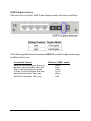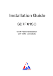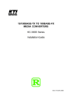
1
Installation Guide
10/100 Fast Ethernet Switch
with 100FX Connectivity
KS-105F Series
DOC.060302-KS105F
-1-
(C) 2005 KTI Networks Inc. All rights reserved. No part of this documentation may be reproduced in any form or by any means or used to make
any directive work (such as translation or transformation) without permission from KTI Networks Inc.
KTI Networks Inc. reserves the right to revise this documentation and to
make changes in content from time to time without obligation on the part
of KTI Networks Inc. to provide notification of such revision or change.
For more information, contact:
United States
International
KTI Networks Inc.
P.O. BOX 631008
Houston, Texas 77263-1008
Phone:
Fax:
E-mail:
WWW:
713-2663891
713-2663893
[email protected]
http://www.ktinet.com/
Fax:
E-mail:
WWW:
886-2-26983873
[email protected]
http://www.ktinet.com.tw/
-2-
The information contained in this document is subject to change without
prior notice. Copyright (C) All Rights Reserved.
TRADEMARKS
Ethernet is a registered trademark of Xerox Corp.
FCC NOTICE
This device complies with Class B Part 15 the FCC Rules. Operation is
subject to the following two conditions: (1) This device may not cause
harmful interference, and (2) this device must accept any interference
received including the interference that may cause.
CE NOTICE
Marking by the symbol
indicates compliance of this equipment to
the EMC directive of the European Community. Such marking is indicative that this equipment meets or exceeds the following technical standards:
EMC Class B
EN 50081-1/1992 : EN55022, EN61000-3-2, EN61000-3-3
EN 50082-1/1998 : EN61000-4-2, EN61000-4-3, EN61000-4-4, EN61000-4-5,
EN61000-4-6, EN61000-4-8, EN61000-4-11
-3-
Table of Contents
1. Introduction .................................................................. 5
1.1 Features ........................................................................................... 6
1.2 Specifications .................................................................................. 7
2. Installing the Switch ..................................................... 9
2.1 Unpacking ....................................................................................... 9
2.2 Checking AC Power ......................................................................... 9
2.3 Installing the Switch ...................................................................... 10
3. Making Network Connections .................................. 11
3.1 Switched Ports ............................................................................... 11
3.2 Making UTP Connections ............................................................. 11
3.3 Making Fiber Connection .............................................................. 12
4. LED Indicators ........................................................... 14
4.1 LED Panel ....................................................................................... 14
4.2 Interpretation ................................................................................. 14
-4-
1. Introduction
This 5-port Fast Ethernet switch series provides four 10/100 TP ports and
one 100BASE-FX fiber port, each capable of transmitting or receiving
information simultaneously at full wire speed to control and allocate the
network bandwidth.
The key features of the switch series are:
• Optimized Bandwidth : Combining five 100Mbps-based Fast
Ethernet switched ports, the switch delivers a high network
bandwidth for your Fast Ethernet network
• Easy Migration : With 10BASE-T support on each port, the switch
provides a non-disruptive and smooth migration path from
Ethernet to a Fast Ethernet network.
• Fiber Uplink Support : With 100BASE-FX port, the switch provides
a connectivity to a Fast Ethernet network via fiber cable.
• Easy Installation : With the functions of auto-speed-sensing and
auto-negotiation on each port, the switch supports plug-and-play
installation which eliminates configuration problems.
-5-
1.1 Features
Designed for resolving congestion problems caused by bandwidth-hungry devices and bandwidth-intensive applications as well as a high number of users, the switches not only adhere to the IEEE 802.3 10BASE-T,
802.3u 100BASE-TX and 100BASE-FX standards, but also feature:
•
•
•
•
•
•
•
•
•
•
Four 10/100BASE-TX auto-negotiation switched ports and one
100BASE-FX port for flexible connections to desktop PCs, servers
and Fast Ethernet devices.
The 10/100BASE-TX switched ports support:
- auto-negotiation with auto-negotiation devices
- full-duplex or half-duplex operation
- automatic MDI/MDI-X configuration
For the 100BASE-FX fiber port, the switch series support variety of
fiber connectors for different application needs. The fiber connectors include ST, SC, MT-RJ, and VF-45 types for multimode and
single mode fiber cables.
Supports duplex mode selector for the 100BASE-FX fiber port.
Self learning for active MAC addresses and address aging
Store and forward switching to ensure only good packets are forwarded
Forwarding and filtering at full wire speed
Supports IEEE 802.3x flow control for full-duplex operation
Supports back-pressure flow control for half-duplex operation
Comprehensive LED indicators provide quick, easy to read port
and switch information
-6-
1.2 Specifications
10/100 Ports
IEEE 802.3 10BASE-T, IEEE 802.3u 100BASE-TX std.
Shielded RJ-45 jacks with Auto MDI-X detection
Auto-negotiation capable
Speed for 10Mbps or 100Mbps
Full-duplex or half-duplex mode support
100FX Port
IEEE 802.3u 100BASE-FX compliant
Fixed 100Mbps operation
Duplex mode selector - full duplex or half duplex
Flow control
IEEE 802.3x pause packet for full duplex operation
Back-pressure for half duplex operation
Cables
10BASE-T Cat. 3, 4, 5 or higher (100 meters max.)
100BASE-TX Cat. 5, 5e or higher (100 meters max.)
100BASE-FX multimode or single mode fiber cable
LED indicators Power status
Per port : Speed, Link, Activity, Duplex, Collision status
Forwarding rate 14,880 pps for Ethernet (10M)
148,800 pps for Fast Ethernet (100M)
Filtering address Multicast/Broadcast/Unicast address
MAC address
1K entries
Aging time
300 seconds
Environment
Temperature -5oC to 40oC
Relative humidity 10% to 90% non-condensing
Dimensions
144 mm x 104.5 mm x 26 mm (WxDxH)
5.67 x 4.11 x 1.02 inch
DC IN Jack
Rating +7.5V/1A, D6.3mm
DC IN voltage
Operating +6.0V ~ +12.6VDC (Device DC Input)
Consumption
DC input power consumption 3.9W @+7.5V
-7-
D2.0mm
100FX Port Fiber Specifications
Duplex Series
Model
KS-105F-T
KS-105F-C
KS-105F-JM
KS-105F-VM
KS-105F-SA2
KS-105F-SL2
KS-105F-SL3
KS-105F-SL4
KS-105F-SL6
KS-105F-SL7
KS-105F-SL9
KS-105F-SL10
KS-105F-SL12
Fiber Wavelength
ST
MMF 1310nm
SC
MMF 1310nm
MT-RJ MMF 1310nm
VF-45 MMF 1310nm
SC
SMF 1310nm
SC
SMF 1310nm
SC
SMF 1310nm
SC
SMF 1310nm
SC
SMF 1310nm
SC
SMF 1310nm
SC
SMF 1310nm
SC
SMF 1550nm
SC
SMF 1550nm
Tx Power
-19 ~ -14dBm
-19 ~ -14dBm
-19 ~ -14dBm
-20 ~ -14dBm
-15 ~ -8dBm
-15 ~ -8dBm
-15 ~ -8dBm
-5 ~ 0dBm
-5 ~ 0dBm
-3 ~ +3dBm
0 ~ +5dBm
-3 ~ +3dBm
0 ~ +5dBm
Sens. Ref.Distance
-31dBm
2km
-31dBm
2km
-31dBm
2km
-31dBm
2km
-31dBm
20km
-32dBm
20km
-34dBm
30km
-34dBm
40km
-35dBm
60km
-37dBm
70km
-37dBm
90km
-37dBm
100km
-37dBm
120km
Ref. Distance : reference distance when operating on full duplex mode
MMF : Multimode fiber - 62.5/125µm, 50/125µm
SMF : Single Mode fiber - 9/125µm
Single Fiber Bi-Di WDM Series
Model
Fiber Wavelength
KS-105F-W3515 SC SMF Tx 1310nm
Rx 1550nm
KS-105F-W5315 SC SMF Tx 1550nm
Rx 1310nm
KS-105F-W3540 SC SMF Tx 1310nm
Rx 1550nm
KS-105F-W5340 SC SMF Tx 1550nm
Rx 1310nm
Tx Power
-14 ~ -8dBm
Sens. Ref.Distance
-31dBm
15-20km
-14 ~ -8dBm
-31dBm
15-20km
-8 ~ 0dBm
-34dBm
40km
-8 ~ 0dBm
-34dBm
40km
Single Mode CWDM Series
Model
KS-105F-CxxW40
KS-105F-CxxW80
Fiber Wavelength
Tx Power Sens. Ref.Distance
SC SMF Tx 1xx0nm
-5 ~ 0dBm -35dBm
40km
Rx 1100-1650nm
SC SMF Tx 1xx0nm
0 ~ +5dBm -37dBm
80km
Rx 1100-1650nm
Tx 1xx0nm : 1470, 1490, 1510, 1530, 1550, 1570, 1590, 1610nm
-8-
2. Installing the Switch
2.1 Unpacking
Check to see that you have everything before you start the installation.
• Installation guide
•
The switch unit
•
One AC power adapter for the unit
2.2 Checking AC Power
Before you begin the installation, check the AC voltage of your area. The
AC power adapter which is used to supply the DC power for the unit should
have the AC voltage matching the commercial power voltage in your area.
The specifications of the AC power adapter are:
•
•
AC input power:
DC output power:
•
DC plug type:
AC power voltage of your area
+7.5VDC 1A min.
-9-
The DC power jack for the AC power adapter is located on the rear of the
switch as shown below:
2.3 Installing the Switch
1. Install the switch with the AC power adapter provided.
2. Connect the power adapter cable to the switch before connecting
the adapter to the AC outlet.
-10-
3. Making Network Connections
3.1 Switched Ports
The following figure shows the locations of the switched ports:
3.2 Making UTP Connections
10/100 TP Port Configuration
All 10/100 TP ports support configuration as follows:
Auto-negotiation capable
Highest capability : 100M Full duplex
Speed : auto-sensing for 100Mbps or 10Mbps
Duplex : Full duplex, Half duplex
Auto MDI-X function
The following table lists the configuration used for the 10/100 port when
it connects to different devices:
Connected Device
10BASE-T hub port
100BASE-TX hub port
Auto-negotiation port
Non-auto*1 half-duplex port
Non-auto full-duplex port
Configuration Used
10Mbps, half-duplex
100Mbps, half-duplex
Determined via auto-negotiation process
auto-speed-sensing *2, half-duplex
Not supported
*1 Non-auto : non-auto-negotiation
*2 speed is determined by auto-sensing function
-11-
Cables
Depending on the connection speed, use the proper UTP cables:
Speed
100M
10M
Cables used
Distance
Cat. 5, 5e, or higher grade
100 meters
Cat. 3, 4, 5, 5e, or higher grade 100 meters
Auto-MDI-X Function
An Auto-MDI-X function will automatically detect if a crossover is required and make the swap of Tx pair and Rx pair internally. With this
function, straight-through cable can be used for any connection. MDI to
MDI-X connection rule is not necessary anymore. In the switches, all TP
ports are equipped with this function. You can use just straight-through
type of cables for all your connections.
3.3 Making Fiber Connection
For different fiber connections, several alternative models can be
selected for different fiber connections. Refer to Section 1.2 for the
model selection. The following figure illustrates a connection example
between two SC fiber ports:
-12-
100FX Duplex Selector
This selector is used for 100FX port duplex mode selection as follows:
The following table lists the maximum MM fiber cable length connecting
to different devices:
Connected Device
Network card half-duplex fiber port
Network card full-duplex fiber port
Class I hub half-duplex fiber port
2 Class II hub half-duplex fiber port
Switched half-duplex fiber port
Switched half-duplex fiber port
-13-
Distance (MMF cable)
400 m
2 km
160 m
112 m
400 m
2 km
4. LED Indicators
4.1 LED Panel
The switch provides comprehensive LED indicators for diagnosing and
monitoring the operation of the switch as illustrated below:
4.2 Interpretation
LED Functions
POWER LED :
indicates the power status of the switch.
LNK/SPD/ACT LED : indicates the link status, connection speed
status, and traffic status of the switched port
DUP/COL LED :
indicates the duplex status and collision status
of the switched port
LED States and Indications
LED
POWER
POWER
State & Color
Off -------On Green
LNK/SPD/ACT
LNK/SPD/ACT
LNK/SPD/ACT
LNK/SPD/ACT
LNK/SPD/ACT
On
On
Blink
Blink
Off
Green
Amber
Green
Amber
--------
DUP/COL
DUP/COL
DUP/COL
On Green
Off -------Blink Green
Indication
No power is supplied to the switch.
Power is being supplied to the switch.
Speed 100M, link up
Speed 10M, link up
Speed 100M, link up, Tx/Rx activities
Speed 10M, link up, Tx/Rx activities
Link down
Full duplex mode
Half duplex mode, no collision
Half duplex mode, collisions
-14-