1
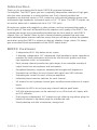
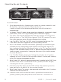
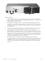
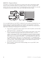
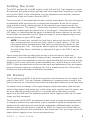
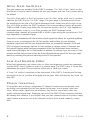
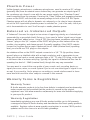
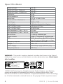
DMP3
Dual mic preamp / direct box
User Guide
Introduction
Thank you for purchasing the M-Audio DMP3 Microphone/Instrument
Pre-Amplifier. The DMP3 gives you two completely independent channels of high gain,
ultra low noise pre-amps in a sturdy desktop unit. Each channel provides low
impedance microphone inputs on XLR connectors with optional phantom power, plus
an alternate high impedance instrument input on 1/4" TS jacks. The DMP3 outputs can
be used as balanced or unbalanced via its 1/4” TRS jacks.
Microphones, guitars with magnetic or piezo pickups, and any instrument that needs a
boost in gain to "line level" will benefit from the superior sonic quality of the DMP3. Two
separate gain ranges are conveniently selectable from the front panel for each DMP3
channel. Low cut "rumble" filters for each channel eliminate unwanted low-end noise,
while individual phase inversion switches ensure that you will always achieve the greatest
result when using the DMP3 in a stereo or dual mic situation. Large, classic VU meters
give an excellent visual representation of the DMP3 output levels.
DMP3 Features
•
2 independent XLR, fully balanced mic inputs.
•
2 alternate, independent 1/4” unbalanced, high impedance inputs, impedance
matched for ideal performance with electric and acoustic guitars and other
high impedance mics or instruments.
•
Each preamp channel provides two gain ranges to accomodate a variety of
output levels from microphones and instruments.
•
Exceptional frequency response, extremely flat throughout all frequencies.
•
Separate low-cut filters for each channel with switch and LED indicator.
•
Separate gain controls for each of the pre-amplifiers.
•
Individual phase inversion switches for each channel.
•
VU meters for each preamp channel gives excellent visual reference of output
levels.
•
Individual clip LEDs for each pre-amp channel indicate peak levels.
•
XLR 48v phantom power can be switched on or off for both mic inputs, with
an LED indicator.
•
Dual-purpose independent 1/4” outputs accept either tip-ring-sleeve plugs for
balanced outputs or tip-sleeve plugs for unbalanced outs.
•
Sturdy desktop unit with a handsome, vintage look.
DMP3 | User Guide
1
Front & Rear Panels
2
5
3
5
3
6
4
6
4
7
8
9
10
1
Front Panel
1.
Gain Adjustment Knobs: Separate gain controls for pre-amp channels A and
B adjust the output volume levels independently. Full
5
counter-clockwise is the minimum gain position, while full clockwise
is
maximum gain.
2.
VU Meters: These VU meters show output level, calibrated to correspond to digital
3
peak meters, where 0 VU is approximately 3dB to 6dB below clipping.
1
3.
Clip LEDs: The Clip LED will light when that input signal is too strong and is
about to distort, or “clip” (4dB below clipping). If this LED remains lit for more
than a few moments, reduce the gain adjustment knob setting.
4.
Low Cut LEDs: The "Low Cut" LED, when lit, indicates that the Low Cut
Filter switch has been engaged for the corresponding channel.
5.
Hi/Lo Gain Switch: This switch will set the “gain range” (or, amount of gain
possible) for the corresponding input channel. Once the gain range is set,
gain is adjusted via the Gain Adjustment Knobs. In the “Out’ position, the gain
range is 32dB to 66dB (Hi gain). In the ‘In’ position, the gain range is 6dB to
36dB (Lo gain). See sections, “Setting the Gain” and “Hi/Lo Gain Switches”
for more information.
6.
Low Cut Filter Switch: Pressing and locking this switch to the ‘In’ position
engages the Low-Cut filter for the associated channel. Pressing and releasing
to the ‘Out’ position disengages the filter.
7.
Main Power LED: When the proper power supply is applied to the DMP3 and
the Main Power switch is switched to the ‘On’ position, this LED will light,
indicating that the unit is powered up.
8.
Phantom Power LED: When lit, this LED indicates that phantom power has
been switched on for both of the mic pre-amp channels.
9.
Main Power Switch: This switch, when pressed and locked to the ‘In’ position,
switches the DMP3 power on.
2
4
10. Phantom Power Switch: When this button is pressed and locked to the ‘In’
position, phantom power (48v) will be sent to both XLR In 1 and XLR In 2.
2
DMP3 | User Guide
5
3
1
2
4
Rear Panel
1.
9vAC Power Supply Jack: This power jack accepts a 9v AC 1 Amp 2.5mm
power supply. This power supply is included with your DMP3, and ONLY the
proper supply should be used.
2.
Output Jacks A and B: These 1/4” TRS jacks are the main outputs for the
pre-amps. Using a TRS (tip-ring-sleeve) 1/4” plug, the DMP3 will provide a
balanced line-level output. Using a TS (tip-sleeve) 1/4” plug, the outputs will
be unbalanced.
3.
Phase Inversion Switches: Each switch will invert the phase of the signal for
the selected channel 180 degrees (see section, "Phase Inversion").
4.
High Impedance Instrument Inputs A and B: These high impedance (100k
Ohm) inputs are optimized for guitars or high impedance microphones. These
jacks are 1/4” TRS, and will accept either 1/4” TRS or TS plugs (balanced or
unbalanced, respectively). When an instrument is plugged into this jack, the
corresponding channel’s XLR input is disabled.
5.
Microphone Inputs A and B: These are the balanced, low impedance
microphone inputs to the pre-amp channels. NOTE: When phantom power is
engaged, power is sent to the ground wire on BOTH of these channels. An
XLR jack is disabled when an instrument is plugged into the corresponding
1/4” jack .
DMP3 | User Guide
3
3
1
DMP3 Operation
A preamp is a necessary
component of any signal chain, when
a microphone, guitar
2
4
pickup or other instrument needs an increase in gain to “line level.” The DMP3 will
perform that role in your signal chain. The drawing below shows the DMP3 in use with
a computer sound card, which in this case is the Delta 66 from M-Audio.
It is conceivable that once the DMP3 is attached to your system and powered up, you
will be plugging and unplugging different microphones and instruments. Follow this
simple procedure, making sure that the gain controls on the DMP3 are at their lowest
levels when attaching or changing mics or instruments.
4
1.
Plug in the 9v "wall wart" power supply into the wall receptacle, and the other
end into your DMP3 9v power jack.
2.
Make the necessary connections from the outputs of the DMP3 to the inputs
of your computer sound card, mixer (use the line level inputs), or sound
system’s power amp. NOTE: If your target device accepts a balanced signal
either on a 1/4” TRS or XLR jack, use a TRS plug (tip-ring-sleeve, typically a
stereo plug) on the outputs of the DMP3. If your target device accepts only
an unbalanced line in, then use a ‘TS’ plug (tip-sleeve, i.e. a standard guitar
cable). Check the documentation of your sound card or other receiving device
if you are unsure. When possible, always use the balanced outputs as this
will provide a quieter and hotter signal.
3.
With all volume controls at their lowest settings, turn on your DMP3, then
your sound system.
DMP3 | User Guide
Setting the Gain
The DMP3 provides up to 66dB of gain on the XLR and 1/4” high impedance inputs.
Microphones and guitar pickups typically emit a low signal level, requiring a "pre-amp"
such as the DMP3. Other instruments, such as keyboard sound modules, may also
benefit from a little bit of punch from the DMP3.
Plug in your mic or instrument with the gain controls turned down, then turn the gain up
incrementally while testing the mic or playing the instrument. When the VU meters
show activity at a fairly consistent level, you’ve reached a good signal level for the
DMP3 (see section, “VU meters”). Some users may wish to experiment a little further
to find what audibly might be referred to as a "sweet spot." Note that when the "clip"
LED lights, it is indicating that the signal is at least 4dB below clipping. Let your ears
be the judge, but when the clip LED lights and stays lit, you are approaching or have
reached distortion in your DMP3 signal.
NOTE: You must also consider the level that is being sent from the DMP3 to
your recording device, sound card input, mixer or sound system. Check the
input meters at the receiving device and make sure that they are neither too low
nor clipping (too ‘hot’). You may be able to adjust the input level or operating
line level of this device, otherwise an adjustment in gain on the DMP3 may be
necessary.
Sound cards and other recording devices may or may not have an input level
adjustment. If your recording device (tape recorder, computer & sound card, etc.) does
not provide input level adjustments, then the signal level that you use to record will rely
totally on your source (voice/mic, guitar/instrument, etc.), and the level you set on the
DMP3. If your recording device does provide input level adjustments, then we suggest
using a unity gain setting as a starting point. This is usually around the 2:00 position,
though your user guide may provide more information.
VU Meters
The VU meters on the DMP3 are there to provide a visual reference to the signal at the
output of the DMP3. They are, however, calibrated to correspond more closely to the
level you will see on a recording device that has digital peak meters to show input level.
VU meters show an average of the signal voltages, while peak meters show the true
peaks in that signal. Peak meters are, in that sense, more sensitive than VU meters, and
are more affected by timbre and pitch. It is possible that a peak meter could be
approching the 0dB level (the maximum possible before clipping), while the VU meter
shows very little movement.
The VU meters on the DMP3 are adjusted so that a more accurate visual representation
is created in relation to the peak meters in your computer or digital recording device. As
mentioned, this relationship will vary between instruments of different timbre and pitch.
Because of that, you may want to compare the DMP3 VU levels to the inputs levels on
your recording device for each performance, and decide how “hot” you can go on the VU
meters before clipping occurs on your recording device.
DMP3 | User Guide
5
Hi/Lo Gain Switches
Two gain ranges are provided for the DMP3 preamps. The “Hi/Lo Gain” switch on the
front panel is used to select between the two gain ranges, with the ‘Out’ position being
the default.
The Hi/Lo Gain switch in the Out position is the “Hi Gain” range, while the ‘In’ position
switches the DMP3 to the “Lo Gain” range. The gain range is considered to be from
the beginning to the end of the Gain Adjustment Knob’s travel from left to right. In the
Out, or Hi Gain position, the DMP3 preamp of the corresponding channel will provide
32dB to 66dB of gain using either the microphone inputs or the 1/4” high impedance
instrument inputs. In the In, or Lo Gain position, the DMP3 preamp (of the
corresponding channel) will provide 6dB to 40dB of gain using the microphone or 1/4”
high impedance instrument inputs.
Some mics or instruments will have a hotter output signal than others. As a general guideline,
if you use a mic or instrument in the Hi Gain position and find that you can achieve a
desirable output level with the Gain Adjustment Knob set somewhere between 10:00 and
2:00 (or higher if necessary), then the Hi Gain position is a proper choice. If, however, you
find yourself clipping while hardly any movement of the Gain Adjustment Knob has been
made, then switching to the Lo Gain position is advised. Conversely, if you are in the Lo Gain
position and find that you have to turn the Gain Adjustment Knob past 2:00, then you might
want to try lowering the gain and switching to the Hi Gain position.
Low-Cut Rumble Filter
When foot movements, mic stand noise, or other low frequency sounds are unwanted,
use the DMP3 Low-Cut filter to reduce or remove them. The DMP3 uses a 3-pole filter,
attenuating the signal 75Hz and below at the rate of 18dB per octave.
A “Low Cut” switch is provided on the front panel of the DMP3. Pressing and locking
this switch to the ‘In’ position will engage the low pass filter, indicated by the lit low cut
filter LED.
Phase Inversion
It is possible, with a stereo configuration (2-channel) or when two microphones are
recording one instrument, for the two signals to become "out of phase" with each
other. When similar signals are out of phase, they tend to cancel each other out,
greatly reducing signal level. Engaging just one of the DMP3 Phase Inversion switches
will remedy this situation. If you suspect that your two channels are out of phase, simply
switch phase reverse for one of the channels and see if the sound suddenly ‘comes
alive.’
6
DMP3 | User Guide
Phantom Power
Unlike dynamic microphones, condenser microphones need to receive a DC voltage
(generally 48v) from an external source before they can generate an output signal. If
the condenser mic doesn’t come with its own power supply, then "Phantom Power"
must be applied from the pre-amp. Pressing the "Phan" button and engaging phantom
power on the DMP3 will send the necessary voltage to both of the XLR Mic Inputs.
Phantom power will not affect a dynamic mic adversely, so its okay to have a dynamic
mic at the XLR input while phantom power is switched on. Just to be safe, check you
mic’s documentation to see if it will accept or needs phantom power.
Balanced vs. Unbalanced Outputs
A "balanced" line runs the signal on two wires of opposing polarity, as a ‘twisted pair’
surrounded by a grounded shield. Doing so, it can send a ‘hotter’ signal over a longer
distance with less added noise. Using a TRS (tip-ring-sleeve, sometimes referred to as
“stereo”) plug on the 1/4” outputs of the DMP3 will give you this balanced line—tip
positive, ring negative, and sleeve ground. Generally speaking, if the DMP3 outputs
connect to a system that accepts a balanced line at +4dB (nominal level) operating
level, you should use TRS plugs on the outputs.
An unbalanced line on the DMP3 outputs connects to a 1/4” TS (tip positive, sleeve
ground) plug on a shielded cable with a single conductor, and is appropriate to use
when your sound card or sound system accepts a 1/4” TS plug, RCA plug, or the right
or left mono side of a stereo mini-plug. Typically, the signal on unbalanced lines has an
operating line level of –10dB (nominal level), though this may vary somewhat.
You may want to consult the user guide of your sound card, recording device or
signal processor, mixer, or sound system if you’re not sure what type of signal it can
accept. If you need to, find a primer on recording or sound reinforcement to learn
more about this and the other subjects covered in this manual.
Warranty Terms & Registration
Warranty Terms
M-Audio warrants products to be free from defects in materials and workmanship,
under normal use and provided that the product is owned by the original,
registered user. Visit www.m-audio.com/warranty for terms and limitations applying
to your specific product.
Warranty Registration
Immediately registering your new M-Audio product entitles you to full warranty
coverage and helps M-Audio develop and manufacture the finest quality products
available. Register online at www.m-audio.com/register to receive FREE product
updates and for the chance to win M-Audio giveaways.
DMP3 | User Guide
7
Specifications
Maximum Input:
+10 dBv
Maximum Output - Balanced:
+22 dBv
Maximum Output - Unbalanced:
+16 dBv
Headroom:
22 dB
Meter headroom:
12 dB
Meter level:
0 VU @ +12dBV, 1KHz
Maximum Gain - Mic/Instr. In:
66 dB
Gain Range:
13dB to 73dB
Clip Indicator:
3 dB below threshold of clipping
Low Cut Filter Cutoff:
3 dB down @ 72 Hz
Low Cut Filter Slope:
18 dB/Octave
Input Impedance (1 kHz) - Mic In:
3 kOhms
Input Impedance (1 kHz) - Instr. In:
100 kOhms
Noise Factor:
< 1.5dB @ maximum gain
Signal to noise:
115dB “A” weighted @ minimum gain
THD:
0.02% @ minimum gain (THD is below
noise floor at most higher gain settings)
Frequency response:
20Hz to 80KHz; +0; -1 dB
Weight:
Under l lb.
Power Supply:
9vAC 1Amp supply w/2.5mm plug.
Output Impedance:
500 Ohms.
WARNING: This product contains chemicals, including lead, known to the State of
California to cause cancer, and birth defects or other reproductive harm. Wash hands
after handling.
DMP3
Tested to comply with
FCC standards
FOR HOME OR STUDIO USE
© 2008 Avid Technology, Inc. All rights reserved. Product features, specifications,
system requirements and availability are subject to change without notice. Avid,
M-Audio and DMP3 are either trademarks or registered trademarks of Avid Technology,
Inc. All other trademarks contained herein are the property of their respective owners.
8
DMP3 | User Guide
M-Audio USA
M-Audio Germany
5795 Martin Rd., Irwindale, CA 91706
Kuhallmand 34, D-74613 Ohringen, Germany
Technical Support
Technical Support
web . . . . . . . . . . . .
tel (pro products) . . . .
tel (consumer products) .
fax (shipping). . . . . . .
www.m-audio.com/tech
. . . . (626) 633-9055
. . . . (626) 633-9066
. . . . (626) 633-9032
Sales
e-mail . . . . . . . . . . . . . [email protected]
tel . . . . . . . . . . . . . . . . 1(866) 657-6434
fax . . . . . . . . . . . . . . . . (626) 633-9070
Web .
Sales
e-mail . . . . . . . . . . . . . . . . [email protected]
tel . . . . . . . . . . . . . . .+49 (0)7941 98 7000
fax . . . . . . . . . . . . . +49 (0)7941 98 70070
Web .
. . . . . . . . . . . . . . . . www.m-audio.de
. . . . . . . . . . . . . . www.m-audio.com
M-Audio U.K.
Floor 6, Gresham House, 53 Clarendon Road,
Watford WD17 1LA, United Kingdom
M-Audio Canada
1400 St-Jean Baptiste Ave. #150, Quebec City,
Quebec G2E 5B7, Canada
Technical Support
Technical Support
e-mail . . . . . . . . . . . [email protected]
tel (Mac and PC support) +44 (0)1753 658630
Sales
e-mail . . . . . . . . . . [email protected]
tel . . . . . . . . . . . . . . . . . . (418) 872-0444
fax . . . . . . . . . . . . . . . . . (418) 872-0034
Sales
tel . . . . . . . . . . . . . +44 (0)1923 204010
tel . . . . . . . . . . . . . +44 (0)1923 204039
Web .
email . . . . . . . . . . . . . [email protected]
tel . . . . . . . . . . . . . +49 (0)7941 - 9870030
tel . . . . . . . . . . . . . +49 (0)7941 - 98 70070
. . . . . . . . . . . . . www.maudio.co.uk
e-mail . . . . . . . . . . . [email protected]
tel . . . . . . . . . . . . . . . . . . (866) 872-0444
fax . . . . . . . . . . . . . . . . . (418) 872-0034
Web .
. . . . . . . . . . . . . . . . www.m-audio.ca
Benelux
M-Audio Japan
Technical Support
Belgium tel . . . . . . . . . . . +32 22 54 88 93
Holland tel . . . . . . . . . . . +31 35 625 0097
M-Audio France
Floor 6, Gresham House, 53 Clarendon Road,
Watford WD17 1LA, United Kingdom
Renseignements Commerciaux
エムオーディオ/アビッドテクノロジー株式会社
〒107-0052 東京都港区赤坂 2-11-7 ATT新館ビル4F
Avid Technology K.K. | M-Audio
4F ATT Bldg. 2-11-7 Akasaka, Minato-ku
Tokyo 107-0052 Japan
製品をお持ちのお客様|Customer Support
& Technical Support
online . . . . . . . . .http://www.m-audio.jp/support
tel . . . . . . . . . . . . . . . . . 0 810 001 105
email . . . . . . . . . . . . . . . [email protected]
Assistance Technique
PC . . . . .
Mac. . . . .
e-mail (PC) .
email (Mac).
fax . . . . .
Web .
.
.
.
.
.
.
.
.
.
.
.
.
.
.
.
.
.
.
.
.
.
.
.
.
.
.
.
.
.
.
.
.
.
.
.
. . . . 0 820 000 731
. . . . 0 820 391 191
. . [email protected]
. . . . [email protected]
.+33 (0)1 72 72 90 52
. . . . . . . . . . . . . .www.m-audio.com
tel . . . . . . . . . . . . . . . . . . . . 03-3505-4034
製品をお持ちでないお客様|Pre Sales
e-mail . . . . . . . . . . . . . . . . [email protected]
tel . . . . . . . . . . . . . . . . . . . . 03-3505-7963
fax . . . . . . . . . . . . . . . . . . . 03-3505-3417
Web .
. . . . . . . . . . . . . . . . . .www.m-audio.jp
Web .
. . . . . . . . . . . . . . . . . .www.m-audio.jp
080516_DMP3_UG_EN01
PART NUMBER