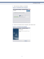
1
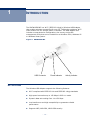
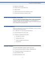
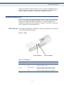
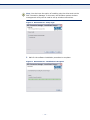
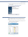
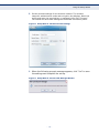
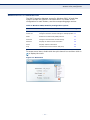
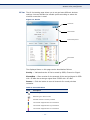
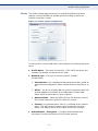
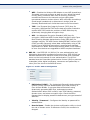
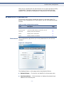
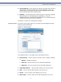
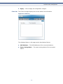
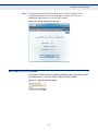
USER GUIDE
EZ ConnectTM N
150 Mbps N Wireless USB Adapter
SMCWUSBS-N3
150 Mbps N Wireless USB Adapter
User Guide
20 Mason
Irvine, CA 92618
Phone: (949) 679-8000
September 2009
149100000053W
E092009-AP-R01
Information furnished by SMC Networks, Inc. (SMC) is believed to be accurate and reliable.
However, no responsibility is assumed by SMC for its use, nor for any infringements of patents or
other rights of third parties which may result from its use. No license is granted by implication or
otherwise under any patent or patent rights of SMC. SMC reserves the right to change specifications
at any time without notice.
Copyright © 2009 by
SMC Networks, Inc.
20 Mason
Irvine, CA 92618
All rights reserved
Trademarks:
SMC is a registered trademark; and EZ Switch, TigerStack, TigerSwitch, and TigerAccess are
trademarks of SMC Networks, Inc. Other product and company names are trademarks or registered
trademarks of their respective holders.
WARRANTY AND PRODUCT REGISTRATION
To register SMC products and to review the detailed warranty statement,
please refer to the Support Section of the SMC Website at http://
www.smc.com.
– 4 –
COMPLIANCES
FEDERAL COMMUNICATION COMMISSION INTERFERENCE STATEMENT
This equipment has been tested and found to comply with the limits for a
Class B digital device, pursuant to Part 15 of the FCC Rules. These limits
are designed to provide reasonable protection against harmful interference
in a residential installation. This equipment generates, uses and can
radiate radio frequency energy and, if not installed and used in accordance
with the instructions, may cause harmful interference to radio
communications. However, there is no guarantee that interference will not
occur in a particular installation. If this equipment does cause harmful
interference to radio or television reception, which can be determined by
turning the equipment off and on, the user is encouraged to try to correct
the interference by one of the following measures:
◆
Reorient or relocate the receiving antenna
◆
Increase the separation between the equipment and receiver
◆
Connect the equipment into an outlet on a circuit different from that to
which the receiver is connected
◆
Consult the dealer or an experienced radio/TV technician for help
This device complies with Part 15 of the FCC Rules. Operation is subject to
the following two conditions: (1) This device may not cause harmful
interference, and (2) this device must accept any interference received,
including interference that may cause undesired operation.
FCC Caution: Any changes or modifications not expressly approved by the
party responsible for compliance could void the user's authority to operate
this equipment.
IMPORTANT NOTE:
FCC RADIATION EXPOSURE STATEMENT
This equipment complies with FCC radiation exposure limits set forth for an
uncontrolled environment. End users must follow the specific operating
instructions for satisfying RF exposure compliance. To maintain compliance
with FCC RF exposure compliance requirements, please follow operation
instruction as documented in this manual.
This transmitter must not be co-located or operating in conjunction with
any other antenna or transmitter.
IEEE 802.11b, 802.11g or 802.11n operation of this product in the U.S.A.
is firmware-limited to channels 1 through 11.
– 5 –
COMPLIANCES
TAIWAN NCC 低功率輻射規定
根據國家通信傳播委員會低功率電波輻射性電機管理辦法之規定,應包含下列警語:
第十二條 經型式認證合格之低功率射頻電機,非經許可,公司、商號或使用者均不得
擅自變更頻率、加大功率或變更原設計之特性及功能。
第十四條 低功率射頻電機之使用不得影響飛航安全及干擾合法通信;經發現有干擾現
象時,應立即停用,並改善至無干擾時方得繼續使用。前項合法通信,指依電信法規
定作業之無線電通信。低功率射頻電機須忍受合法通信或工業、科學及醫療用電波輻
射性電機設備之干擾。
EC CONFORMANCE DECLARATION
Marking by the above symbol indicates compliance with the Essential
Requirements of the R&TTE Directive of the European Union (1999/5/EC).
This equipment meets the following conformance standards:
◆
EN 60950-1: 2006 (IEC 60950-1) - Product Safety
◆
EN 300 328 V1.7.1 (2006-10) - Technical requirements for 2.4 GHz
radio equipment
◆
EN 301 489-1 V1.8.1 (2008-04) and EN 301 489-17 V1.3.2 (2008-04) EMC requirements for radio equipment
◆
EN 62311 (2008) -Assessment of electronic and electrical equipment
related to human exposure restrictions for electromagnetic fields
(0 Hz – 300 GHz)
This device is intended for use in the following European Community and
EFTA countries:
◆
◆
◆
◆
◆
◆
Austria
Denmark
Greece
Latvia
Norway
Slovenia
◆
◆
◆
◆
◆
◆
Belgium
Estonia
Hungary
Lithuania
Poland
Spain
◆
◆
◆
◆
◆
◆
◆
Finland
◆
Iceland
◆
Luxembourg ◆
Portugal
◆
Sweden
◆
Bulgaria
◆
France
◆
Ireland
◆
Malta
◆
Romania
◆
Switzerland ◆
Cyprus
Czech Republic
Germany
Italy
Netherlands
Slovakia
United Kingdom
This device is a 2.4 GHz wideband transmission system (transceiver),
intended for use in all EU member states and EFTA countries, except in
France and Italy where restrictive use applies.
◆
In Italy the end-user should apply for a license at the national spectrum
authorities in order to obtain authorization to use the device for setting
up outdoor radio links and/or for supplying public access to
telecommunications and/or network services.
◆
This device may not be used for setting up outdoor radio links in France
and in some areas the RF output power may be limited to 10 mW EIRP
in the frequency range of 2454 – 2483.5 MHz. For detailed information
the end-user should contact the national spectrum authority in France.
– 6 –
COMPLIANCES
Czech
Česky
SMC Networks tímto prohlašuje, že tento Radio LAN device je ve shodě se
základními požadavky a dalšími příslušnými ustanoveními směrnice 1999/5/ES.
Danish
Dansk
Undertegnede SMC Networks erklærer herved, at følgende udstyr Radio LAN
device overholder de væsentlige krav og øvrige relevante krav i direktiv
1999/5/EF.
German
Deutsch
Hiermit erklärt SMC Networks, dass sich dieses Wireless LAN Gerat in
Übereinstimmung mit den grundlegenden Anforderungen und den anderen
relevanten Vorschriften der Richtlinie 1999/5/EG befindet. Die offizielle ECDeclaration of Conformity finden Sie im Internet unter http://www.smc.com
unter der entsprechenden Produktkategorie.
Estonian
Eesti
Käesolevaga kinnitab SMC Networks seadme Radio LAN device vastavust
direktiivi 1999/5/EÜ põhinõuetele ja nimetatud direktiivist tulenevatele teistele
asjakohastele sätetele.
English
Hereby, SMC Networks, declares that this Radio LAN device is in compliance
with the essential requirements and other relevant provisions of Directive 1999/
5/EC. The official EC-Declaration of Conformity can be found under the
corresponding product section on the web http://www.smc.com.
Spanish
Español
Por medio de la presente SMC Networks declara que el Radio LAN device cumple
con los requisitos esenciales y cualesquiera otras disposiciones aplicables o
exigibles de la Directiva 1999/5/CE. The official EC-Declaration of Conformity
can be found under the corresponding product section on the web
http://www.smc.com.
Greek
Ελληνική
ΜΕ ΤΗΝ ΠΑΡΟΥΣΑ SMC Networks ΔΗΛΩΝΕΙ ΟΤΙ radio LAN device
ΣΥΜΜΟΡΦΩΝΕΤΑΙ ΠΡΟΣ ΤΙΣ ΟΥΣΙΩΔΕΙΣ ΑΠΑΙΤΗΣΕΙΣ ΚΑΙ ΤΙΣ ΛΟΙΠΕΣ
ΣΧΕΤΙΚΕΣ ΔΙΑΤΑΞΕΙΣ ΤΗΣ ΟΔΗΓΙΑΣ 1999/5/ΕΚ.
French
Français
Par la présente SMC Networks déclare que l'appareil Radio LAN device est
conforme aux exigences essentielles et aux autres dispositions pertinentes de
la directive 1999/5/CE. La declaration de conformité officielle peut être trouvée
sur notre site internet
http://www.smc.com dans la rubrique Produits.
Italian
Italiano
Con la presente SMC Networks dichiara che questo Radio LAN device è
conforme ai requisiti essenziali ed alle altre disposizioni pertinenti stabilite dalla
direttiva 1999/5/CE.
Latvian
Lativiski
Ar šo SMC Networks deklarē, ka Radio LAN device atbilst Direktīvas 1999/5/EK
būtiskajām prasībām un citiem ar to saistītajiem noteikumiem.
Lithuanian
Lietuvių
Šiuo SMC Networks deklaruoja, kad šis Radio LAN device atitinka esminius
reikalavimus ir kitas 1999/5/EB Direktyvos nuostatas.
Dutch
Hierbij verklaart SMC Networks dat het toestel Radio LAN device in
Nederlands overeenstemming is met de essentiële eisen en de andere relevante bepalingen
van richtlijn 1999/5/EG
Maltese
Malt
Hawnhekk, SMC Networks, jiddikjara li dan Radio LAN device jikkonforma malħtiġijiet essenzjali u ma provvedimenti oħrajn relevanti li hemm fid-Dirrettiva
1999/5/EC.
Hungarian
Magyar
Alulírott, SMC Networks nyilatkozom, hogy a Radio LAN device megfelel a
vonatkozó alapvetõ követelményeknek és az 1999/5/EC irányelv egyéb
elõírásainak.
Polish
Polski
Niniejszym SMC Networks oświadcza, że Radio LAN device jest zgodny z
zasadniczymi wymogami oraz pozostałymi stosownymi postanowieniami
Dyrektywy 1999/5/EC.
Portuguese SMC Networks declara que este Radio LAN device está conforme com os
Português requisitos essenciais e outras disposições da Directiva 1999/5/CE.
Slovak
Slovensky
SMC Networkstýmto vyhlasuje, že Radio LAN device spĺňa základné požiadavky
a všetky príslušné ustanovenia Smernice 1999/5/ES.
Finnish
suomi
Valmistaja SMC Networks vakuuttaa täten että Radio LAN device tyyppinen laite
on direktiivin 1999/5/EY oleellisten vaatimusten ja sitä koskevien direktiivin
muiden ehtojen mukainen.
Swedish
Svenska
Härmed intygar SMC Networks att denna Radio LAN device står I
överensstämmelse med de väsentliga egenskapskrav och övriga relevanta
bestämmelser som framgår av direktiv 1999/5/EG
– 7 –
COMPLIANCES
Icelandic
Hér með lýsir SMC Networks yfir Því að Radio LAN device er í samræmi við
grunnkröfur og aðrar kröfur, sem gerðar eru í tilskipun 1995/5/EC.
Norwegian
SMC Networks erklærer herved at utstyret Radio LAN device er i samsavar
med de grunnleggende krav og øvrige relevante krav i direktiv 1995/5/EF.
– 8 –
ABOUT THIS GUIDE
PURPOSE This guide details the hardware features of the wireless USB adapter,
including its physical and performance-related characteristics, and how to
install the device and use its configuration software.
AUDIENCE This guide is for PC users with a working knowledge of computers. You
should be familiar with Windows operating system concepts.
CONVENTIONS The following conventions are used throughout this guide to show
information:
NOTE: Emphasizes important information or calls your attention to related
features or instructions.
CAUTION: Alerts you to a potential hazard that could cause loss of data, or
damage the system or equipment.
WARNING: Alerts you to a potential hazard that could cause personal injury.
RELATED PUBLICATIONS The following publication gives basic information on how to install and use
the wireless USB adapter.
The SMCWUSBS-N3 Quick Installation Guide
Also, as part of the wireless USB adapter’s software, there is an online
web-based help that describes all configuration related features.
REVISION HISTORY This section summarizes the changes in each revision of this guide.
SEPTEMBER 2009 REVISION
This is the first revision of this guide.
– 9 –
CONTENTS
WARRANTY AND PRODUCT REGISTRATION
4
COMPLIANCES
5
ABOUT THIS GUIDE
9
CONTENTS
10
1 INTRODUCTION
12
Key Features
12
Description of Hardware Capabilities
13
System Requirements
13
Package Contents
13
Hardware Description
14
LED Indicators
14
2 WINDOWS 2000/XP INSTALLATION
Using the Setup Wizard
3 WINDOWS 2000/XP CONFIGURATION
15
17
20
Accessing the SMC Connection Manager
20
Wireless Utility Configuration
21
AP List
22
Profile
23
WMM
26
Advanced
27
Statistics
28
About
29
Help
29
4 NETWORK PLANNING
30
Ad Hoc Wireless LAN
30
Infrastructure Wireless LAN
31
5 AP MODE CONFIGURATION
– 10 –
32
CONTENTS
Switching to AP Mode
32
AP Mode Utility Configuration
33
Configuration
33
Access Control
35
Client List
36
Status
37
About
38
Switching to Station Mode
A TROUBLESHOOTING
38
39
USB Adapter Installation Problems
39
Network Connection Problems
39
Uninstalling the Utility
40
B HARDWARE SPECIFICATIONS
42
GLOSSARY
44
INDEX
48
– 11 –
1
INTRODUCTION
The SMCWUSBS-N3 is a Wi-Fi (IEEE 802.11b/g/n) Wireless USB Adapter
that enables wireless connectivity for your PC. The device provides a Wi-Fi
client solution for PCs using a USB 2.0 interface. The USB adapter also
includes a comprehensive configuration, site survey, and profile
management utility that can be installed on a Windows 2000, Windows XP
or Windows Vista system.
Figure 1: SMCWUSBS-N3
USB Connector
Power Indicator
Activity Indicator
KEY FEATURES
The Wireless USB Adapter supports the following features:
◆
Wi-Fi compliant with IEEE 802.11n and IEEE 802.11b/g standards
◆
High-speed connection up to 150 Mbps in 802.11n mode
◆
Dynamic data rate scaling from 1 to 150 Mbps
◆
Low interference and high susceptibility to guarantee reliable
performance
◆
Supports WEP, WPA-PSK, WPA2-PSK security
– 12 –
CHAPTER 1 | Introduction
Description of Hardware Capabilities
◆
WMM (Wi-Fi Multimedia)
◆
Windows 2000, XP and Vista drivers
◆
WHQL certified
◆
WLAN site survey and profile management utility
◆
Infrastructure and Ad-hoc operating modes
DESCRIPTION OF HARDWARE CAPABILITIES
SMC’s EZ Connect Wireless USB Adapter supports wireless communications
at up to 150 Mbps. This adapter operates in the 2.4 GHz band and is fully
compliant with IEEE 802.11b/g and 802.11n. It can be installed in a
notebook or desktop PC with a USB port. Support is provided for Windows
2000, Windows XP, and Windows Vista.
SYSTEM REQUIREMENTS
Before you install the EZ Connect Wireless USB Adapter, check your system
meets the following requirements:
◆
2.4 GHz 802.11n or 802.11b/g wireless network.
◆
Microsoft Windows 2000, XP or Vista.
◆
A Notebook or desktop computer with:
■
300 MHz CPU or above
■
Available USB 2.0 port
■
20 MB of available hard disk space
■
CD-ROM drive
PACKAGE CONTENTS
The Wireless USB Adapter package includes these items:
◆
EZ Connect N Wireless USB 2.0 Adapter (SMCWUSBS-N3)
◆
EZ Installation Wizard & Documentation CD
◆
Quick Installation Guide
◆
Warranty Information Card
– 13 –
CHAPTER 1 | Introduction
Hardware Description
Inform your dealer if there are any incorrect, missing or damaged items. If
possible, retain the carton, including the original packing materials. Use
them to repack the product in case there is a need to return it.
HARDWARE DESCRIPTION
SMC’s EZ Connect Wireless USB Adapter supports wireless communications
at up to 150 Mbps. This adapter operates in the 2.4 GHz band and is fully
compliant with IEEE 802.11b/g and 802.11n. It can be installed in a
notebook or desktop PC with a USB port. Support is provided for Windows
2000, Windows XP, and Windows Vista.
LED INDICATORS The Wireless USB Adapter includes two status LED indicators, as described
in the following figure and table.
Figure 2: LEDs
Power Indicator
Activity Indicator
Table 1: LED Behavior
LED
Status
Description
Power
On
Indicates the power is on.
Off
Indicates the power is off.
Flashing Green
Indicates the 802.11b/g/n radio is enabled.
Flashing indicates wireless network activity.
Off
Indicates the 802.11b/g/n radio is disabled
Activity
– 14 –
2
WINDOWS 2000/XP INSTALLATION
The CD-ROM that comes with the package contains the USB driver and
software utility for the Wireless USB Adapter. New or updated drivers can
be downloaded from SMC’s web site at http://www.smc.com.
The installation screens are similar for Windows 2000, Windows XP and
Windows Vista. The installation interface for Windows XP is shown in this
user guide.
To install the Wireless USB Adapter's driver and utilities for Windows 2000
and Windows XP, follow these steps:
1. Turn on your PC and wait until the Windows system has completely
started.
2. Load the EZ Installation & Documentation CD that comes with the
package. The install program should start automatically.
3. Click “Install SMC Connection Manager” to start the installation.
Figure 3: EZ Connect CD - Start Screen
4. Choose “Install driver and SMC Connection Manager”, then click Next to
continue the installation. If the install program does not start
automatically, open the folder that displays the CD’s contents and find
the file “Install.exe” in the root directory. Double click the file to start
the install program.
– 15 –
CHAPTER 2 | Windows 2000/XP Installation
NOTE: You also have the option of installing only the driver and not the
SMC Connection Manager. In this case, the Windows system wireless
management utility can be used to set up wireless connections.
Figure 4: EZ Connect CD - Setup Type
5. Wait for the software installation procedure to complete.
Figure 5: EZ Connect CD - Installation in Progress
– 16 –
CHAPTER 2 | Windows 2000/XP Installation
Using the Setup Wizard
6. When the “InstallShield Wizard Complete” window displays, click Finish
to exit the wizard.
Figure 6: EZ Connect CD - Installation Wizard Complete
USING THE SETUP WIZARD
Once the InstallShield Wizard is complete, the Setup Wizard takes you
through configuration procedures for the general settings. Follow these
steps:
1. Select the AP to which you want to connect from the displayed list, then
click “Next” to continue the configuration.
Figure 7: Setup Wizard - Select an AP
– 17 –
CHAPTER 2 | Windows 2000/XP Installation
Using the Setup Wizard
2. Set the wireless settings for the wireless network. The wireless
network's authentication mode and encryption key displays. Name the
profile and enter the required key or password, then click "Connect."
The wizard will save these settings as the default connection profile.
Figure 8: Setup Wizard - Wireless Profile Settings
3. When the following prompt message appears, click “Yes” to save
the settings and complete the set-up.
Figure 9: Setup Wizard - Save Profile Message Window
– 18 –
CHAPTER 2 | Windows 2000/XP Installation
Using the Setup Wizard
When the setup is complete, the current link status is displayed, as shown
in the following figure.
Figure 10: Setup Wizard - Link Status
◆
Network Name — The service set identifier for the access point.
◆
Link Status — The connection status. For more information, please
refer to below table.
Table 2: Link Status Description
Status
Description
Card not found
The USB adapter is not plugged in.
Driver not ready
During first-time installation, the USB adapter utility has
completed installation, but the driver is not yet installed.
Auto Config service is disabled
The Wi-Fi automatic configuration service is disabled and
there is no network connection.
Connecting
The USB adapter is being connected to a network.
Disconnected
The USB adapter is plugged in, but is not connected to a
network.
Link is up
Connected to a network.
Link is down
No Connection.
◆
Signal Strength — The current receive signal strength indication. (The
maximum strength will display with six bars.)
◆
Channel — The current channel in use.
◆
IP Address — The assigned IP address of the USB adapter.
– 19 –
3
WINDOWS 2000/XP CONFIGURATION
ACCESSING THE SMC CONNECTION MANAGER
Once the SMC Connection Manager installation is complete, the
configuration utility can be accessed by selecting the “SMC Connection
Manager” icon from the “SMC” folder.
Figure 11: Accessing EZ Connect N3 Wireless Utility
A quick launch icon will appear in the lower right-hand corner of the task
bar.
Figure 12: EZ Connect N3 Wireless Utility Icon
When the utility icon is displayed, it indicates that the Wireless USB
Adapter driver is installed properly.
Double-click the icon to open the SMC Connection Manager program,
providing quick access to the adapter settings.
The utility screens are similar in Microsoft Windows 2000, XP and Vista.
The interface for Windows XP is described in this user guide.
– 20 –
CHAPTER 3 | Windows 2000/XP Configuration
Wireless Utility Configuration
WIRELESS UTILITY CONFIGURATION
The SMC Connection Manager screen for Windows 2000, XP and Vista
systems include the options in the table below. For details on the
configuration for each feature, see the corresponding page number.
Table 3: Windows 2000/XP Utility Configuration Options
Tools
Description
Page
AP List
Displays available wireless networks
22
Profile List
Configures the basic wireless settings for multiple profiles 23
WMM
Enables Wi-Fi Multimedia (WMM) features
26
Advanced
Configures the advanced wireless settings
27
Statistics
Displays the detail counter information
28
About
Displays software information
29
Help
Launches EZ connect wireless utility help
29
To access menu items, double click the quick launch icon and then click on
to display the menu.
Figure 13: Menu Item
– 21 –
CHAPTER 3 | Windows 2000/XP Configuration
Wireless Utility Configuration
AP LIST The AP List setting page allows you to set and save different wireless
settings. You can activate the suitable profile according to where the
wireless connection is used.
Figure 14: AP List
Close Button
Minimize Button
Expand/Collaspe Button
Rescan Button
The displayed items on this page can be described as follows:
Sort by — Indicate that the AP list is sorted by SSID, Channel or Signal.
Show dBm — Show a value for the strength of the received signal. A SSID
with -55 dBm has a stronger signal than a SSID with –87 dBm.
Rescan — Click the button to scan all channels for nearby wireless
networks.
Table 4: Icon Indications
Icons
Description
Network type is infrastructure mode
Network type is ad-hoc mode
Wireless network is security-enabled
The network supports 802.11b connections
The network supports 802.11g connections
The network supports 802.11n connections
– 22 –
CHAPTER 3 | Windows 2000/XP Configuration
Wireless Utility Configuration
PROFILE The profile settings page allows you to set and save different wireless
settings. You can activate the suitable profile according to where the
wireless connection is used.
Figure 15: Profile - System Configuration
To Add a profile, click the Add button and configure the following displayed
items:
◆
Profile Name – The name of the profile. (0-32 ASCII characters and
symbols are allowed; no spaces can be used)
◆
Network Type – The type of wireless network. (Default:
Infrastructure)
◆
■
Infrastructure – An integrated wireless and wired LAN is called an
Infrastructure configuration. Select Infrastructure to associate to an
AP.
■
Ad hoc – An ad hoc wireless LAN is a group of computers each with
wireless adapters, connected as an independent wireless LAN.
Select Ad hoc to associate to a peer computer.
■
Network Name – Select the SSID (Service Set Identity) name of
the wireless network to which the client will connect.
■
Channel (only available when “Ad hoc” is selected as the network
type) – The radio channel used to communicate with wireless
clients. The channel has to be the same as the peer computer.
Authentication / Encryption — Configure authentication and
encryption to match the security of the wireless network.
– 23 –
CHAPTER 3 | Windows 2000/XP Configuration
Wireless Utility Configuration
Figure 16: Profile - Authentication and Encryption
The displayed items on this page can be described as follows:
◆
◆
Authentication – Select the authentication mode. For an
infrastructure network, six modes are supported by the Wireless USB
Adapter, including Open, Shared, WPA-PSK, WPA2-PSK, WPA and
WPA2. For an ad hoc network, Open and Shared modes are supported.
■
Open – Open-system authentication accepts any client attempting
to connect to the access point without verifying its identity.
■
Shared – The shared-key approach uses Wired Equivalent Privacy
(WEP) to verify client identity by distributing a shared key to clients
before attempting authentication.
■
WPA / WPA-PSK – Wi-Fi Protected Access (WPA) employs a
combination of technologies to provide an enhanced security
solution for wireless networks. The WPA Pre-shared Key (WPA-PSK)
mode for small networks uses a common password phrase that
must be manually distributed to all clients that want to connect to
the network.
■
WPA2 / WPA2-PSK – WPA2 is a further security enhancement
that includes the now ratified IEEE 802.11i wireless security
standard.
Encryption – Configure the encryption. For open and shared
authentication mode, the selection options are None and WEP. For WPA,
WPA2, WPA-PSK and WPA2-PSK authentication mode, the encryption
type supports both TKIP and AES.
■
None – No encryption is used.
– 24 –
CHAPTER 3 | Windows 2000/XP Configuration
Wireless Utility Configuration
◆
■
WEP – Enables the Wireless USB Adapter to use WEP shared keys.
If enabled, you must configure at least one key. Wired Equivalent
Privacy (WEP) provides a basic level of security, preventing
unauthorized access to the network and encrypting data
transmitted between wireless clients. WEP uses static shared keys
(fixed-length hexadecimal or alphanumeric strings) that are
manually distributed to all clients that want to use the network.
■
TKIP – Use Temporal Key Integrity Protocol (TKIP) keys for
encryption. WPA specifies TKIP as the data encryption method to
replace WEP. TKIP avoids the problems of WEP static keys by
dynamically changing data encryption keys.
■
AES – Use Advanced Encryption Standard (AES) keys for
encryption. WPA2 uses AES Counter-Mode encryption with Cipher
Block Chaining Message Authentication Code (CBC-MAC) for
message integrity. The AES Counter-Mode/CBCMAC Protocol (AESCCMP) provides extremely robust data confidentiality using a 128bit key. Use of AES-CCMP encryption is specified as a standard
requirement for WPA2. Before implementing WPA2 in the network,
be sure client devices are upgraded to WPA2-compliant hardware.
802.1X — Use IEEE 802.1X (802.1X) for user authentication and
distributing dynamically generated encryption keys. IEEE 802.1X is a
standard framework for network access control that uses a RADIUS
server on the local network for user authentication. The 802.1X
standard uses the Extensible Authentication Protocol (EAP) to pass user
credentials (either digital certificates, usernames and passwords, or
other) from the client to the RADIUS server.
Figure 17: Profile - 802.1X Configuration
■
EAP Method (LEAP) – The Lightweight Extensible Authentication
Protocol (LEAP) is an EAP authentication type used primarily in
Cisco Aironet WLANs. It encrypts data transmissions using
dynamically generated WEP keys, and supports mutual
authentication.When LEAP is select, input LEAP identity, password,
domain name, and select encryption type. Check the Show
Password box to display password characters as you type instead of
asterisks.
■
Identity / Password – Configures the identity an password for
authentication.
■
Domain Name – Enable the wireless configuration utility to check
the end of domain name. If defects are found, the connection is
dropped.
– 25 –
CHAPTER 3 | Windows 2000/XP Configuration
Wireless Utility Configuration
WMM Wi-Fi Multimedia (WMM), also known as Wireless Multimedia Extensions
(WME), is a Wi-Fi Alliance interoperability certification. It provides basic
Quality of Service (QoS) features for IEEE 802.11 wireless networks.
Figure 18: WMM
The displayed items on this page can be described as follows:
WMM Enable — Enable WMM function.
◆
WMM - Power Save Enable – Enable the power save mode.
■
Best Effort – Normal priority, medium delay and throughput. Data
only affected by long delays. Data from applications or devices that
lack QoS capabilities.
■
Background – Lowest priority. Data with no delay or throughput
requirements, such as bulk data transfers.
■
Video first – High priority, minimum delay. Time-sensitive data
such as streaming video.
■
Voice first – Highest priority, minimum delay. Time-sensitive data
such as VoIP (Voice over IP) calls.
– 26 –
CHAPTER 3 | Windows 2000/XP Configuration
Wireless Utility Configuration
ADVANCED The Advanced page allows you to configure extended features for the
wireless network.
Figure 19: Advanced
The displayed items on this page can be described as follows:
◆
Power Saving Mode (available when “Infrastructure” is selected as
the network type) – Enable or disable the power save operation.
◆
TX Power – Adjusts the power of the radio signals transmitted from
the access point. The higher the transmission power, the farther the
transmission range. Power selection is not just a trade off between
coverage area and maximum supported clients. You also have to
ensure that high-power signals do not interfere with the operation of
other radio devices in the service area. (Options: Auto, 100%, 50%,
25%, 10%, Lowest; Default: Auto)
◆
Country Region Code — Select the country in which the device is
being used. Setting the country code restricts operation of the device to
radio channels and transmit power levels permitted for wireless
networks as specified by the local regulatory authority.
– 27 –
CHAPTER 3 | Windows 2000/XP Configuration
Wireless Utility Configuration
STATISTICS The statistics page displays the connection-related statistics with detail
counter information.
Figure 20: Statistics
The displayed items on this page can be described as follows:
◆
Link Speed — The current transmitting and receiving rates.
◆
Throughput — The transmitting and receiving throughputs.
– 28 –
CHAPTER 3 | Windows 2000/XP Configuration
Wireless Utility Configuration
ABOUT The About page displays the information about version numbers of the
configuration utility, firmware and other information of the device. Click the
WWW.SMC.COM button to visit the SMC web site.
Figure 21: About Information Display
HELP The help page provides detailed information about each setting of the SMC
Connection Manager. Click a menu item on the left screen and view the
information on the right screen.
– 29 –
4
NETWORK PLANNING
SMC's EZ Connect Wireless Solution supports a stand-alone wireless
network configuration, as well as an integrated configuration with Ethernet
LANs.
The SMCWUSBS-N3 wireless USB adapter can be configured as:
◆
Ad hoc - for small peer-to-peer networks with other wireless devices
◆
Infrastructure - for a wireless extension to an existing wired LAN
through an access point
AD HOC WIRELESS LAN
An ad hoc wireless LAN consists of a group of computers, each equipped
with a wireless adapter, connected through radio signals as an independent
wireless LAN.
Computers in a specific ad hoc wireless LAN must be configured to the
same radio channel.
An ad hoc wireless LAN can be used for a small branch office or SOHO
operation.
Figure 22: Ad Hoc Wireless LAN
– 30 –
CHAPTER 4 | Network Planning
Infrastructure Wireless LAN
INFRASTRUCTURE WIRELESS LAN
The SMCWUSBS-N3 can also provide access to a wired LAN for wireless
workstations. An integrated wired and wireless LAN is called an
Infrastructure configuration. A Basic Service Set (BSS) consists of a group
of wireless PC users, and an access point that is directly connected to the
wired LAN. Each wireless PC in this BSS can communicate with to any
computer in its wireless group via a radio link, or access other computers
or network resources in the wired LAN infrastructure via an access point.
The infrastructure configuration not only extends the accessibility of
wireless PCs to the wired LAN, but also increases the effective wireless
transmission range for wireless PCs by passing their signal through one or
more access points.
A wireless infrastructure can be used for access to a central database, or
for connection between mobile workers, as shown in the following figure.
Figure 23: Infrastructure Wireless LAN
– 31 –
5
AP MODE CONFIGURATION
The USB Adapter's utility can extend the functionality of the device by
adding an Access Point (AP) mode to its normal client capabilities. This
feature is only available for Windows 2000, XP and Vista.
In AP mode, the USB Adapter operates as a "Soft AP." The Soft AP feature
creates a Wireless LAN to Ethernet bridge using the host PC's existing
Ethernet port. When the host PC has an Internet connection, the Soft AP
uses the Windows Internet Connection Sharing (ICS) feature to enable all
associated wireless clients to share the PC's connection.
SWITCHING TO AP MODE
Click the SMC Connection Manager icon with the right mouse button and
then select “Switch to AP Mode.”
Figure 24: System Tray Icon Menu
A ICS (Internet Connection Sharing) screen appears after switching to AP
mode. Select a network and click OK to start the the Soft AP utility
configuration.
Figure 25: ICS Select WAN Adapter
NOTE: Sometimes switching the application from station mode to AP mode
will cause error message “Failed to enable ICS”. This issue is due to ICS
program of XP is not stable enough. Please close the application and then
re-execute the application.
– 32 –
CHAPTER 5 | AP Mode Configuration
AP Mode Utility Configuration
When set up, double-click the quick launch icon to open the Soft AP utility
configuration. The utility screens are similar in all Microsoft Windows
systems. The interface for Windows XP is described in this user guide.
AP MODE UTILITY CONFIGURATION
The Soft AP utility screen includes the options in the table below. For
details on the configuration for each feature, see the corresponding page
number.
Table 5: Utility Configuration Options
Tools
Description
Page
Config
Configures the basic wireless settings for multiple profiles 33
Access Control
Controls the MAC address connected to the AP
35
Client List
Displays client list information
36
Status
Displays device information
37
About
Displays software information
37
CONFIGURATION The configuration page allows you to set parameters for the wireless
network.
Figure 26: Configuration
The displayed items on this page can be described as follows:
◆
Network Name — The service set identifier for this access point.
◆
Use Mac Address — Click the button to display the physical layer
address of the access point.
– 33 –
CHAPTER 5 | AP Mode Configuration
AP Mode Utility Configuration
◆
Country Region Code — Select the country region where the access
point is in operation.
Table 6: Country Channel List
Classification
Range
0: USA, Canada, Taiwan CH 1 ~ CH 11
1: Europe
CH 1 ~ CH 13
2: Spain
CH 10 ~ CH 11
3: France
CH 10 ~ CH 13
4: Japan (MKK)
CH 14
5: Japan (TELEC)
CH 1 ~ CH 14
6: ISRAEL
CH 3 ~ CH 9
7: ISRAEL
CH 5 ~ CH 13
◆
TX Power — Set the access point transmit power. (Default: 100%)
◆
Channel — The radio channel used to communicate with wireless
clients.
◆
Security Setting — Configure the authentication and encryption.
◆
Authentication – Selects the wireless security mechanism for the
network.
◆
■
Open – Accepts any client attempting to connect to the access
point without verifying its identity.
■
Shared – Uses Wired Equivalent Privacy (WEP) to verify client
identity by distributing a shared key to clients.
■
WPA-PSK – Use pre-shared key authentication for WPA-compliant
clients.
■
WPA2-PSK – Use pre-shared key authentication for WPA2compliant clients.
■
WPA-PSK / WPA2-PSK – Use pre-shared key authentication for
WPA- and WPA2-compliant clients when they coexist in the same
network.
Encryption Type – Selects the encryption cipher to use for multicast
and unicast data traffic.
■
None – No encryption is used.
■
WEP – Uses WEP shared keys.
■
TKIP – Uses TKIP keys for both multicast and unicast encryption.
■
AES – Uses AES keys for both multicast and unicast encryption.
– 34 –
CHAPTER 5 | AP Mode Configuration
AP Mode Utility Configuration
◆
Pre-shared Key – Enter a key as an easy-to-remember form of letters
and numbers. The key must be from 8 to 32 characters, which can
include spaces. All wireless clients must be configured with the same
key to communicate with the access point.
◆
WEP Key – Only available when WEP encryption is selected. Standard
keys are either 5 or 13 alphanumeric characters; or 10 or 32
hexadecimal digits. Check the Show Password box to display password
characters as you type instead of asterisks.
Click Apply to confirm the configuration settings.
ACCESS CONTROL The access control page allows you to restrict the MAC addresses of clients
wanting to connect with the AP.
Figure 27: Access Control
The displayed items on this page can be described as follows:
◆
Access Policy — Select a policy for access control. (Default: Disable)
■
Disable – Disable the feature.
■
Allow All – Allow the access for the listed MAC addresses.
■
Reject All – Deny the access for the listed MAC addresses.
◆
Type MAC Address — Input the MAC address of a wireless client.
◆
Add — Click to add the MAC address to the Access List.
◆
Delete — Click to delete a MAC address from the list.
◆
Remove All — Click to delete all the MAC addresses from the list.
– 35 –
CHAPTER 5 | AP Mode Configuration
AP Mode Utility Configuration
◆
Apply — Click to apply the configuration changes.
CLIENT LIST The Client List page displays the current station link information.
Figure 28: Client List
The displayed items on this page can be described as follows:
◆
MAC Address — The MAC addresses of the connected stations.
◆
Power Saving Mode — The power saving status of the connected
station.
– 36 –
CHAPTER 5 | AP Mode Configuration
AP Mode Utility Configuration
STATUS The Status page displays the current network status.
Figure 29: Status
◆
IP Address — The IP address of the USB adapter.
◆
Physical Address — The shared physical layer address for the USB
adapter.
◆
Sub Mask — The IP address mask that identifies the host address bits
used for routing to specific subnets.
◆
Default Gateway — The IP address of a router that is used when the
requested destination address is not on the local subnet.
◆
Frames Transmitted — Displays the total number of packets
transmitted.
◆
Frames Received — Displays the total number of packets received.
– 37 –
CHAPTER 5 | AP Mode Configuration
Switching to Station Mode
ABOUT The About page displays information about version numbers of the
configuration utility, driver and build date of the device. Click the
WWW.SMC.COM button to visit the SMC website.
Figure 30: About Information Display
SWITCHING TO STATION MODE
If you want to switch the device back to the client mode, right click the Soft
AP system tray icon, and then select "Switch to Station Mode."
Figure 31: Switch to Station Mode
– 38 –
A
TROUBLESHOOTING
USB ADAPTER INSTALLATION PROBLEMS
If your computer cannot find the EZ Connect Wireless USB Adapter or the
network driver does not install correctly, check the following items:
◆
Make sure the adapter is connected to the USB port. Check for any
hardware problems, such as physical damage to the adapter’s
connector.
◆
Try the adapter in another USB port. If this also fails, try using another
SMCWUSBS-N3 wireless adapter that is known to operate correctly.
◆
Check for a defective computer or USB port by trying the adapter in
another computer that is known to operate correctly.
NETWORK CONNECTION PROBLEMS
If the Link/Activity LED on the USB adapter is not lit, or if you cannot
access network resources from the computer, check the following:
◆
Make sure the correct software driver is installed. Try reinstalling the
driver.
◆
Make sure the computer and other network devices are receiving
power.
◆
The access point you want to connect to may not be functioning
correctly. Try using another access point.
◆
If you cannot access a Windows service on the network, check that you
have enabled and configured the service correctly. If you cannot
connect to a particular server, be sure that you have access rights and
a valid ID and password.
◆
If you cannot access the Internet, be sure you have currently
configured your system for TCP/IP.
If your wireless station cannot communicate with a computer on the
Ethernet LAN when configured for Infrastructure mode, check the
following:
– 39 –
APPENDIX A | Troubleshooting
Uninstalling the Utility
◆
Make sure the access point that the station is associated with is
powered on.
◆
Check that the wireless settings (i.e., security, SSID, Channel) match
the access point or other stations to which you are attempting to
connect.
◆
If you still cannot connect, change the access point and all the stations
within the BSS to another radio channel.
UNINSTALLING THE UTILITY
If you are having problems with the utility, you may need to uninstall the
software from the system.
Follow these steps:
1. From the Windows Start menu, find the SMC EZ Connect N Utility
uninstall option. Click to start the uninstall process.
Figure 32: Windows XP Start Menu - Uninstall the Utility
2. Click Yes to uninstall the utility.
Figure 33: Start the Uninstall Process
– 40 –
APPENDIX A | Troubleshooting
Uninstalling the Utility
3. Wait while the software is uninstalled.
Figure 34: Uninstall Process in Progress
4. When the uninstall process is complete, click Finish to exit.
Figure 35: Uninstall Process Complete
– 41 –
B
HARDWARE SPECIFICATIONS
INTERFACE USB version 2.0 compliant
POWER +5V DC, 0.35A over USB connection
RADIO SPECIFICATIONS IEEE 802.11n
IEEE 802.11b/g
FREQUENCY North America/Taiwan NCC: 2.412 - 2.462 GHz
Japan: 2.412 - 2.484 GHz
Europe: 2.412 - 2.472 GHz
MODULATION 802.11b: CCK, QPSK, BPSK
802.11g: BPSK, QPSK, 16QAM, 64QAM
802.11n: BPSK, QPSK, 16QAM, 64QAM
OPERATING CHANNELS North American Certification: FCC
Taiwan Certification: NCC
Certification: FCC; Channel: 1~11
Europe Certification: ETSI; Channel: 1~13
DATA RATES 802.11b: 11, 5.5, 2, 1 Mbps per channel
802.11g: 54, 48, 36, 24, 18, 12, 9, 6 Mbps.
802.11n: up to 150 Mbps
ANTENNA One internal antenna
Frequency Range: 2.4 - 2.5 GHz
Gain: 2.65 dBi
VSWR: 2.0 Max
Polarization: Linear
Impedance: 50 Ohm
Antenna Type: Printed
– 42 –
CHAPTER B | Hardware Specifications
LED INDICATORS Power, Link/Activity
TRANSMIT POWER(AV) 802.11b: 18 dBm
(TYPICAL) 802.11g: 16 dBm (at 54Mbps)
802.11n: 16 dBm
RECEIVE SENSITIVITY -88 dBm @ 11 Mbps
(TYPICAL) -72 dBm @ 54 Mbps
-68 dBm @ 64-QAM, 20MHz channel spacing
-63 dBm @ 64-QAM, 40MHz channel spacing
PHYSICAL SIZE 25 x 67 x 13 mm (0.98 x 2.63 x 0.51 in.)
WEIGHT 25 g (0.88 oz)
TEMPERATURE Operating: -5 to 45 °C (23° to 104°F)
Storage: -20 to 70 °C (-4° to 158°F)
HUMIDITY Operating: 0%~70% Non-condensing
Storage: 10%~90% Non-condensing
EMC FCC: Part15 subpart B
C-Tick
CE: EN301489-1/-17
RADIO FCC: Part15 subpart C
CE: EN300328 V1.7.1 (2006-10)
NCC: LP0002
SAFETY CE: EN60950-1(2006)
– 43 –
GLOSSARY
10BASE-T IEEE 802.3-2005 specification for 10 Mbps Ethernet over two pairs of
Category 3 or better UTP cable.
100BASE-TX IEEE 802.3-2005 specification for 100 Mbps Fast Ethernet over two pairs of
Category 5 or better UTP cable.
1000BASE-T IEEE 802.3ab specification for 1000 Mbps Gigabit Ethernet over four pairs
of Category 5 or better UTP cable.
ACCESS POINT An internetworking device that seamlessly connects wired and wireless
networks. Access points attached to a wired network, support the creation
of multiple radio cells that enable roaming throughout a facility.
AD HOC A group of computers connected as an independent wireless network,
without an access point.
AES Advanced Encryption Standard: An encryption algorithm that implements
symmetric key cryptography. AES provides very strong encryption using a
completely different ciphering algorithm to TKIP and WEP.
AUTHENTICATION The process to verify the identity of a client requesting network access.
IEEE 802.11 specifies two forms of authentication: open system and
shared key.
BACKBONE The core infrastructure of a network. The portion of the network that
transports information from one central location to another central location
where it is unloaded onto a local system.
BSS Basic Service Set: A set of 802.11-compliant stations and an access point
that operate as a fully-connected wireless network.
BEACON A signal periodically transmitted from the access point that is used to
identify the service set, and to maintain contact with wireless clients.
– 44 –
GLOSSARY
BROADCAST KEY Broadcast keys are sent to stations using dynamic keying. Dynamic
broadcast key rotation is often used to allow the access point to generate a
random group key and periodically update all key-management capable
wireless clients.
DHCP Dynamic Host Configuration Protocol: Provides a framework for passing
configuration information to hosts on a TCP/IP network. DHCP is based on
the Bootstrap Protocol (BOOTP), adding the capability of automatic
allocation of reusable network addresses and additional configuration
options.
ENCRYPTION Data passing between the access point and clients can use encryption to
protect from interception and evesdropping.
ETHERNET A popular local area data communications network, which accepts
transmission from computers and terminals.
FTP File Transfer Protocol: A TCP/IP protocol used for file transfer.
HTTP Hypertext Transfer Protocol: HTTP is a standard used to transmit and
receive all data over the World Wide Web.
ICMP Message Protocol: A network layer protocol that reports errors in
processing IP packets. ICMP is also used by routers to feed back
information about better routing choices.
IEEE 802.11B A wireless standard that supports wireless communications in the 2.4 GHz
band using Direct Sequence Spread Spectrum (DSSS). The standard
provides for data rates of 1, 2, 5.5, and 11 Mbps.
IEEE 802.11G A wireless standard that supports wireless communications in the 2.4 GHz
band using Orthogonal Frequency Division Multiplexing (OFDM). The
standard provides for data rates of 6, 9, 12, 18, 24, 36, 48, 54 Mbps. IEEE
802.11g is also backward compatible with IEEE 802.11b.
IEEE 802.11N A wireless standard that supports wireless communications in the 2.4 GHz
band using Orthogonal Frequency Division Multiplexing (OFDM). The
standard provides for data rates of 27, 54, 81, 108, 162, 216, 243, 270,
300 Mbps. IEEE 802.11n is also backward compatible with IEEE 802.11b/g.
IEEE 802.1X Port Authentication controls access to the switch ports by requiring users to
first enter a user ID and password for authentication.
– 45 –
GLOSSARY
INFRASTRUCTURE An integrated wireless and wired LAN is called an infrastructure
configuration.
LAN Local Area Network: A group of interconnected computer and support
devices.
MAC ADDRESS The physical layer address used to uniquely identify network nodes.
NTP Network Time Protocol: NTP provides the mechanisms to synchronize time
across the network. The time servers operate in a hierarchical-masterslave configuration in order to synchronize local clocks within the subnet
and to national time standards via wire or radio.
OPEN SYSTEM A security option which broadcasts a beacon signal including the access
point’s configured SSID. Wireless clients can read the SSID from the
beacon, and automatically reset their SSID to allow immediate connection
to the nearest access point.
ODFM Orthogonal Frequency Division Multiplexing: OFDM allows multiple users to
transmit in an allocated band by dividing the bandwidth into many narrow
bandwidth carriers.
ROAMING A wireless LAN mobile user moves around an ESS and maintains a
continuous connection to the infrastructure network.
RTS THRESHOLD Transmitters contending for the medium may not be aware of each other.
RTS/CTS mechanism can solve this “Hidden Node Problem.” If the packet
size is smaller than the preset RTS Threshold size, the RTS/CTS mechanism
will NOT be enabled.
SSID Service Set Identifier: An identifier that is attached to packets sent over
the wireless LAN and functions as a password for joining a particular radio
cell; i.e., Basic Service Set (BSS).
SHARED KEY A shared key can be used to authenticate each client attached to a wireless
network. Shared Key authentication must be used along with the 802.11
Wireless Equivalent Privacy algorithm.
SNMP Simple Network Management Protocol: The application protocol in the
Internet suite of protocols which offers network management services.
– 46 –
GLOSSARY
SNTP Simple Network Time Protocol: SNTP allows a device to set its internal
clock based on periodic updates from a Network Time Protocol (NTP)
server. Updates can be requested from a specific NTP server, or can be
received via broadcasts sent by NTP servers.
TKIP Temporal Key Integrity Protocol: A data encryption method designed as a
replacement for WEP. TKIP avoids the problems of WEP static keys by
dynamically changing data encryption keys.
TFTP Trivial File Transfer Protocol: A TCP/IP protocol commonly used for software
downloads.
WI-FI PROTECTED WPA employs 802.1X as its basic framework for user authentication and
ACCESS dynamic key management to provide an enhanced security solution for
802.11 wireless networks.
WEP Wired Equivalent Privacy: WEP is based on the use of security keys and the
popular RC4 encryption algorithm. Wireless devices without a valid WEP
key will be excluded from network traffic.
PSK WPA Pre-shared Key: PSK can be used for small office networks that may
not have the resources to configure and maintain a RADIUS server, WPA
provides a simple operating mode that uses just a pre-shared password for
network access.
– 47 –
INDEX
NUMERICS
802.1X
K
25
Key Features 12
A
L
Access Policy 35
Ad hoc 23, 30
AES 25, 34
AP Mode 32
Authentication 24, 34
Authentication / Encryption 23
LEAP 25
LED indicators 14
Link Speed 28
Link Status 19
MAC address 36
B
Background 26
Best Effort 26
C
Channel 19, 23, 34
Country Region Code 27, 34
D
Domain Name
25
E
Encryption
M
24, 34
F
Frames Received 37
Frames Transmitted 37
H
Hardware Capabilities 13
Hardware Description 14
Help 29
I
ICS 32
IEEE 802.11n 12
Infrastructure 23, 30
Install Utility 15
Introduction 12
N
Network Name 19, 23
Network Type 23
O
Open System 24
P
Package Contents 13
Physical Address 37
Power Save Enable 26
Power Saving Mode 27, 36
Pre-shared Key 35
Profile Name 23
Q
QoS 26
R
Rescan
22
S
Shared Key 24, 34
Signal Strength 19
Station Mode 38
Statistics 28
– 48 –
INDEX
T
Throughput 28
TKIP 25, 34
Troubleshooting 39
TX Power 27
TX power 34
U
Uninstal the Utility 40
V
Video first 26
Voice first 26
W
WEP 12, 25, 34, 35
Wi-Fi Multimedia 26
Windows 2000 12, 13
Windows 2000/XP configuration 20
Windows Vista system 12
Windows XP 12
WMM 13, 26
WPA 24
WPA2 24
WPA2-PSK 12, 24, 34
WPA-PSK 12, 24, 34
WPA-PSK / WPA2-PSK 34
– 49 –
www.smc-asia.com
www.smc-asia.com
www.smc-asia.com
SMCWUSBS-N3