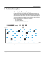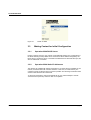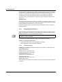
1
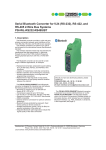
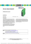
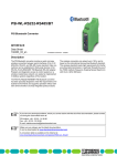
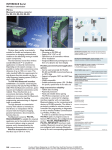
AUTOMATIONWORX
User Manual
UM EN FL BLUETOOTH AP
Order No.: 2888767
FL BLUETOOTH AP
AUTOMATIONWORX
User Manual
Hardware and Software of Bluetooth Access Points
- FL BLUETOOTH AP
07/2006
Designation:
UM EN FL BLUETOOTH AP
Revision:
00
Order No.:
2888767
This user manual is valid for:
FL BLUETOOTH AP
7281_en_00
PHOENIX CONTACT
Please Observe the Following Notes
In order to ensure the safe use of the product described, we recommend that you
read this manual carefully. The following notes provide information on how to use
this manual.
User Group of This Manual
The use of products described in this manual is oriented exclusively to qualified
electricians or persons instructed by them, who are familiar with applicable national
standards and other regulations regarding electrical engineering and, in particular,
the relevant safety concepts.
Phoenix Contact accepts no liability for erroneous handling or damage to products
from Phoenix Contact or third-party products resulting from disregard of information
contained in this manual.
Explanation of Symbols Used
The attention symbol refers to an operating procedure which, if not carefully
followed, could result in damage to hardware and software or personal injury.
The note symbol informs you of conditions that must strictly be observed to achieve
error-free operation. It also gives you tips and advice on the efficient use of
hardware and on software optimization to save you extra work.
The text symbol refers to detailed sources of information (manuals, data sheets,
literature, etc.) on the subject matter, product, etc. This text also provides helpful
information for the orientation in the manual.
We Are Interested in Your Opinion
We are constantly striving to improve the quality of our manuals.
Should you have any suggestions or recommendations for improvement of the
contents and layout of our manuals, please send us your comments.
PHOENIX CONTACT GmbH & Co. KG
Documentation Services
32823 Blomberg
Germany
Phone
Fax
E-mail
+49 - 52 35 - 30 0
+49 - 52 35 - 34 20 21
[email protected]
FL BLUETOOTH AP
General Terms and Conditions of Use for Technical Documentation
Phoenix Contact GmbH & Co. KG reserves the right to alter, correct, and/or improve the
technical documentation and the products described in the technical documentation at its
own discretion and without giving any notice.
The provision of technical documentation (in particular data sheets, installation
instructions, manuals, etc.) does not constitute any further duty on the part of
Phoenix Contact GmbH & Co. KG to furnish information on alterations to products and/or
technical documentation. Any other agreement shall only apply if expressly confirmed in
writing by Phoenix Contact GmbH & Co. KG. Please note that the supplied documentation
is product-specific documentation only.
Although Phoenix Contact GmbH & Co. KG makes every effort to ensure that the
information content is accurate, up-to-date, and state-of-the-art, technical inaccuracies
and/or printing errors in the information cannot be ruled out.
Phoenix Contact GmbH & Co. KG does not offer any guarantees as to the reliability,
accuracy or completeness of the information provided. Phoenix Contact GmbH & Co. KG
accepts no liability or responsibility for errors or omissions in the content of the technical
documentation (in particular data sheets, installation instructions, manuals, etc.).
As far as is permissible by applicable jurisdiction, no guarantee or claim for liability for
defects whatsoever shall be granted in conjunction with the information available in the
technical documentation, whether expressly mentioned or implied. This information does
not include any guarantees on quality, does not describe any fair marketable quality and
does not make any claims as to quality guarantees or guarantees on the suitability for a
special purpose.
Phoenix Contact GmbH & Co. KG reserves the right to alter, correct, and/or improve the
information and the products described in the information at its own discretion and without
giving any notice.
7281_en_00
PHOENIX CONTACT
FL BLUETOOTH AP
Statement of Legal Authority
This manual, including all illustrations contained herein, is copyright protected. Use of this
manual by any third party is forbidden. Reproduction, translation, or electronic and
photographic archiving or alteration requires the express written consent
of Phoenix Contact. Violators are liable for damages.
Phoenix Contact reserves the right to make any technical changes that serve the purpose
of technical progress.
Phoenix Contact reserves all rights in the case of patent award or listing of a registered
design. Third-party products are always named without reference to patent rights. The
existence of such rights shall not be excluded.
Internet
Up-to-date information on Phoenix Contact products can be found on the Internet at:
www.phoenixcontact.com
Make sure you always use the latest documentation.
It can be downloaded at:
www.download.phoenixcontact.com
A conversion table is available on the Internet at:
www.download.phoenixcontact.com/general/7000_en_00.pdf
PHOENIX CONTACT
7281_en_00
Table of Contents
Table of Contents
1
2
FL BLUETOOTH AP................................................................................................................1-1
1.1
Properties........................................................................................................... 1-1
1.1.1
Device Properties ............................................................................... 1-1
1.1.2
Features and Fields of Application of the BTAP ................................. 1-2
1.2
Supported Bluetooth Profiles ............................................................................. 1-2
1.3
Approvals for Countries...................................................................................... 1-3
1.4
Mounting the BTAP ............................................................................................ 1-4
1.4.1
Mounting the BTAP on a Flat Surface ................................................ 1-4
1.4.2
DIN Rail Mounting/Removal of the BTAP ........................................... 1-4
1.5
Installation/Interfaces of the FL BLUETOOTH AP ............................................. 1-5
1.5.1
Connecting the Supply Voltage .......................................................... 1-6
1.5.2
Status and Diagnostic Indicators ........................................................ 1-6
1.5.3
Assignment of Ethernet Cables .......................................................... 1-7
1.5.4
V.24 (RS-232) Interface ...................................................................... 1-8
Technical Description ..............................................................................................................2-1
2.1
3
Adaptive Frequency Hopping ............................................................................. 2-1
Startup and Configuration........................................................................................................3-1
7281_en_00
3.1
Default Upon Delivery/Default Settings.............................................................. 3-1
3.2
Initial Startup ...................................................................................................... 3-1
3.2.1
Reset to Activate the Configuration Settings ...................................... 3-1
3.3
Making Contact for Initial Configuration ............................................................. 3-2
3.3.1
Operation With DHCP Server ............................................................. 3-2
3.3.2
Operation With Static IP Addresses ................................................... 3-2
3.3.3
Assigning IP Parameters .................................................................... 3-4
3.3.4
Supported Bluetooth Profiles .............................................................. 3-8
3.4
Web-Based Management (WBM) ...................................................................... 3-9
3.4.1
Starting WBM ..................................................................................... 3-9
3.4.2
Password Protection for WBM ..........................................................3-11
3.5
Firmware Update..............................................................................................3-24
3.5.1
Establishing the FTP Connection .....................................................3-24
3.6
Configuration Examples ...................................................................................3-26
3.6.1
Manually Configured Multi-Point Solution (Wireless Switch) ............3-26
3.6.2
Roaming for a Mobile Client Using Two Access Points ....................3-32
3.6.3
Connect to Name Function ...............................................................3-39
3.6.4
Terminal Server Function .................................................................3-44
PHOENIX CONTACT
i
FL BLUETOOTH AP
4
Basics, Antenna Accessories, and Calculation Example for a Radio Path .............................4-1
4.1
5
Technical Data.........................................................................................................................5-1
5.1
ii
Wireless Technology Basics .............................................................................. 4-1
4.1.1
Wave Dispersion ................................................................................ 4-1
4.1.2
Assembling the BTAP in a Control Cabinet ........................................ 4-2
4.1.3
Antenna Accessories .......................................................................... 4-3
4.1.4
Example Calculation for a Transceiver System .................................. 4-4
4.1.5
Calculation for the Emitted Power ...................................................... 4-4
PHOENIX CONTACT
Ordering Data..................................................................................................... 5-3
5.1.1
Products ............................................................................................ 5-3
5.1.2
Accessories ........................................................................................ 5-3
7281_en_00
FL BLUETOOTH AP
1
FL BLUETOOTH AP
1.1
Properties
The FL BLUETOOTH AP (BTAP) is a Bluetooth access point, which is suitable for
industrial use. The BTAP supports Bluetooth specification 2.0 and has an RJ45 port with
10/100 Mbps with auto negotiation and a Bluetooth radio interface.
Figure 1-1
1.1.1
–
–
–
–
Front view of the BTAP
Device Properties
Secure data transmission using 128-bit encryption.
Support of LAN, PAN, and SPP Bluetooth profiles.
Time delay through the radio path less than 15 ms (typical - for a PROFINET frame
point-to-point)
Configurable range of 0.1 m to 250 m outdoors.
The range can be clearly exceeded or underattained and depends on the environment
and the antenna technology used.
–
–
–
7281_en_00
Roaming of an Ethernet client between several Bluetooth access points supported.
Diagnostics of the radio path link quality.
Automatic regulation of the transmission power.
PHOENIX CONTACT
1-1
FL BLUETOOTH AP
1.1.2
–
–
–
–
–
–
–
–
Features and Fields of Application of the BTAP
Reliable transmission of Ethernet data in harsh industrial environments.
Parallel operation of multiple radio cells.
Cyclic data transmission of low volumes of data.
Operation of up to seven clients at a single access point.
Mobile operation and monitoring.
Communication between control systems with low volumes of data via Bluetooth.
I/O data traffic with PROFINET IO systems via Bluetooth.
Simultaneous transmission of several serial connections via Bluetooth.
1.2
Supported Bluetooth Profiles
Personal Area Networking (PAN)
–
–
–
Transparent tunneling of Ethernet Layer 2 protocols.
Maximum of seven simultaneous connections supported.
The FL BLUETOOTH AP can be operated as an access point as well as a client.
The PAN profile defines ad hoc networking without servers between two to eight devices.
One wired access point (NAP - Network Access Point) provides access to the Ethernet
LAN for up to seven clients (PANU - PAN User). For additional information about using the
PAN profile, please refer to "Personal Area Networking (PAN)" on page 3-8.
LAN Access Profile (LAP)
–
–
PPP connection between the access point and a mobile termination device.
Only Layer 3 IP traffic via Bluetooth permitted.
The LAP profile networks devices using TCP/IP not only within local networks, but also
enables access to other networks. LAP uses the Point-to-Point Protocol (PPP) for
authentication, which always requires a server (BTAP). For additional information about
using the LAP profile, please refer to "LAN Access Profile (LAP)" on page 3-8.
Serial Port Profile (SPP)
–
COM server function for converting serial data packed into Ethernet frames to the
serial Bluetooth profile.
The SPP profile emulates a serial interface, which is used by other applications that were
originally designed for communication via V.24 (RS-232). For additional information about
using the SPP profile, please refer to "Serial Port Profile (SPP)" on page 3-9.
1-2
PHOENIX CONTACT
7281_en_00
FL BLUETOOTH AP
1.3
Approvals for Countries
The FL BLUETOOTH AP is a Bluetooth access point that is used to create radio cells. The
device uses the international toll and license-free Bluetooth standard, which operates in
the 2.4 GHz ISM band. This enables global use.
The device meets all the requirements of R&TTE directive 1999/5/EC (Europe):
– EMC according to EN 61000-6-2:2001
– Safety according to EN 60950:2001
– Health according to the recommendations of Gazette 1999/519/EC
– Radio according to ETSI EN 300328; V1.2.1, V1.4.1
The following additional approvals have also been performed and passed:
– FCC/CFR 47, Part 15 (USA)
– RSS 210 (Canada)
Depending on the maximum possible transmission power, the operation of this device
must be approved or notified in some countries. In addition, usage restrictions may apply
for the transmission power for indoor or outdoor use.
The FL BLUETOOTH AP has a maximum transmission power of 100 mW (20 dBm) and
corresponds to R&TTE device class 2. At the time of going to print, the operation of this
device had been approved/notified for the following countries (please observe the
corresponding usage restrictions):
–
Austria
20 dBm
–
Great Britain
20 dBm
–
Norway
20 dBm
–
Belgium
20 dBm
–
Greece
20 dBm
–
Poland
20 dBm
–
Canada
20 dBm
–
Hungary
20 dBm
–
Portugal
20 dBm
–
Cyprus
20 dBm
–
Iceland
20 dBm
–
Slovakia
20 dBm
–
Czech
Republic
20 dBm
–
Ireland
20 dBm
–
Slovenia
20 dBm
–
Denmark
20 dBm
–
Italy *
10 dBm
–
Spain
20 dBm
–
Estonia
20 dBm
–
Latvia
20 dBm
–
Sweden
20 dBm
–
Finland
20 dBm
–
Lithuania
20 dBm
–
Switzerland
20 dBm
–
France *
10 dBm
–
Luxembourg
20 dBm
–
The Netherlands 20 dBm
–
Germany
20 dBm
–
Malta
20 dBm
–
USA
20 dBm
Approvals for other countries are available on request.
* Usage restrictions:
France:
A maximum transmission power of 10 mW (10 dBm) is permitted outside buildings. Webbased management should be used to adapt the transmission power with the inclusion of
the antenna data.
Italy:
A license is required to use the device outside buildings. A maximum transmission power
of 10 mW (10 dBm) is permitted. Web-based management should be used to adapt the
transmission power with the inclusion of the antenna data.
7281_en_00
PHOENIX CONTACT
1-3
FL BLUETOOTH AP
1.4
Mounting the BTAP
A minimum distance of 50 cm between modules must be observed when mounting the
BTAPs.
1.4.1
Mounting the BTAP on a Flat Surface
Mount the BTAP on a flat mounting surface and secure the BTAP with two screws (e.g.,
with 84-M3 X 25-8.8 pan head screws). For the required drill hole spacing, refer to
Figure 1-2 on page 1-4.
If the BTAP is assembled in a control cabinet, the antenna must be led outside. For a list
of possible applications, calculation example, and corresponding accessories, please
refer to "Antenna Accessories" on page 4-3.
Drill Hole Template and Housing Dimensions
63 mm
2.480 in.
42 mm
1.654 in.
21 mm
0.827 in.
30 mm
1.181 in.
1.4.1.1
FL BLUETOOTH AP
Bluetooth Access Point
Ord No.: 27 37 999
FL BLUETOOTH AP
Bluetooth Access Point
Ord No.: 27 37 999
LAN
Bluetooth
5 mm
0.197 in.
70 mm
2.756 in.
Figure 1-2
1.4.2
5 mm
0.197 in.
10 mm
0.394 in.
21 mm
0.827 in.
42 mm
1.654 in.
LAN
Bluetooth
72810001
80 mm
3.150 in.
Housing dimensions and drill hole template for the BTAP in millimeters
(inches)
DIN Rail Mounting/Removal of the BTAP
Mount the DIN rail adapter provided on the back of the BTAP. Make sure the adapter and
BTAP are positioned correctly (see diagram below). To mount, place the upper holding
keyway of the adapter on the top edge of the DIN rail and push onto the housing from
above (A). Now push the bottom edge of the housing towards the DIN rail until the adapter
snaps onto the DIN rail (B).
To remove, push on the housing from above (A) and pull the bottom edge away from the
DIN rail (B).
1-4
PHOENIX CONTACT
7281_en_00
FL BLUETOOTH AP
A
Top
B
Figure 1-3
72810013
DIN rail mounting
A minimum distance of 50 cm between modules must be observed when mounting the
BTAPs.
If the BTAP is assembled in a control cabinet, the antenna must be led outside. For a list
of possible applications, calculation example, and corresponding accessories, please
refer to "Antenna Accessories" on page 4-3.
1.5
Installation/Interfaces of the FL BLUETOOTH AP
Antenna
Fixing holes
Supply voltage connection
Network
connection
FL BLUETOOTH AP
Bluetooth Access Point
Ord No.: 27 37 999
LAN
72810000
Bluetooth
Diagnostic/status
indicators
Figure 1-4
7281_en_00
V.24 (RS-232)
serial interface
View/interfaces of the BTAP
PHOENIX CONTACT
1-5
FL BLUETOOTH AP
–
–
–
–
–
–
Fixing holes
These holes can be used to fix the BTAP onto a flat mounting surface with two screws
(e.g., with 84-M3 X 25-8.8 pan head screws) (for drill hole spacing see Figure 1-2 on
page 1-4).
Antenna
The device is supplied with a 0 dB omni-directional antenna. The supplied antenna can
be replaced with another antenna in accordance with the relevant national regulations.
Supply voltage connection
The supply voltage is connected via the 2-pos. COMBICON connector.
Network connection
Copper interface in RJ45 format with 10/100 Mbps with auto negotiation.
V.24 (RS-232) serial interface
V.24 (RS-232) interface in (9-pos.) D-SUB format - no function at present.
Status and diagnostic indicators
The LEDs indicate the status of the Ethernet and Bluetooth interfaces.
1.5.1
24 V DC
Connecting the Supply Voltage
The BTAP is operated with a 24 V DC voltage.
- +
24 V DC
Figure 1-5
1.5.2
Supply to the BTAP
Status and Diagnostic Indicators
Three LEDs are located on the front of the device, which indicate various states.
1-6
PHOENIX CONTACT
7281_en_00
FL BLUETOOTH AP
FL BLUETOOTH AP
Bluetooth Access Point
Ord No.: 27 37 999
1
2
3
LAN
Bluetooth
Figure 1-6
Des.
Color
)))
(LED 1)
Blue/
green
LEDs on the front of the device
Status
Meaning
Green ON
The device was successfully started and is ready to operate
Green and blue
flashing
Blue ON
Attempting to establish a connection to another Bluetooth device
A Bluetooth connection has been established
Blue flashing
Transmitting data
Three green and Configuration modified, the device is waiting to be reset
one blue flashing
signal
Green flashing
LAN
(LED 2)
Yellow/
green
The device is in the error state
ON (green)
Ethernet link present
ON (yellow)
Ethernet communication active
OFF
No Ethernet connection
LED 3
No function
1.5.3
Assignment of Ethernet Cables
To connect the BTAP to an infrastructure component (e.g., switch), a 1:1 cable or line
cable is required.
RJ45
Figure 1-7
7281_en_00
1:1
Pin 1
RD+
n.c.
Pin 8
Pin 2
RD-
n.c.
Pin 7
Pin 3
TD+
RD- Pin 6
Pin 4
n.c.
n.c.
Pin 5
Pin 5
n.c.
n.c.
Pin 4
Pin 6
TD-
RJ45
RD+ Pin 3
Pin 7
n.c.
TD-
Pin 2
Pin 8
n.c.
TD+
Pin 1
72810006
Assignment of a 1:1 network cable
PHOENIX CONTACT
1-7
FL BLUETOOTH AP
To connect the BTAP to a termination device (e.g., computer), a crossover cable is
required.
RJ45
Figure 1-8
1.5.4
Cross Over
Pin 1
RD+
n.c.
Pin 8
Pin 2
RD-
n.c.
Pin 7
Pin 3
TD+
TD-
Pin 6
Pin 4
n.c.
n.c.
Pin 5
Pin 5
n.c.
n.c.
Pin 4
Pin 6
TD-
TD+
Pin 3
Pin 7
n.c.
RD-
Pin 2
Pin 8
n.c.
RD+
Pin 1
RJ45
72810007
Assignment of a crossover cable
V.24 (RS-232) Interface
The V.24 (RS-232) interface does not have a function at present.
1-8
PHOENIX CONTACT
7281_en_00
Technical Description
2
Technical Description
2.1
Adaptive Frequency Hopping
In order to achieve a high level of reliability during data transmission, the BTAP uses
adaptive frequency hopping. Data transmission with adaptive frequency hopping takes
place over the entire 2.4 GHz frequency band, where the 79 hopping channels change up
to 1600 times per second. If a channel is used or disturbed by another radio signal, the
channel is removed from the hopping sequence. This ensures that neither the Bluetooth
signal to be transmitted, nor the other radio service is disturbed. In addition to frequency
hopping, other properties ensure rugged wireless transmission:
– High receiver sensitivity
– Very short data telegrams
– Error correction mechanisms
– Repetition in the event of transmission errors
6 5 4 3 2
Information
1
Channels
Time
Figure 2-1
7281_en_00
Principle of data transmission
PHOENIX CONTACT
2-1
FL BLUETOOTH AP
2-2
PHOENIX CONTACT
7281_en_00
Startup and Configuration
3
Startup and Configuration
3.1
Default Upon Delivery/Default Settings
By default upon delivery or after the system is reset to the default settings, the following
functions and properties are available:
– The user name for WBM is "admin", the password is "admin".
– The Bluetooth PIN number is "32825".
– The BTAP is supplied with the following IP parameters:
IP address:
10.0.0.100
Subnet mask: 255.255.255.0
Gateway:
0.0.0.0
– DHCP is activated as the addressing mechanism.
3.2
Initial Startup
When the devices are started for the first time individually (i.e., without radio contact with
another Bluetooth device) with default settings, the automatic pairing function is activated
and "PhoenixAccessPoint" appears in the "PAN remote peers" field.
If the second device (also with default settings) is then switched on, the devices connect
to one another and form a transparent Ethernet connection.
Following successful connection establishment, the automatic pairing function is switched
off for both devices. On one of the devices, the entry in the "PAN remote peers" field is
deleted, leaving the field empty. On the other device, the "PAN remote peers" field contains
the MAC address of the first device.
3.2.1
Reset to Activate the Configuration Settings
The configuration settings are only applied when the Reset button is pressed. Please note
that all modified settings will be overwritten.
7281_en_00
PHOENIX CONTACT
3-1
FL BLUETOOTH AP
Figure 3-1
3.3
3.3.1
"Reset" in WBM
Making Contact for Initial Configuration
Operation With DHCP Server
If there is a DHCP server in your network, it automatically assigns an IP configuration to
the BTAP following startup. WBM can be accessed via the IP address assigned by the
DHCP server. The device can be connected to the DHCP server via the Ethernet port, but
also via a Bluetooth connection.
3.3.2
Operation With Static IP Addresses
The devices are supplied with fixed IP parameters. If no DHCP server is available in your
network, the BTAP starts with a fixed IP address. In this case, for initial contact your
computer must be configured so that contact is possible. The following screenshots were
created under Windows XP Professional.
To set the IP parameters, open the Properties tab for your network adapter. Activate
"Internet Protocol (TCP/IP)" and then click on "Properties".
3-2
PHOENIX CONTACT
7281_en_00
Startup and Configuration
Figure 3-2
Properties dialog box for the network card
In the dialog box that opens, click on "Use the following IP address".
Figure 3-3
7281_en_00
Internet Protocol Properties dialog box
PHOENIX CONTACT
3-3
FL BLUETOOTH AP
Enter the desired IP address in the "IP address" field. The first three bytes of the address
must be "10.0.0.". The last byte must contain a number between 1 and 254, but not 100,
the value "1" is selected in the example. See also 3.3.3 "Assigning IP Parameters".
"255.255.255.0" must be set as the subnet mask, close the dialog boxes with "OK".
The device can now be accessed via a web browser. Enter the following address in the
address line:
http://10.0.0.100
The user name and password only have to be entered on configuration pages where the
device settings can be modified. After entering the IP address in the browser, an overview
page is displayed for the BTAP where no login is required.
After the correct user name and password have been entered the device configuration
pages are loaded.
3.3.3
Assigning IP Parameters
When the supply voltage is switched on, the BTAP sends requests to the DHCP server to
assign IP parameters. If no DHCP server is available in the network, the BTAP uses the
fixed IP address (10.0.0.100) set by default upon delivery.
The "DHCP" function can be deactivated via the management. By default upon delivery,
the "DHCP" function is activated.
The assignment of valid IP parameters is vital to the operation of the BTAP.
Options for Assigning IP Parameters:
–
–
Configuration via the DHCP protocol (default upon delivery)
Static configuration via the management interfaces
3.3.3.1
Valid IP Parameters
IP parameters comprise the following three elements: "IP address", "subnet mask", and
"default gateway/router".
Valid IP addresses are:
000.000.000.001 to 126.255.255.255
128.000.000.000 to 223.255.255.255
Valid multicast addresses are:
224.000.000.001 to 239.255.255.255
Valid subnet masks are:
255.000.000.000 to 255.255.255.252
Default gateway/router:
The IP address of the gateway/router must be in the same subnetwork as the address of
the switch.
3-4
PHOENIX CONTACT
7281_en_00
Startup and Configuration
3.3.3.2
Assigning IP Addresses
The IP address is a 32-bit address, which consists of a network part and a user part. The
network part consists of the network class and the network address.
There are currently five defined network classes; Classes A, B, and C are used in modern
applications, while Classes D and E are hardly ever used. It is therefore usually sufficient
if a network device only "recognizes" Classes A, B, and C.
B it 1
B it 3 2
6 1 4 6 A 0 5 6
Figure 3-4
Position of bits within the IP address
With binary representation of the IP address the network class is represented by the first
bits. The key factor is the number of "ones" before the first "zero". The assignment of
classes is shown in the following table. The empty cells in the table are not relevant to the
network class and are already used for the network address.
Bit 1
Bit 2
Bit 3
Bit 4
Class A
0
Class B
1
0
Class C
1
1
0
Class D
1
1
1
0
Class E
1
1
1
1
Bit 5
0
The bits for the network class are followed by those for the network address and the user
address. Depending on the network class, a different number of bits are available, both for
the network address (network ID) and the user address (host ID).
Network ID
Host ID
Class A
7 bits
24 bits
Class B
14 bits
16 bits
Class C
21 bits
8 bits
Class D
28-bit multicast identifier
Class E
27 bits (reserved)
IP addresses can be represented in decimal or hexadecimal form. In decimal notation,
bytes are separated by dots (dotted decimal notation) to show the logical grouping of the
individual bytes.
The decimal points do not divide the address into a network and user address. Only the
value of the first bits (before the first "zero") specifies the network class and the number
of remaining bits in the address.
7281_en_00
PHOENIX CONTACT
3-5
FL BLUETOOTH AP
Possible Address Combinations
C la s s A
0 .0 .0 .0 - 1 2 7 .2 5 5 .2 5 5 .2 5 5
0
C la s s B
1 2 8 .0 .0 .0 - 1 9 1 .2 5 5 .2 5 5 .2 5 5
1
7 b its
2 4 b its
N e tw o r k ID
H o s t ID
C la s s C
1 9 2 .0 .0 .0 - 2 2 3 .2 5 5 .2 5 5 .2 5 5
0
1
1
1 4 b its
1 6 b its
N e tw o r k ID
H o s t ID
0
2 1 b its
8 b its
N e tw o r k ID
H o s t ID
2 8 b its
C la s s D
2 2 4 .0 .0 .0 - 2 3 9 .2 5 5 .2 5 5 .2 5 5
1
1
1
0
Id e n tifie r fo r m u ltic a s t g r o u p
2 7 b its
C la s s E
2 4 0 .0 .0 .0 - 2 4 7 .2 5 5 .2 5 5 .2 5 5
Figure 3-5
3.3.3.3
1
1
1
1
0
R e s e r v e d fo r fu tu r e a p p lic a tio n s
Structure of IP addresses
Special IP Addresses for Special Applications
Certain IP addresses are reserved for special functions. The following addresses should
not be used as standard IP addresses.
127.x.x.x Addresses
The Class A network address "127" is reserved for a loopback function on all computers,
regardless of the network class. This loopback function may only be used on networked
computers for internal test purposes.
If a telegram is addressed to a computer with the value 127 in the first byte, the receiver
immediately sends the telegram back to the transmitter.
The correct installation and configuration of the TCP/IP software, for example, can be
checked in this way.
As Layers 1 and 2 of the ISO/OSI reference model are not included in the test they should
be tested separately using the ping function.
Value 255 in the Byte
Value 255 is defined as a broadcast address. The telegram is sent to all the computers that
are in the same part of the network. Examples: 004.255.255.255, 198.2.7.255 or
255.255.255.255 (all the computers in all the networks). If the network is divided into
subnetworks, the subnet masks must be observed during calculation, otherwise some
devices may be omitted. Simplified: The last address of an area is reserved as the
broadcast address.
3-6
PHOENIX CONTACT
7281_en_00
Startup and Configuration
0.x.x.x Addresses
Value 0 is the ID of the specific network. If the IP address starts with a zero, the receiver
is in the same network. Example: 0.2.1.1 refers to device 2.1.1 in this network.
The zero previously signified the broadcast address. If older devices are used,
unauthorized broadcast and complete overload of the entire network (broadcast storm)
may occur when using the IP address 0.x.x.x.
3.3.3.4
Subnet Masks
Routers and gateways divide large networks into several subnetworks. The IP addresses
for individual devices are assigned to specific subnetworks by the subnet mask. The
network part of an IP address is not modified by the subnet mask. An extended IP
address is generated from the user address and subnet mask. Because the masked
subnetwork is only recognized by the local computers, this extended IP address appears
as a standard IP address to all the other devices.
Structure of the Subnet Mask
The subnet mask always contains the same number of bits as an IP address. The subnet
mask has the same number of bits (in the same position) set to "one", which is reflected in
the IP address for the network class.
Example: An IP address from Class A contains a 1-byte network address and a 3-byte
computer address. Therefore, the first byte of the subnet mask may only contain "ones".
The remaining bits (three bytes) then contain the address of the subnetwork and the
computer. The extended IP address is created when the bits of the IP address and the bits
of the subnet mask are ANDed. Because the subnetwork is only recognized by local
devices, the corresponding IP address appears as a "normal" IP address to all the other
devices.
Application
If the ANDing of the address bits gives the local network address and the local subnetwork
address, the device is located in the local network. If the ANDing gives a different result,
the data telegram is sent to the subnetwork router.
Example for a Class B subnet mask:
D e c im a l r e p r e s e n ta tio n : 2 5 5 .2 5 5 .1 9 2 .0
B in a r y r e p r e s e n ta tio n :
1 1 1 1 1 1 1 1 .1 1 1 1 1 1 1 1 .1 1 0 0 0 0 0 0 .0 0 0 0 0 0 0 0
S u b n e t m a s k b its
C la s s B
Using this subnet mask, the TCP/IP protocol software differentiates between the devices
that are connected to the local subnetwork and the devices that are located in other
subnetworks.
Example: Device 1 wants to establish a connection with device 2 using the above subnet
mask. Device 2 has IP address 59.EA.55.32.
IP address display for device 2:
7281_en_00
PHOENIX CONTACT
3-7
FL BLUETOOTH AP
H e x a d e c im a l r e p r e s e n ta tio n : 5 9 .E A .5 5 .3 2
B in a r y r e p r e s e n ta tio n :
0 1 0 1 1 0 0 1 .1 1 1 0 1 0 1 0 .0 1 0 1 0 1 0 1 .0 0 1 1 0 0 1 0
The individual subnet mask and the IP address for device 2 are then ANDed bit-by-bit by
the software to determine whether device 2 is located in the local subnetwork.
ANDing the subnet mask and IP address for device 2:
S u b n e t m a s k :
1 1 1 1 1 1 1 1 .1 1 1 1 1 1 1 1 .1 1 0 0 0 0 0 0 .0 0 0 0 0 0 0 0
A N D
IP a d d re s s :
0 1 0 1 1 0 0 1 .1 1 1 0 1 0 1 0 .0 1 0 1 0 1 0 1 .0 0 1 1 0 0 1 0
R e s u lt:
0 1 0 1 1 0 0 1 .1 1 1 0 1 0 1 0 .0 1 0 0 0 0 0 0 .0 0 0 0 0 0 0 0
S u b n e tw o rk
After ANDing, the software determines that the relevant subnetwork (01) does not
correspond to the local subnetwork (11) and the data telegram is forwarded to a
subnetwork router.
3.3.4
Supported Bluetooth Profiles
3.3.4.1
Personal Area Networking (PAN)
The Bluetooth profile can be used to create wireless networks whose devices are located
at close range.
– Transparent tunneling of Ethernet Layer 2 protocols.
– Maximum of seven simultaneous connections supported.
– The FL BLUETOOTH AP can be operated as an access point as well as a client.
The PAN profile defines ad hoc networking without servers between two to eight devices.
One wired access point (NAP) provides access to the Ethernet LAN for up to seven clients
(PANUs). An NAP can be connected to up to seven PANUs. A PANU can establish one
connection either to an NAP or to another PANU.
3.3.4.2
LAN Access Profile (LAP)
The LAP Bluetooth profile enables Bluetooth devices to access local networks.
– PPP connection between the access point and a mobile termination device.
– Only Layer 3 IP traffic via Bluetooth permitted.
The LAP profile networks devices using TCP/IP not only within local networks, but also
enables access to other networks. LAP uses the Point-to-Point Protocol (PPP) for
authentication, which always requires a server.
3-8
PHOENIX CONTACT
7281_en_00
Startup and Configuration
3.3.4.3
Serial Port Profile (SPP)
The SPP Bluetooth profile can be used to establish a serial connection between two
Bluetooth devices. The serial port is emulated according to the RFCOMM Bluetooth
protocol.
– COM server function for converting serial data packed into Ethernet frames to the
serial Bluetooth profile.
The SPP profile emulates a serial interface, which is used by other applications that were
originally designed for communication via V.24 (RS-232).
3.4
Web-Based Management (WBM)
The pages in WBM contain static information (e.g., the device type) as well as dynamic
information, such as the time or status information.
3.4.1
Starting WBM
To start WBM for the BTAP, enter the currently valid IP address in the address line of your
browser in the following format: http://10.0.0.100 (default).
If the BTAP is connected correctly and the addresses for the PC and BTAP are in the same
area, the following window is displayed:
Figure 3-6
Start window display
WBM is divided into the following functional groups:
– Overview
– Time
– User (password required)
7281_en_00
PHOENIX CONTACT
3-9
FL BLUETOOTH AP
–
–
–
–
Network (password required)
Bluetooth (password required)
Backup (password required)
Reset (password required)
Their subgroups are illustrated in the figure below.
http://10.0.0.100
Overview
System Overview
General
System Time
Bluetooth
Network
Web Server
Time
Set Date and Time
System Time
User
User Management
Services
Add User
Add Access Limit
View Users
View Access Limits
Delete User
Delete Access Limit
Save/Load Configuration
Save User Configuration
Load User Configuration
Network
Ethernet
PPP
Common
Bluetooth
General
Fieldbus
PAN
PAN Add Device
Search for Devices
Specify Name
Specify Address
Terminal Server
TS Add Device
Search for Devices
Specify Name
Specify Address
Backup
Create Backup
Reset
Reset System
Figure 3-7
3-10
PHOENIX CONTACT
Structure of WBM
7281_en_00
Startup and Configuration
3.4.2
Password Protection for WBM
In each session, when clicking for the first time on a menu item that requires a password,
the following window appears:
Figure 3-8
Access point or client login page
By default upon delivery use the following settings to log in:
User name:
admin
Password:
admin
3.4.2.1
"Overview" menu
The "Overview" page contains a wide range of information, which is divided into five areas:
– General
– System time
– Bluetooth
– Network
– Web server
General
The device firmware ID, including the creation date, and the device status are listed under
"General".
System time
The values set by the user for the time and date are listed under "System time".
Bluetooth
The access point name and the currently valid password for establishing a Bluetooth
connection are listed under "Bluetooth". In addition, connections that are currently active
are displayed together with their signal quality.
Network
The available parameters, such as MAC address, IP address, etc. are displayed under
"Network".
Web server
Indicates the homepage set for WBM.
7281_en_00
PHOENIX CONTACT
3-11
FL BLUETOOTH AP
3.4.2.2
"Time" Menu
The current system time is displayed here. To set another time, overwrite the fields in the
specified format and confirm with "Set Date and Time".
Figure 3-9
3.4.2.3
"Set Date and Time" menu
"User" Menu
In the "User" menu, various users can be created with different access rights. The access
rights for each individual web page can be defined. Each user can be assigned an access
level. Each web page can be assigned an access limit. To access a web page, the user's
access level must be equal to or greater than the web page access limit.
An access limit of "5" is preset for all configuration pages, so that only users with the
highest access level, i.e., level "5", can access the web pages.
If a page is assigned a lower access limit, users with a correspondingly lower level can also
access the pages.
In addition, settings for the user-specific configuration file can be made here.
Figure 3-10
3-12
PHOENIX CONTACT
"User" menu
7281_en_00
Startup and Configuration
Add User
"Add User" can be used to add additional users. To do this, the user name and the
individual password for the user are required. The access level is also set here.
Table 3-1
Access Level
User Rights
1
Level 1 rights (minimum access)
2
Level 1 and 2 rights
3
Level 1, 2, and 3 rights
4
Level 1, 2, 3, and 4 rights
5
Level 1, 2, 3, 4, and 5 rights (maximum access)
Figure 3-11
7281_en_00
User rights depending on the access level
"Add User" menu
PHOENIX CONTACT
3-13
FL BLUETOOTH AP
Add Limit
Access limits for each individual web page can be added under "Add Limit". To call the web
page, the user's access level must be at least as high as the access limit. In addition, the
access limit for the web page is set here.
Table 3-2
Web Page
Access Limit
User Rights Required to Call the Web Page
1
1, 2, 3, 4 or 5
2
2, 3, 4 or 5
3
3, 4 or 5
4
4 or 5
5
5
Figure 3-12
View Users
PHOENIX CONTACT
"Add Access Limit" menu
Under "View Users", all registered users can be viewed in list form together with their user
name and corresponding access level.
Figure 3-13
3-14
Required user rights depending on the access limit
"View Users" menu
7281_en_00
Startup and Configuration
View (Access) Limits
A list of the access limits currently valid for the individual web pages is displayed here.
Figure 3-14
Delete User
"View (Access) Limits" menu
Existing users can be deleted here.
Do not delete all users. At least one user must always be registered.
Figure 3-15
7281_en_00
"Delete User" menu
PHOENIX CONTACT
3-15
FL BLUETOOTH AP
Delete Access Limit
In the "Delete Access Limit" menu, the access rights for web pages can be removed.
Figure 3-16
"Delete Access Limit" menu
"Save/Load Configuration" Menu
Save User Configuration
In this menu, click on "Save" to save the user-specific settings or rights.
Figure 3-17
Load User Configuration
3-16
PHOENIX CONTACT
"Save (User) Configuration" menu
A previously saved configuration can be loaded here.
7281_en_00
Startup and Configuration
Figure 3-18
3.4.2.4
"Load Configuration" menu
"Network" Menu
In the "Network" menu, all settings are made, which affect the RJ45 Ethernet interface.
Network/Ethernet
The currently valid IP parameters are displayed in the "Ethernet" area. The IP address and
subnet mask can be overwritten.
If the IP parameters are adjusted and saved with "Save", the BTAP can no longer be
accessed from the moment that you click on "Reset". The device can be accessed using
the new IP address.
7281_en_00
PHOENIX CONTACT
3-17
FL BLUETOOTH AP
Under "DHCP", address assignment via DHCP can be activated/deactivated.
}
}
}
Figure 3-19
IP parameters for
access to WBM
Required if the LAP
profile is used
Required if WBM is
to be accessed
via a router
"Network" menu
Use of the LAP profile:
The LAP profile (Layer 3 transparent) uses a PPP connection between BTAP and the
Bluetooth termination device, therefore only IP data traffic is possible.
PPPO local: IP address of the BTAP for the PPP/LAN connection.
PPPO remote: IP address of the termination device. This IP address is assigned to the
termination device by the BTAP.
Use of the LAP profile:
When using the LAN profile, the BTAP acts as a proxy for the DNS requests from the
connected Bluetooth termination device. So that these requests can be forwarded to the
correct WINS or DNS server, the necessary settings must be made in the "Network"
menu under "Common".
"PPP use DHCP" selection
A DHCP server can also be used to assign the PPP IP addresses. If the function is
activated, the entries under "PPPO local" or "PPPO remote" are irrelevant if a DHCP server
is available.
Common
Under "Common", the necessary entries are made if configuration via WBM is to be
accessed using a router.
3-18
PHOENIX CONTACT
7281_en_00
Startup and Configuration
3.4.2.5
"Bluetooth" Menu
In the "Bluetooth" menu, all settings are made, which affect the Bluetooth interface.
Figure 3-20
Bluetooth/General
"Bluetooth" menu
In the "General" menu, basic Bluetooth settings are made.
Local name: Bluetooth name of the BTAP. The "Local Name" can be used to configure a
Bluetooth connection.
Passkey: Security key for encryption (alphanumeric entry supported). The passkey must
be identical for devices that are to communicate with one another with security mode
switched on.
Security Mode: Switches the security function on or off. When Security Mode is switched
on, the highest level of Bluetooth encryption is selected, in addition the passkey is
requested for pairing.
Data Policy: Here, the transmission type for data packets can be specified.
7281_en_00
PHOENIX CONTACT
3-19
FL BLUETOOTH AP
•
•
•
Short Delay (default) with medium data throughput and short latency times
(approximately 15 ms). For "Short Delay", the packet length for the BTAP data is
specified as required when error correction is switched on. Possible packet lengths
are 0 to 17 bytes, 0 to 27 bytes or 0 to 121 bytes.
Increased Range - In this mode small packets are sent when error correction is
switched on, so that in the event of a transmission error only a small volume of data
has to be repeated.
High Speed with high data throughput (up to 600 kbps unidirectional) and at higher
latency times - The greatest data throughput is achieved in this mode. Packets with a
length of 0 to 339 bytes are sent when error correction is switched off.
Setting the Transmission Power
Please note that for a radio unit, the total from the set transmission power and the
antenna gain, minus the attenuation for cables, lines, and connectors must not exceed
the maximum country-specific value.
For the maximum country-specific values, please refer to "Approvals for Countries" on
page 1-3. For additional information, please refer to "Calculation for the Emitted Power"
on page 4-4.
Maximum Range: Here the range/transmission power of the Bluetooth transmitter can be
set in the following steps:
•
0.1 m/-50 dBm
•
1 m/-32 dBm
•
25 m/-5 dBm
•
50 m/1 dBm
•
100 m/6 dBm
•
250 m/14 dBm
Low Emission Mode: This mode should be switched on if other radio applications are
operated in the same frequency range (e.g., WLAN, other BTAPs).
Bluetooth/Fieldbus
The settings under "Fieldbus" for the serial interface are not relevant at present, but can be
used as follows.
PC
COM port
redirector
Ethernet
PAN
AP1
SPP
Ethernet
AP2
Serial
72810017
Figure 3-21
Principle for using the serial interface
Setting under AP1: Terminal server and entered as remote peer "AP2"
A PC with redirector software connected to AP1 can then control the serial port of AP2. The
serial connection operates parallel to the PAN connection.
Bluetooth/PAN
Configuration for PAN (Personal Area Network), for any Ethernet communication (Layer 3
transparent).
PAN Role: Selection for the BTAP to operate as a client or as an access point.
3-20
PHOENIX CONTACT
7281_en_00
Startup and Configuration
Operation as an access point - "NAP" (Network Access Point) setting
Operation as a client - "PANU" (Personal Area Network User) setting
Automatic pairing - If this function is activated, the BTAP automatically pairs itself with
another device that has the same "Local Name".
PAN Remote Peers
By clicking on "Edit", the connections that are to be established by the device can be
configured. Three versions are supported:
– Entry of the Bluetooth MAC address for the device with which a connection is to be
established.
– Entry of the "Local Name" for the device with which a connection is to be established.
– Click on "Search for Devices". The devices that can be accessed are displayed in list
form and can then be selected.
Note on using "Local Names"/"Device Names"
A connection is established to a device whose "Local Name" starts with the character
string entered, which thus enables a form of roaming. Example: The characters "AP" are
configured in the PANU. Two access points are available with the names "AP1" and
"AP2". The PANU connects to the first AP that can be accessed. If the connection is
aborted, a search is performed automatically to find an alternative.
3.4.2.6
Additional Bluetooth Devices
All Bluetooth devices that can be accessed are displayed in the "PAN Add Devices" menu.
By clicking in the checkbox, the device will be configured as a peer.
Figure 3-22
"PAN Add Devices" menu
Devices that can be accessed are listed with their "Device Address" and their "Device
Name".
7281_en_00
PHOENIX CONTACT
3-21
FL BLUETOOTH AP
Bluetooth/Terminal Server
The BTAP contains a terminal server. Here, devices that have physical serial interfaces are
configured. The port number indicates which serial data stream ("compressed" in TCP/IP)
is forwarded to which Bluetooth devices.
Example: The settings listed in the table result in a serial connection being established
from COM 3 (COM 4) on the PC via BTAP1 to Remote Device 1 (Remote Device 2).
Table 3-3
Typical terminal server settings
PC With Redirector
BTAP1 Connected to the PC
COM 3: 192.168.0.100 port: 1000
BTAP1 terminal server
COM 4: 192.168.0.100 port: 1001
Figure 3-23
3.4.2.7
Backup
3-22
PHOENIX CONTACT
Remote Devices
Remote Device 1: port number: 1000
Remote Device 2: port number: 1001
"Terminal Server" menu
"Backup" Menu
In the "Backup" menu you can choose whether a configuration file should be saved on an
external drive or whether a configuration file should be loaded on the BTAP.
7281_en_00
Startup and Configuration
Figure 3-24
3.4.2.8
"Backup" menu
"Reset" Menu
In order to activate configuration modifications, click on "Reset".
Reset
Figure 3-25
7281_en_00
"Reset" menu
PHOENIX CONTACT
3-23
FL BLUETOOTH AP
3.5
Firmware Update
The files for a firmware update can be transferred via FTP (File Transfer Protocol). To do
this, an FTP server or browser such as Microsoft Internet Explorer 6.0, which also supports
the File Transfer Protocol, is required. If using an FTP server, you must log into the BTAP
as the administrator (admin). Internet Explorer 6.0 is used in this example.
3.5.1
Establishing the FTP Connection
To establish the FTP connection, enter the following characters in the browser address line
(illustrated here with the currently valid IP address):
ftp://[email protected]
The following window appears; the messages that are displayed are not relevant.
Figure 3-26
FTP login
The IP address of your BTAP is displayed under "FTP Server". Under "User name"
(Benutzername), enter "admin" if it does not appear automatically. After entering the
correct password, the contents of the BTAP memory are displayed.
The password required for the update is supplied with the firmware version update.
3-24
PHOENIX CONTACT
7281_en_00
Startup and Configuration
Figure 3-27
FTP view of the BTAP under Windows XP
A Readme file is provided with the firmware, which describes in detail how to proceed.
First read the Readme file and follow the instructions.
7281_en_00
PHOENIX CONTACT
3-25
FL BLUETOOTH AP
3.6
Configuration Examples
3.6.1
Manually Configured Multi-Point Solution (Wireless Switch)
Aim: Using a BTAP that is connected to an Ethernet network (LAN) via a copper
connection, up to seven Bluetooth clients can access the LAN via Bluetooth.
LAN
Bluetooth_AP_1
FL BLUETOOTH AP
Bluetooth Access Point
Ord No.: 27 37 999
LAN
Bluetooth
BT_Client_2
BT_Client_1
FL BLUETOOTH AP
FL BLUETOOTH AP
Bluetooth Access Point
Ord No.: 27 37 999
Bluetooth Access Point
Ord No.: 27 37 999
LAN
Bluetooth
1
STP
I1
I5
I2
I6
I3
I7
I4
INLINE CONTROL
11
22
I8
11
22
I9
I10
I11
I12
11
22
Q1 E
Q2
Q3
Q4
11
STP
US
UM
UL
1
PLC
MRESET
RUN
FAIL
I1
22
11
22
I5
I2
I6
I3
I7
I4
10/100
LNK
ACT
100
INLINE CONTROL
ILC 350 ETH
11
22
I8
11
22
I9
I10
I11
I12
11
22
Q1 E
Q2
Q3
Q4
11
STP
US
UM
UL
11
11
11
11
1
2
22
22
22
22
2
3
33
33
33
33
3
22
11
22
BSA
4
44
44
44
44
4
INLINE CONTROL
I6
I7
11
22
I8
11
22
I9
I10
I11
I12
Q1 E
Q2
Q3
Q4
US
UM
UL
11
11
11
22
22
22
ILC 350 ETH
1
11
11
11
11
1
2
22
22
22
22
2
3
33
33
33
33
3
4
44
44
44
44
4
1
11
11
11
11
2
22
22
22
22
3
33
33
33
33
1
3
4
44
44
44
44
4
Ord.No.: 27 37 203
RESET
PRG
IL
RDY / RUN
BSA
PRG
IL
2
RDY / RUN
BSA
FAIL
FAIL
FAIL
PF
PF
PF
Figure 3-28
I5
I2
I4
LNK
ACT
100
Ord.No.: 27 37 203
RDY / RUN
I1
I3
10/100
RESET
IL
RUN
FAIL
RUN / PROG
ETH
ILC 350 ETH
1
Ord.No.: 27 37 203
RESET
PRG
PLC
MRESET
RUN
FAIL
RUN / PROG
ETH
LAN
Bluetooth
1
PLC
MRESET
RUN / PROG
10/100
LNK
ACT
100
FL BLUETOOTH AP
Bluetooth Access Point
Ord No.: 27 37 999
LAN
Bluetooth
ETH
BT_Client_3
5
55
55
55
5
5
55
55
55
5
5
55
55
55
5
6
66
66
66
6
6
66
66
66
6
6
66
66
66
6
Example configuration for a multi-point solution
Configuration:
The BTAP, which is used as the access point for the wireless network, should provide
access for clients with IP address "10.0.0.200" and local name "Bluetooth_AP_1".
The clients should be assigned IP address "10.0.0.201" and local name "BT_Client_1",
and so on.
3-26
PHOENIX CONTACT
7281_en_00
Startup and Configuration
3.6.1.1
Procedure
Network Settings for the Access Point
Start up the access point and start WBM. On the "Network" web page, enter the following
IP address under "Ethernet/Ip": 10.0.0.200
Save the settings with "Save".
Figure 3-29
IP address used in the example
Bluetooth Settings
Switch to the "Bluetooth" web page.
Under "General/Local Name", enter the desired name (Bluetooth_AP_1 in the example).
Make sure that the access point and clients have different "Local Names", otherwise the
clients may connect to one another.
It is recommended that the security function is switched on (Security mode: "on"). When
the security function is switched on, the passkey (default: 32825) must be the same on
all devices that are to communicate with one another.
7281_en_00
PHOENIX CONTACT
3-27
FL BLUETOOTH AP
Figure 3-30
Bluetooth settings used in the example
Under "PAN/PAN Role", select "NAP" (Network Access Point).
Save the settings with "Save" and restart the device.
All settings must be saved with "Save" and activated with a device restart.
Network Settings for the Client (Example for a Client)
Start up the client and start WBM. On the "Network" web page, enter the following IP
address under "Ethernet/Ip": 10.0.0.201
Save the settings with "Save".
3-28
PHOENIX CONTACT
7281_en_00
Startup and Configuration
Figure 3-31
IP address used in the example
Bluetooth Settings
Switch to the "Bluetooth" web page.
Under "General/Local Name", enter the desired name (BT_Client_1 in the example).
7281_en_00
PHOENIX CONTACT
3-29
FL BLUETOOTH AP
Figure 3-32
Bluetooth settings used in the example
Under "PAN/PAN Role", select "PANU" (Personal Area Network User).
Under "PAN", click on "Edit" (red arrow in Figure 3-32).
Under "PAN Add Device", click on "Search for Devices" (red arrow in Figure 3-33).
3-30
PHOENIX CONTACT
7281_en_00
Startup and Configuration
Figure 3-33
Searching for additional Bluetooth devices
All available Bluetooth devices are now displayed with their "Local Name" and MAC
address. Select the desired device(s) by activating the checkbox and saving with "Save".
After saving, the selected device appears in the list in Figure 3-33.
Figure 3-34
Display of Bluetooth devices that can be accessed
Save the settings with "Save" and restart the device. When the BT client is restarted, it
connects automatically to the "Bluetooth_AP_1" access point.
7281_en_00
PHOENIX CONTACT
3-31
FL BLUETOOTH AP
3.6.2
Roaming for a Mobile Client Using Two Access Points
Aim: A mobile client is to permanently remain in contact with a controller along its radius
of movement using one of two access points. The radius of movement for the client is
greater than the radio field coverage of one access point. See example illustration.
Controller
FL BLUETOOTH AP
FL BLUETOOTH AP
Bluetooth Access Point
Ord No.: 27 37 999
Bluetooth Access Point
Ord No.: 27 37 999
LAN
Bluetooth
AP 1
AP 2
Traverse path of the BT client
FL BLUETOOTH AP
Bluetooth Access Point
Ord No.: 27 37 999
LAN
Bluetooth
LAN
Bluetooth
Client
72810012
Figure 3-35
Example illustration for roaming
If an Ethernet switch is used to connect the access point to the controller, in the worst
case scenario after the client connection switches from one access point to the other,
the controller cannot communicate with the client for the duration of the aging
time of the switch. Make sure that the application connected to the client communicates
with the controller in the required time-slot pattern, in order to inform the switch of the
port change and to ensure the connection.
Configuration:
Both BTAPs, which are used as access points for the mobile client, should enable
permanent access for the client with IP address "10.0.0.100" and "10.0.0.200" and local
name "AP 1" and "AP 2".
The clients should be assigned IP address "10.0.0.150" and local name "Mobiler_Client",
and so on.
3-32
PHOENIX CONTACT
7281_en_00
Startup and Configuration
3.6.2.1
Procedure
Network Settings for the Access Points
Start up the access point and start WBM. On the "Network" web page, enter the following
IP address under "Ethernet/Ip": 10.0.0.200
Save the settings with "Save".
Figure 3-36
IP address used in the example
Bluetooth Settings
Switch to the "Bluetooth" web page.
Under "General/Local Name", enter the desired name (AP_2 in the example).
It is recommended that the security function is switched on (Security mode: "on"). When
the security function is switched on, the passkey (default: 32825) must be the same on
all devices that are to communicate with one another.
7281_en_00
PHOENIX CONTACT
3-33
FL BLUETOOTH AP
Figure 3-37
Bluetooth settings used in the example
Under "PAN/PAN Role", select "NAP" (Network Access Point).
Save the settings with "Save" and restart the device. Now set the configuration on the
second access point.
All settings must be saved with "Save" and activated with a device restart.
Network Settings for the Mobile Client
Start up the client and start WBM. On the "Network" web page, enter the following IP
address under "Ethernet/Ip": 10.0.0.150
Save the settings with "Save".
3-34
PHOENIX CONTACT
7281_en_00
Startup and Configuration
Figure 3-38
IP address used in the example
Bluetooth Settings
Switch to the "Bluetooth" web page.
Under "General/Local Name", enter the desired name (Mobiler_Client in the example).
7281_en_00
PHOENIX CONTACT
3-35
FL BLUETOOTH AP
Figure 3-39
Bluetooth settings used in the example
Under "PAN/PAN Role", select "PANU" (Personal Area Network User).
Under "PAN", click on "Edit" (red arrow in Figure 3-39).
Under "PAN Add Device", click on "Search for Devices" (red arrow in Figure 3-40).
3-36
PHOENIX CONTACT
7281_en_00
Startup and Configuration
Figure 3-40
Searching for additional Bluetooth devices
All available Bluetooth devices are now displayed with their "Local Name" and MAC
address. Select both desired devices by activating the checkbox and saving with "Save".
After saving, the selected devices appear in the list in Figure 3-40.
Figure 3-41
7281_en_00
Display of Bluetooth devices that can be accessed
PHOENIX CONTACT
3-37
FL BLUETOOTH AP
Save the settings with "Save" and restart the device. When the BT client is restarted, it
connects automatically to an access point that can be accessed and only switches to the
other access point when the first is no longer available.
All settings must be saved with "Save" and activated with a device restart.
3-38
PHOENIX CONTACT
7281_en_00
Startup and Configuration
3.6.3
Connect to Name Function
Aim: Using several BTAPs that are configured as access points, mobile clients are to
access an Ethernet network (LAN) without each client requiring knowledge of each access
point.
Configuration:
The BTAPs, which are used as access points for the wireless network, should provide
access for clients with IP addresses "10.0.0.201", "10.0.0202" and local name
"Phoenix_AP_1".
The clients should be assigned IP address "10.0.0.101" and local name "BT_Client_1",
and so on.
3.6.3.1
Procedure
Network Settings for the Access Point
Start up the access point and start WBM. On the "Network" web page, enter the following
IP address under "Ethernet/Ip": 10.0.0.200
Save the settings with "Save".
Figure 3-42
IP address used in the example
Bluetooth Settings
Switch to the "Bluetooth" web page.
Under "General/Local Name", enter the desired name (Phoenix_AP_1 in the example).
7281_en_00
PHOENIX CONTACT
3-39
FL BLUETOOTH AP
When using the Connect to Name function, the "Local Names" of the access points must
have the same character strings at the start and only differ with regard to the last
character. Example: "Phoenix_AP_1", "Phoenix_AP_2", "Phoenix_AP...".
Make sure that the access point and clients have different "Local Names", otherwise the
clients may connect to one another.
It is recommended that the security function is switched on (Security mode: "on"). When
the security function is switched on, the passkey (default: 32825) must be the same on
all devices that are to communicate with one another.
Figure 3-43
Bluetooth settings used in the example
Under "PAN/PAN Role", select "NAP" (Network Access Point).
Save the settings with "Save" and restart the device.
All settings must be saved with "Save" and activated with a device restart.
3-40
PHOENIX CONTACT
7281_en_00
Startup and Configuration
Network Settings for the Client (Example for a Client)
Start up the client and start WBM. On the "Network" web page, enter the following
IP address under "Ethernet/Ip": 10.0.0.101
Save the settings with "Save".
Figure 3-44
IP address used in the example
Bluetooth Settings
Switch to the "Bluetooth" web page.
Under "General/Local Name", enter the desired name (BT_Client_1 in the example).
7281_en_00
PHOENIX CONTACT
3-41
FL BLUETOOTH AP
Figure 3-45
Bluetooth settings used in the example
Under "PAN/PAN Role", select "PANU" (Personal Area Network User).
Under "PAN", click on "Edit" (red arrow in Figure 3-32).
In the blank fields of the same area, enter the "Local Names" of the access points (red
arrow in Figure 3-46). "Phoenix_AP" in the example.
3-42
PHOENIX CONTACT
7281_en_00
Startup and Configuration
Figure 3-46
Entering the Bluetooth access points
The client can now log into any access point whose "Local Name" starts with
"Phoenix_AP". Save the settings with "Save" and restart the device. When the BT client is
restarted, it connects automatically to the "Bluetooth_APxxx" access point.
7281_en_00
PHOENIX CONTACT
3-43
FL BLUETOOTH AP
3.6.4
Terminal Server Function
COM Port Redirector Software:
Serial device 1
– Select virtual COM port:
– Terminal server IP address:
– Terminal server port:
– Data transmission mode (if it can be set):
Serial device 2
– Select virtual COM port:
– Terminal server IP address:
– Terminal server port:
– Data transmission mode (if it can be set):
–
COM 3
10.0.0.10
1200
Raw data
COM 4
10.0.0.10
1201
Raw data
Data that is sent to COM 3 on the PC arrives at the D-SUB female connector of the PSI
device with the Bluetooth name "Serial Device 1"; for COM 4 this is "Serial Device 2". It
is assigned via the port number, which is entered under "Terminal Server Remote Peers"
in the COM port redirector software.
Bluetooth
PSI WL RS485 .../BT
BT Name: Serial Device 1
Terminal Server Remote Peers:
Remote Devices Port Number
Serial Device 1
1200
Serial Device 2
1201
...
...
Client
ILB ...
BT Name: Serial Device 2
PC with
COM port
redirector
BTAP
IP: 10.0.0.1
IP: 10.0.0.100
Client
ILB ...
72810004
Figure 3-47
3-44
PHOENIX CONTACT
"Terminal Server" configuration example
7281_en_00
Basics, Antenna Accessories, and Calculation Example for a Radio Path
4
Basics, Antenna Accessories, and Calculation Example
for a Radio Path
4.1
Wireless Technology Basics
Wireless technology is based on the propagation and receipt of electromagnetic waves.
These waves are not subject to wear of any kind, but respond in very different ways in
terms of propagation, dispersion, and reflection depending on their frequency. The
propagation of waves in an area is three dimensional and occurs at different strengths.
Numerous factors affect this propagation, however none of these factors can affect the
propagation to the extent that a signal is not safely detected at the receiver.
4.1.1
Wave Dispersion
Every electromagnetic wave has different dispersion properties depending on its
frequency. A simple comparison can be made between the wave dispersion in the 2.4 GHz
ISM range and wave dispersion for visible light.
Every material has a frequency-dependent attenuation, every surface material bends,
reflects, refracts, absorbs or disperses electromagnetic waves of any kind. This means that
every obstacle between the transmitter and receiver must be taken into account for data
transmission.
Transmission through the medium of air also attenuates the radio signal and is known as
free space attenuation. Free space attenuation can be calculated using the following
formula:
Free space attenuation = 32.4 + 20 x log (frequency in MHz) + 20 x log (distance in km)
For simple calculations in the 2.4 GHz band, the expression "32.4 + 20 x log 2400 MHz"
can be replaced by the constant value "100".
This results in the following simplified formula:
Free space attenuation = 100 + 20 x log (distance in km)
7281_en_00
PHOENIX CONTACT
4-1
FL BLUETOOTH AP
4.1.2
Assembling the BTAP in a Control Cabinet
If the BTAP is assembled in a control cabinet, the antenna must be led outside. For a list
of possible applications and corresponding accessories, please refer to "Antenna
Accessories" on page 4-3. For additional antenna accessories, please refer to
"Accessories" 5.1.2 on page 5-3.
FL BLUETOOTH AP
Bluetooth Access Point
Ord No.: 27 37 999
LAN
Bluetooth
72810015
Figure 4-1
Installation example in a control cabinet/box with
3 dBi vandalism-proof antenna
Assembly in a Control Cabinet/Box
FL BLUETOOTH AP
Bluetooth Access Point
Ord No.: 27 37 999
LAN
Bluetooth
72810016
Figure 4-2
4-2
PHOENIX CONTACT
Installation example in a control cabinet/box with
8 dBi panel antenna
7281_en_00
Basics, Antenna Accessories, and Calculation Example for a Radio Path
4.1.3
Antenna Accessories
Some applications require the use of special antennas, for example, to improve the quality
of a radio path or increase its range.
Example - Control Cabinet Assembly:
If the BTAP is assembled in a control cabinet, the antenna must be led outside as the radio
waves are shielded by the metal of the cabinet.
The table below illustrates the accessories suitable for a few example applications.
Example - Creation of a Radio Path:
Panel antennas, which are connected to the BTAP via antenna cables, are particularly
suitable for point-to-point connections over longer distances.
The use of an antenna with 6 dBi gain doubles the range (under appropriate conditions).
The table below illustrates the accessories suitable for a few example applications.
Table 4-1
Selection of antennas and accessories
Application
Accessory Required
Antenna on the device (default upon
delivery)
Omni-directional antenna with 0.5 m
cable
– Emits in all directions
– Mounting, e.g., on control cabinet
Omni-directional antenna, 0 dBi
(supplied as standard)
0.5 m pigtail:
RAD-PIG-EF316-SMA-SMA
(Order No. 2885618)
Adapter: RAD-ADP-SMA/F-SMA/F
(Order No. 2884541)
Omni-directional antenna, 0 dBi
(supplied as standard)
Vandalism-proof antenna, 3 dBi,
including cable,
RAD-ISM-2400-ANT-VAN-3-0-SMA
(Order No. 2885867)
Omni-directional antenna with 1.5 m
cable, well protected
– Easy mounting, e.g., on control
cabinet
– Emits in all directions
Panel antenna with 3 m or 5 m cable for
indoor installation
– Away from the control cabinet
– Point-to-point connection of fixed
units
– Longer ranges
Antenna Type Used
3 m antenna cable:
RAD-CAB-EF-142-3M
(Order No. 2884512)
8 dBi panel antenna,
RAD-ISM-2400-ANT-PAN-8-0
(Order No. 2867610)
5 m antenna cable:
RAD-CAB-EF-142-5M
(Order No. 2884525)
Additional antennas and application scenarios available on request.
Make sure that the permissible transmission power for your country is not exceeded.
See "Approvals for Countries" on page 1-3 and "Setting the Transmission Power" on
page 3-20.
7281_en_00
PHOENIX CONTACT
4-3
FL BLUETOOTH AP
4.1.4
Example Calculation for a Transceiver System
All attenuations and all gains along a transceiver path must be taken into account when
calculating the radio path. The transmission properties for the relevant frequency range
must be known for all components.
For example, for a path in the 2.4 GHz ISM band, all values are added together (gains with
positive sign, attenuations with negative sign):
Transmission power
P = 25.1 mW
+14.0
dBm
Transmitter cable
3 m cable
2 connectors
-2.9
-0.4
dB
dB
Transmitting antenna
Panel antenna
+8.0
dBi
Free space attenuation
Optimum line of sight 100 m
-80.0
dB
Receiving antenna
Panel antenna
+8.0
dBi
Receiver cable
3 m cable
2 connectors
-2.9
-0.4
dB
dB
Receiver sensitivity
-85 dBm
(must be viewed as positive)
+85.0
dBm
Final total
System reserve
+28.4
dB
For a stable wireless connection, the system reserve must be at least 10 dB.
4.1.5
Calculation for the Emitted Power
The country-specific, approved, emitted power (see "Approvals for Countries" on page 1-3)
must not be exceeded. This should be checked in particular when using gain antennas.
Example for Germany
Permissible emitted power: 20 dBm, maximum
Set transmission power
(see "Setting the Transmission Power" on page 3-20)
Antenna cable (attenuation)
Panel antenna (gain)
Emitted power (total)
+14 dBm
-4 dB
+8 dBi
18 dBm
The device can be operated in Germany with this setting as the value is below 20 dBm. If
the device were to be operated in Italy, for example, the transmission power would have to
be set to a lower power level, e.g., 6 dBm, so as not to exceed the overall maximum
permitted value of 10 dBm.
4-4
PHOENIX CONTACT
7281_en_00
Technical Data
5
Technical Data
General Data
Function
Bluetooth access point
Housing dimensions (width x height x depth) in mm
80 x 25 x 65
Permissible operating temperature
-30°C to +85°C
Permissible storage temperature
-40°C to +85°C
Degree of protection
IP20, DIN 40050, IEC 60529
Protection class
Class 3 VDE 0106; IEC 60536
Humidity
Operation
5% to 90%, no condensation
Storage
10% to 95%, no condensation
Air pressure
Operation
79.5 kPa to 108 kPa, 2000 m above sea level
Storage
70 kPa to 108 kPa, 3000 m above sea level
Mounting position
Vertically on a flat mounting surface
Connection to protective earth ground
Not required
Weight
95 g, typical
Supply Voltage (US1/US2 Redundant)
Connection
Via COMBICON; conductor cross section = 2.5 mm2, maximum
Nominal value
24 V DC (SELV)
Permissible voltage ranges
9 V DC to 30 V DC
Typical current consumption on US at 24 V DC
200 mA
Typical power consumption
5W
Interfaces
Number of Ethernet ports
1
Connection format
8-pos. RJ45 female connector on the access point
Connection medium
Twisted pair cable with a conductor cross section of 0.14 mm2 to 0.22 mm2
Cable impedance
100 Ohm
Transmission speed
10/100 Mbps, auto negotiation
Maximum network segment expansion
100 m
Default IP address
10.0.0.100, DHCP client activated by default upon delivery
Bluetooth interface
Version
Bluetooth 2.4 GHz up to 1 Mbps
Transmission power
14 dBm, maximum - automatically controlled or can be adjusted manually
Receiver sensitivity
-85 dBm
Radio modules that can be connected
7 in preparation
Supported profiles
LAP, PAN, SPP
Bluetooth antenna
Characteristic
Omni-directional antenna (can be replaced)
Gain
0 dBi
7281_en_00
PHOENIX CONTACT
5-1
FL BLUETOOTH AP
Interfaces (Continued)
Connection
SMA
Bluetooth functions
Operating mode
Access point, Ethernet client adapter (COM server)
Function
Bridge, P2P, MP, COM server
Configuration
Via web-based management
Security
128-bit data encryption
Mechanical Tests
Shock test according to IEC 60068-2-27
Operation: 25g, 11 ms period,
half-sine shock pulse
Storage/transport: 50g, 11 ms period,
half-sine shock pulse
Vibration resistance according to IEC 60068-2-6
Operation/storage/transport: 5g, 10 - 150 Hz, Criterion 3
Free fall according to IEC 60068-2-32
1m
Approvals
FCC/CFR 47 Part 15, ETS 300 328
Conformance With EMC Directives
Noise emission according to EN 55022
Class B
Radio interference field strengths according to EN 55022
Class A
Electrostatic discharge (ESD) according to EN 61000-4-2
Contact discharge: ±4 kV
Air discharge: ±8 kV
Electromagnetic fields according to IEC 61000-4-3
10 V/m; Criterion A
Conducted interference
according to IEC 61000-4-6
10 VRMS; Criterion A
Fast transients (burst)
according to IEC 61000-4-4
Data lines: 1 kV; Criterion B
Power supply lines: 0.5 kV; Criterion B
Surge voltages according to IEC 61000-4-5
Data lines: ±1 kV asymmetrical; Criterion B
Power supply lines: ±0.5 kV symmetrical/asymmetrical; Criterion B
Differences Between This Version and Previous Versions
Version 00: First version
5-2
PHOENIX CONTACT
7281_en_00
Technical Data
5.1
5.1.1
Ordering Data
Products
Description
Order Designation
Order No.
Pcs./Pck.
Bluetooth access point
FL BLUETOOTH AP
2737999
1
5.1.2
Accessories
Description
Order Designation
Order No.
Pcs./Pck.
Antenna with omni-directional characteristics
and wire wrap
Antenna connection
RAD-ISM-2400-ANT-OMNI-9-0
2867623
1
RAD-ISM-2400-ANT-PAN-8-0
2867610
1
RAD-ISM-2400-ANT-VAN-3-0-SMA
2885867
1
Mounting bracket for wall mounting the omni-directional antenna with
protection against vandalism
RAD-ANT-VAN-MKT
2885870
1
Coaxial antenna cable
Connection
Attenuation
Impedance
1m
MCX/SMA
2 dBi
50 Ω
RAD-PIG-EF316-MCX-SMA
2867678
1
Coaxial antenna cable
Connection
0.3 m
N female
connector/SMA
1.5 dBi
50 Ω
RAD-PIG-EF316-N-SMA
2867694
1
Gain
Degree of protection
Impedance
Horizontal emission angle
Vertical emission angle
∅ 40 to 60 mm
N female
connector
9 dBi
IP65
50 Ω
360°
15°
Panel antenna with directional characteristics and
wire wrap
Antenna connection
Gain
Degree of protection
Dimensions (W x H x D)
∅ 40 to 60 mm
SMA
8 dBi
IP55
101 x 80 x 20 mm
Antenna with omni-directional characteristics
and protection against vandalism
Antenna connection
Gain
Degree of protection
Impedance
Length of the connecting cable
Attenuation
Impedance
SMA connector
3 dBi
IP55
50 Ω
1.5 m
Adapter N (female) > N (female)
RAD-ADP-N/F-N/F
2867843
1
Adapter SMA (female) > SMA (female)
RAD-ADP-SMA/F-SMA/F
2884541
1
Adapter RSMA (female) > RSMA (female)
RAD-ADP-RSMA/F-RSMA/F
2884538
1
Surge protection - Total surge current (8/20) µs of 20 kA, insertion
attenuation at 2.4 GHz to 2.5 GHz < 0.3 dB, N female connector/
N female connector
CN-UB-280DC-BB
2818850
1
Surge protection - Total surge current (8/20) µs of 20 kA, insertion
attenuation at 2.4 GHz to 2.5 GHz < 0.3 dB, N male connector/N female
connector
CN-UB-280DC-SB
2818148
1
Sealing tape - Vulcanizing to protect adapters, splitters or cable
connection, watertight
RAD-TAPE-SV-25-10
2885812
1
RAD-CAB-EF142-3M
2884512
1
Antenna cable
3 m antenna cable, SMA (male) > SMA (male)
7281_en_00
PHOENIX CONTACT
5-3
FL BLUETOOTH AP
Description
Order Designation
Order No.
Pcs./Pck.
5 m antenna cable, SMA (male) > SMA (male)
RAD-CAB-EF142-5M
2884525
1
3 m antenna cable, N (male) > N (male)
RAD-CAB-EF393-3M
2867649
1
5 m antenna cable, N (male) > N (male)
RAD-CAB-EF393-5M
2867652
1
10 m antenna cable, N (male) > N (male)
RAD-CAB-EF393-10M
2867665
1
15 m antenna cable, N (male) > N (male)
RAD-CAB-EF393-15M
2885634
1
1 m pigtail, MCX (male) > SMA (male)
RAD-PIG-EF-316-MCX-SMA
2867678
1
0.5 m pigtail, MCX (male) > N (male)
RAD-PIG-EF-316-MCX-N
2867681
1
0.3 m pigtail, N (female) > SMA (male)
RAD-PIG-EF316-N-SMA
2867694
1
0.5 m pigtail, N (female) > N (male)
RAD-PIG-EF316-N-N
2867704
1
0.5 m pigtail, SMA (male) > SMA (male)
RAD-PIG-EF316-SMA-SMA
2885618
1
2
Pigtail
Gray RJ45 connector set for linear cable
FL PLUG RJ45 GR/2
2744856
Green RJ45 connector set for crossed cable
FL PLUG RJ45 GN/2
2744571
2
Assembly tool for RJ45 connector
FL CRIMPTOOL
2744869
1
Patchbox 8 x RJ45 CAT 5e pre-assembled, can be retrofitted
FL PBX 8TX
2832496
1
Patchbox 6 x RJ45 CAT 5e and 4 SC-RJ, glass pre-assembled, can be
retrofitted
FL PBX 6TX/4FX
2832506
1
Patch cable
Patch cable, CAT 5, pre-assembled, 0.3 m long
FL CAT5 PATCH 0,3
2832250
10
Patch cable, CAT 5, pre-assembled, 0.5 m long
FL CAT5 PATCH 0,5
2832263
10
Patch cable, CAT 5, pre-assembled, 1.0 m long
FL CAT5 PATCH 1,0
2832276
10
Patch cable, CAT 5, pre-assembled, 1.5 m long
FL CAT5 PATCH 1,5
2832221
10
Patch cable, CAT 5, pre-assembled, 2.0 m long
FL CAT5 PATCH 2,0
2832289
10
Patch cable, CAT 5, pre-assembled, 3.0 m long
FL CAT5 PATCH 3,0
2832292
10
Patch cable, CAT 5, pre-assembled, 5.0 m long
FL CAT5 PATCH 5,0
2832580
10
Patch cable, CAT 5, pre-assembled, 7.5 m long
FL CAT5 PATCH 7,5
2832616
10
Patch cable, CAT 5, pre-assembled, 10.0 m long
FL CAT5 PATCH 10
2832629
10
PHOENIX CONTACT GmbH & Co. KG
Flachsmarktstr. 8
32825 Blomberg
Germany
+49 - 52 35 - 30 0
+49 - 52 35 - 34 12 00
www.phoenixcontact.com
Worldwide Locations:
www.phoenixcontact.com/salesnetwork
HOTLINE:
Should problems occur that cannot be resolved with the help of this documentation, please
contact our hotline:
+49 - 52 35 - 34 18 88
[email protected]
5-4
PHOENIX CONTACT
7281_en_00