1
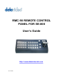
RMC-90 REMOTE CONTROL PANEL FOR SE-800 Users Guide http:// www.datavideo-tek.com Rev: 091105 Warnings and Precautions 1. Read all of these warnings and save them for later reference. 2. Follow all warnings and instructions marked on this unit. 3. Unplug this unit from the wall outlet before cleaning. Do not use liquid or aerosol cleaners. Use a damp cloth for cleaning. 4. Do not use this unit in or near water. 5. Do not place this unit on an unstable cart, stand, or table. The unit may fall, causing serious damage. 6. Slots and openings on the cabinet top, back, and bottom are provided for ventilation. To ensure safe and reliable operation of this unit, and to protect it from overheating, do not block or cover these openings. Do not place this unit on a bed, sofa, rug, or similar surface, as the ventilation openings on the bottom of the cabinet will be blocked. This unit should never be placed near or over a heat register or radiator. This unit should not be placed in a built-in installation unless proper ventilation is provided. 7. This product should only be operated from the type of power source indicated on the marking label of the AC adapter. If you are not sure of the type of power available, consult your Datavideo dealer or your local power company. 8. Do not allow anything to rest on the power cord. Do not locate this unit where the power cord will be walked on, rolled over, or otherwise stressed. 9. If an extension cord must be used with this unit, make sure that the total of the ampere ratings on the products plugged into the extension cord do not exceed the extension cords rating. 10. Make sure that the total amperes of all the units that are plugged into a single wall outlet do not exceed 15 amperes. 11. Never push objects of any kind into this unit through the cabinet ventilation slots, as they may touch dangerous voltage points or short out parts that could result in risk of fire or electric shock. Never spill liquid of any kind onto or into this unit. 12. Except as specifically explained elsewhere in this manual, do not attempt to service this product yourself. Opening or removing covers that are marked Do Not Remove may expose you to dangerous voltage points or other risks, and will void your warranty. Refer all service issues to qualified service personnel. 13. Unplug this product from the wall outlet and refer to qualified service personnel under the following conditions: a. When the power cord is damaged or frayed; b. When liquid has spilled into the unit; c. When the product has been exposed to rain or water; d. When the product does not operate normally under normal operating conditions. Adjust only those controls that are covered by the operating instructions in this manual; improper adjustment of other controls may result in damage to the unit and may often require extensive work by a qualified technician to restore the unit to normal operation; e. When the product has been dropped or the cabinet has been damaged; f. When the product exhibits a distinct change in performance, indicating a need for service. 1 Service and Support It is our goal to make your products ownership a satisfying experience. Our supporting staff is available to assist you in setting up and operating your system. Please refer to our web site www.datavideo-tek.com for answers to common questions, support requests or contact your local office below. Datavideo Corporation (USA) 12300-U East Washington Blvd., Whittier, CA 90606 USA Tel: +1 562 696 2324 [email protected] www.datavideo.us Datavideo Technologies Europe BV Californiedreef 26 3565 BL Utrecht, The Netherlands Tel: +31 30 261 9656 [email protected] www.datavideo.info Datavideo UK Limited Unit 2 Waterside Business Park, Hadfield, Glossop, Derbyshire SK13 1BE UK Tel: +44 1457 851000 [email protected] www.datavideo.info Datavideo Technologies Co., Ltd. 10F, 176 Jian-Yi Rd, Chung Ho City, Taipei Hsien, Taiwan 235 Tel: +886 2 8227 2888 [email protected] www.datavideo.com.tw Datavideo Technologies China Co. 2F-D, 2 Lane 777, West Guangzhong Rd, Zhabei District, Shanghai, China Tel: +86 21 5603 6599 [email protected] www.datavideo.cn Datavideo Technologies (S) PTE Ltd. No. 100, Lorong 23 Geylang, #01-03 DCentennial Bldg, Singapore 388398 Tel: +65 6749 6866 [email protected] www.datavideo.info 2 Warranty Datavideo warrants that the equipment it manufactures shall be free from defects in material and workmanship for a period of 12 months from the date of product purchased. If equipment fails due to such defects, Datavideo will, at its option, repair or provide a replacement for the defective part or product. Equipment that fails after the warranty period, has been operated or installed in a manner other than that specified by Datavideo, or has been subjected to abuse or modification, will be repaired for time and material charges at the Buyers expense. This warranty does not affect your statutory rights within the Country of purchase. For EU Customers only - WEEE Marking. This symbol on the product indicates that it will not be treated as household waste. It must be handed over to the applicable take-back scheme for the recycling of electrical and electronic equipment. For more detailed information about the recycling of this product, please contact your local Datavideo office. 3 CONTENTS INTRODUCTION 5 WHATS IN THE PACKAGE 5 CONTROL PANEL 6 REAR PANEL CONNECTION 10 MORE PERIPHERALS 12 4 Introduction RMC-90 is a Remote Control Panel especially designed to work with SE-800 control panel simultaneously. RMC-90 provides a wired remote function of video channel selection keys, programmable effect function keys, T-Bar control most of the control key functions from SE-800. It includes a Tally control for the Datavideo TLM-404 LCD panels and three GPI triggers to control Datavideo DV Bank. Whats in the Package 1. 2. 3. 4. 5. 6. 7. RMC-90 unit 15-pin D-sub TLM-404 LCD TALLY control cable 9-Pin D-sub RS-232 interface cable for connecting SE-800 GPI trigger cables for DV Bank control XLR male to XLR female power cable for connecting SE-800 DC cable, Plug with lock, 12V output. Users Guide 5 Control Panel Audio Select for channel A, B, C or D and A+V function key This row of selector buttons has a internal LED to show which input channel is active. If the A+V function key is engaged (LED on), the audio source channel selected on the Main Source bus is automatically selected. If A+V is not engaged, the input source is user selectable. Please refer to the Front Panel section of SE-800 instruction manual for a more detailed description. 6 Video Main-source and SUB-source Select for channel A, B, C or D and BK (Background) function key It is used to select which of the four video input channels or background will be selected as Main Source and which of the four video input channels or background will be transitioned to or used as a sub source in an effect. For more information, please refer to the Front Panel section of SE-800 instruction manual. 7 GPI-1 to GPI-3 Enable the three terminals GPI trigger output on rear panel for video play-pause control of Datavideo DV Bank F1-F10 and F11-20, F21-30 Control of the 30 users programmable preset locations for storing customized effects and transitions. The numbered buttons 1-10 above access 10 locations. To access F11 to F20, you need to first press the F11-20 button until the LED is lit, then press one of the single numbered buttons to access presets F11-F20. To access F21-F30, please follow the same procedure. To store or playback a transition or effect from preset function keys, please refer to the Front Panel section of SE-800 instruction manual for detail. 8 T-bar is for performing effect transitions manually. It can be either all the way up, all the way down, or anywhere in between. To enable SE-800 T-Bar, the T-Bar on RMC-90 need to be set at either end of its travel. PLEASE NOTE, T-Bar on RMC-90 CAN NOT CONTROL AN AUDIO ONLY FADE EFFECT, it controls only Video or Video with embedded audio effect. Press to turn on LED to enable the GPI Trigger input control on SE-800 Each press on this button will playback the pre-stored function keys effect sequentially Turn on LED to enable the T-Bar effect control for video Turn on LED to enable the T-Bar Audio effect control. Note: Push down the T-Bar to mute Audio Press on the button to Auto-Play the effect 9 Rear Panel connection GPI Trigger outputs to control DV Bank Trigger o/p +5V o/p Ground 10 Connect to Datavideo TLM-404 4x4 TFT LCD or connecting an certain adaptor cable to control the Tally interface of video input source devices, such as Came The D-Sub 15-pin connector works by closing contacts between a ground pin and the corresponding LED pin as following pin out table. *. Do not give power to the pins. GREEN Video RED LED Channel (On Air - Live) A Pin 1 Pin 2 Pin 3 B Pin 6 Pin 7 Pin 8 C Pin 11 Pin 12 Pin 13 D Pin 5 Pin 10 Pin 15 Connect to SE-800 Remote RS-232 interface Pin 2: RX, Pin 3: TX Pin 5: Ground Others: Not connected LED AMBER LED (Next - Cued) (OffLine - Safe) DC 12V 0.5A output to connect to external 12V DC powered peripherals DC 14.4 --- 15V output to SE-800 Power input Pin 1: Ground Pin 4: VCC DC 14.4 --- 15V input from SE-800 Power adaptor Pin 1: Ground Pin 4: VCC 11 More Peripherals Datavideo TLM-404 4x4 TFT LCD panel Datavideo DV Bank Native DV recorder and GPI Trigger cable Built-in 120GB HDD for 9 hours native DV backup recording DV Bank is the industry-standard, stand-alone solution that allows video professionals to capture digital video (DV) content directly to a high performance disk drive-based system while shooting or anytime afterwards. Once your video is captured on the DV Bank, it can be quickly and easily accessed in a non-linear fashion for in-field review and logging. DV Banks FireWire (IEEE-1394) interface allows direct capture from Digital camcorders, VTRs or Switchers. With its simple and dependable VTR-style controls, the DV Bank is very easy to use and integrates seamlessly with your existing studio and location equipment. 12 Datavideo BAC-03 Balanced-Unbalanced Audio converter The BAC-03 is a bi-directional unbalanced to balanced and balanced to unbalanced audio converter, with four independent amplifiers providing stereo audio input and output. SPECIFICATIONS UNBAL to BAL output BAL to UNBAL output INPUT LEVEL -10dBv nominal 0dBm to +8dBm nominal INPUT IMPED 50K ohms 0K ohm GAIN +4 to +20dB -20dB to +18dB OUTPUT LEVEL 0 to +8dBm nom, +22dBm max -10dBv nom, +20dBv max OUTPUT LOAD 600 ohms or higher, balanced 600 ohms or higher, unbalanced FREQ RESPONSE DC to 25kHz, +/-0.5dB DC to 25kHz, +/-0.5dB NOISE LEVEL 80dB below nom output level 80dB below nom output level DISTORTION <0.01% at any frequency <0.01% at any frequency POWER INPUT DIMENSION DC 12V, 200mA 140(W) x 112(D) x 40(H) mm All the trademarks are the properties of their respective owners. 13 Datavideo Technologies Co., Ltd. All rights reserved 2005. P/N: 082061305E2