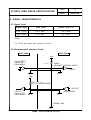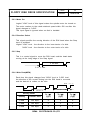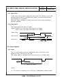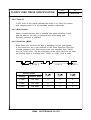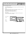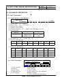
1
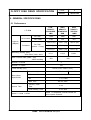
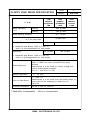
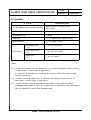
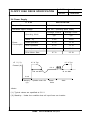
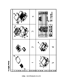
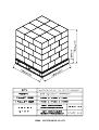
FDD
OEM MANUAL
SFD-321B
3.5inch DUAL DENSITY
MICRO FLOPPY DISK DRIVE
SPECIFICATIONS
SEMA ELECTRONICS CO.,LTD
XiaLingBei HengKeng Management Area
Liaobu Town Dongguan City
Guangdong Province, China
SEMA ELECTRONICS CO.,LTD
FLOPPY DISK DRIVE SPECIFICATION
PAGE
1
MODEL
SFD-321B
CONTENTS
1. INTRODUCTION
1.1 Application
1.2 Disk Used
2. GENERAL SPECIFICATIONS
2.1
2.2
2.3
2.4
2.5
Performance
Environmental Conditions
Reliability
Power Supply
Physical Specifications
3. INSTALLATION
4. ELECTRICAL INTERFACE
4.1 Signal Interface
4.2 Power Interface
4.3 Interface Connectors
5. SIGNAL CHARACTERISTICS
5.1
5.2
5.3
5.4
Signal Level
Recommended Interface Circuit
Input Signals
Output Signals
6. TIMING DIAGRAM
6.1 Seek Operation Timing
6.2 Read / Write Operation Timing
SEMA ELECTRONICS CO.,LTD
FLOPPY DISK DRIVE SPECIFICATION
PAGE
2
MODEL
SFD-321B
7. SAFETY STANDARDS
8. PACKAGING DESCRIPTION
8.1 Label Description
8.2 Packaging Method
8.3 Pallet Dimension and the Method
9. OPTION SELECTION
9.1 Trace Options
9.2 Other Options (Buyer Selection)
10. GENERAL COMMENT
※ LIST of FIGURES
Figure 2-1.
Physical Dimensions (With Bezel Type)
Figure 2-2.
Physical Dimensions (Without Bezel Type)
Figure 3-1.
Installation
Figure 4-1.
Signal Interface Connector and Cable Side Connector
Figure 4-2.
Power Interface Connector and Cable Side Connector
Figure 4-3.
Rear View of FDD
Figure 8-1.
Packaging Method
Figure 8-2.
Pallet Dimension & Method
SEMA ELECTRONICS CO.,LTD
FLOPPY DISK DRIVE SPECIFICATION
PAGE
3
MODEL
SFD-321B
1. INTRODUCTION
1.1 Application
This manual shall be applied for SAMSUNG SFD-321B - double side, dual
density (option : 3 mode), 3.5 inch micro floppy disk drive
(hereinafter referred to as "FDD").
1.2 Disk Used
3.5 inch micro floppy disks (hereinafter referred to as "DISK"),
the use of which will be mutually agreed between the customers and
SAMSUNG, shall be used.
SEMA ELECTRONICS CO.,LTD
FLOPPY DISK DRIVE SPECIFICATION
PAGE
4
MODEL
SFD-321B
2. GENERAL SPECIFICATIONS
2.1 Performance
LOW
DENSITY
STANDARD
1MB
HIGH
DENSITY
STANDARD
2MB
HIGH
DENSITY
*OPTION*
1.6MB
Per Disk
1000
2000
1600
Per Track
6.25
12.5
10.0
655.4 (16)
1310.7 (32)
1065.0 (26)
737.3 (9)
1474.6 (18)
1228.8 (15)
819.2 (5)
1638.4 (10)
1310.7 (8)
Recording Density (BPI)
-Inner Most Track, side 1
8,717
17,434
Data Transfer Rate (KBits / sec)
-MFM recording
250
I T E M
Unformatted
Capacity
(KBytes)
Formatted
Per Disk
(Sector / Track)
500
Number of Heads
2
Number of Tracks
160
Track Density (TPI)
135TPI (5.33 Tracks / mm)
Rotational Speed
Drive Motor
Specification
300 RPM
LSV
± 1.5 % Max.
ISV
± 1.5 % Max.
Start Time
Access Time
14,528
Track to Track
Time
Head Settling Time
Head 0 / Head 1 Offset
360 RPM
500 ms Max.
3 ms
15 ms Max.
Head 1 is displaced 8 tracks toward the
drive spindle direction.
SEMA ELECTRONICS CO.,LTD
FLOPPY DISK DRIVE SPECIFICATION
LOW
DENSITY
STANDARD
1MB
I T E M
Media Operating
Force
PAGE
5
MODEL
SFD-321B
HIGH
DENSITY
STANDARD
2MB
Inserting
800 gr Max.
Ejecting
1300 gr Max.
Media Ejecting Distance
10 ~ 70 mm
Acoustic Noise at 50 cm
- at 3 ms Step Rate
50 dBA Max.
Read Bit Shift
1300 ns Max.
HIGH
DENSITY
*OPTION*
1.6MB
650 ns Max.
1. Measured with Brikon 723B on Track 79
with 0 ns precompensation on both heads.
Asymmetry
600 ns Max.
300 ns Max.
1. Measured with Brikon 723B on Track 00
with 0 ns precompensation on both heads.
Radial Alignment
Both R/W heads must be radially aligned to all tracks
within ±0.0200 mm when accessed from either
direction.
Measurement is to be made at normal voltage and
normal environmental condition
(23±2 ℃ and 50±5 % RH)
Azimuth Alignment
±0 °18′Max.
Index to Data Burst
0 ~ 1300 μs
Measurement is to be made from the leading edge of
index pulse to the beginning of data burst on
Track 40.
Overwrite Modulation
-26 dB or less at Track 00
* Read/Write Compensation : 125ns is recommended
SEMA ELECTRONICS CO.,LTD
FLOPPY DISK DRIVE SPECIFICATION
PAGE
6
MODEL
SFD-321B
2.2 Environmental Conditions
ITEM
SPECIFICATION
Operating (℃)
Ambient
Temperature
0 ∼ 50
Storage (℃ )
-40 ∼ 70
Transportation (℃ )
-40 ∼ 70
Temperature Gradient
(℃ / Hr)
Operating
20 Max.
Non-operating
30 Max.
Operating : 29 ℃ Max. wet bulb temp.
Relative
Humidity (%)
*No-condensation
Vibration
(30 min. sweep
cycle)
*Exclude
resonant
frequency
Shock (11 ms
half sine wave)
Storage
20 ∼ 80
: 40 ℃ Max. wet bulb temp.
0 ∼ 90
Transportation : 45 ℃ Max.
wet bulb temp.
0 ∼ 90
5 ~ 100 Hz frequency range
1.5 G Max.
Operating 100~ 200 Hz frequency range
1.0 G Max.
200~ 600 Hz frequency range
0.5 G Max.
Transportation : 5 ~ 600 Hz
frequency range
3
G Max.
Operating
5
G Max.
Transportation
SEMA ELECTRONICS CO.,LTD
100
G Max.
FLOPPY DISK DRIVE SPECIFICATION
PAGE
7
MODEL
SFD-321B
2.3 Reliability
I T E M
SPECIFICATION
M.T.B.F.(Mean time between failures)
20000 power on hours (POH)
(25% duty)
M.T.T.R.(Mean time to repair)
30 minutes Max.
Component Life
5 years
Disk Life
3×10 6 passes per track or more
Disk Insertion
3×10 4 times or more
Error Rate
Soft Read Error
(*1)
1 per 10 9 bits read
Hard Read Error
(*2)
1 per 10 12 bits read
Seek Error
(*3)
1 per 10 6 seeks
<Note>
(*1)
A soft (recoverable) error is defined as a successful attempt to read a track
of data within 3 retries after a read failure.
A read retry is defined as an attempt to read the entire track that a read
failure occurred on.
(*2)
A hard (non-recoverable) error is defined as a failure to read a track of
data within 3 retries after a read failure.
(*3)
A seek (access) error is defined as the inability of the drive to seek to
a targeted track within 1 retry. An access retry is defined as one recalibration
with an attempt to seek to the targeted track.
SEMA ELECTRONICS CO.,LTD
FLOPPY DISK DRIVE SPECIFICATION
PAGE
8
MODEL
SFD-321B
2.4 Power Supply
I T E M
SPECIFICATION
Required Power
D.C. 5 V ± 10 %
Allowable Ripple Voltage
100 mVp-p (including spike noise)
Average Current
Average Power
Typ.
Typ.
Stand - by
2 mA
10mW
Read Operation
0.3 A
1.5 W
Write Operation
0.3 A
1.5 W
Seek Operation (3 ms)
0.7 A
3.5 W
Drive Motor Start
0.7 A
3.5 W
Operating Mode
Power
Consumption
+5 V (*1)
0.7 A Typ.
0.7 A Typ.
Current (A)
0.3 A
18 ms Max.
500 ms Max.
2 mA
Stand-by
Spindle motor ON
(*2)
Read /
Seek
Write
<Note>
(*1) Typical values are specified at 5.0 V
(*2) Stand-by : Under the condition that all input lines are inactive.
SEMA ELECTRONICS CO.,LTD
FLOPPY DISK DRIVE SPECIFICATION
PAGE
9
MODEL
SFD-321B
2.5 Physical Specifications
I T E M
Mechanical
Dimension
SPECIFICATION
Width (mm)
101.6
Height (mm)
25.4
Depth (mm)
Weight (gr)
145.0 (without Front Bezel)
460.0 typ.
External View
Refer to Fig. 2-1 and Fig. 2-2
Installation Holes
Refer to Fig. 2-1 and Fig. 2-2
SEMA ELECTRONICS CO.,LTD
SEMA ELECTRONICS CO.,LTD
SEMA ELECTRONICS CO.,LTD
SEMA ELECTRONICS CO.,LTD
FLOPPY DISK DRIVE SPECIFICATION
PAGE
13
MODEL
SFD-321B
4. ELECTRICAL INTERFACE
4.1 Signal Interface
Density Select
In Use (Spare)
Drive Select 3 (Spare)
Index
Drive Select 0
Drive Select 1
Drive Select 2 (Spare)
HOST
CONTROLLER
SYSTEM
Motor On
Direction Select
Step
Write Data
Write Gate
Track 00
Write Protect
Read Data
Side Select
Ready/Disk Change
2
4
6
8
10
12
14
FDD
16 SFD-321B(*1)
18
20
22
24
26
28
30
32
34
<Note>
(*1) All odd numbers : GND
4.2 Power Interface
+5 V
HOST
CONTROLLER
POWER
SUPPLY
+5 V Return (GND)
No Connection (GND)
No Connection
SEMA ELECTRONICS CO.,LTD
1
2
3
4
FDD
SFD-321B
FLOPPY DISK DRIVE SPECIFICATION
PAGE
14
MODEL
SFD-321B
4.3 Interface Connectors
4.3.1 Signal Interface Connector
Side
Connector
FDD
HIROSE P/N 5003-001-7347 or equivalent (*1)
HOST (Connector)
3M NO. 7934 or equivalent
HOST (Cable)
3M 3365/34 or equivalent (*2)
<Note>
(*1) 33 pins, 2.54 pitch (Pin #3,5,7,9,13,15,17,19,23,25,27,31 : cut off)
Wall Type
(*2) Cable length : 1m (3.3 feet) Max.
2 4
~
34
1 3
~
33
PCB
PIN NO.3,5,7,9,13,15,17,19,23,25,27,31 : Cut off
Rear View
FRONT
Top View
< Signal Interface Connector (FDD) >
< Cable Side Connector (HOST) >
Fig 4-1. Signal Interface Connector and Cable Side Connector
SEMA ELECTRONICS CO.,LTD
FLOPPY DISK DRIVE SPECIFICATION
PAGE
15
MODEL
SFD-321B
4.3.2 Power Interface Connector
Side
Connector
FDD
ELCO P/N 9251-004-000-809 or equivalent
HOST (Connector)
AMP 171822-4 or equivalent
HOST (Cable)
AWG #20-26
PCB
4 3 2 1
Rear View
Top View
< Power Interface Connector (FDD) >
< Cable Side Connector (HOST) >
Fig 4-2. Power Interface Connector and Cable Side Connector
SEMA ELECTRONICS CO.,LTD
FLOPPY DISK DRIVE SPECIFICATION
PAGE
16
MODEL
SFD-321B
5. SIGNAL CHARACTERISTICS
5.1 Signal Level
Signal Logic
Input Level
Output Level (*1)
Low (True)
0.9 V Max.
0.4 V Max.
High (False)
2.2 V Min.
2.4 V Min.
<Note>
(*1) "LOW" level Max. sink current is 48 mA.
5.2 Recommended Interface Circuit
HOST SIDE
FDD SIDE
Vdd
7438 SERIES
CMOS OR
EQUIVALENT
(1 ㏀ )
CMOS
(SCHMITT TRIGGER INPUT)
INPUT
Vdd
150 Ω∼ 2.2 ㏀
(1 ㏀ is recommended)
OUTPUT
74LS14
74HC14 OR
EQUIVALENT
OPEN DRAIN
FRAME GND
SEMA ELECTRONICS CO.,LTD
FLOPPY DISK DRIVE SPECIFICATION
PAGE
17
MODEL
SFD-321B
5.3 Input Signals
5.3.1 Density Select
This siganl is used to distinguish between 1.6MB and 2MB Mode.
The interface pin No.2 can be used as Density Select Input signal by
attaching 0 Ω resistor onto "OPA" short plug when the High density media
is inserted. The "HIGH" level designates 2MB Mode and the "LOW" level
designates 1.6MB Mode.
FDD can tell whether the inserted media is high
or Low density by checking the signal coming from mechanical switch which
detects the density selecting hole on the media.
Type
Contents
2 Mode
(2.0 / 1.0MB)
(Non-connection of "OPA")
Automatic Switching
2.0MB : If High density media is inserted.
1.0MB : If Low density media is inserted.
Automatic Switching with "Density Select"
3 Mode
(2.0 / 1.6 / 1.0MB)
(Connection of "OPA")
2.0MB : If High density media is inserted
with "Density Select" is "HIGH".
1.6MB : If High density media is inserted
with "Density Select" is "LOW".
1.0MB : If Low density media is inserted
"Density Select" is not available.
5.3.2 Drive Select 0 and 1
Two trace plugs on the PCB, DS0 and DS1 are provided to select which
Drive Select line will activate the interface signals for a unique drive in the
daisy chain connection up to two drive units. Drive Select, when activated
logical "LOW", enables all the I/O lines except Motor On line.
This signal also controls the lightening of In-Use LED.
SEMA ELECTRONICS CO.,LTD
FLOPPY DISK DRIVE SPECIFICATION
PAGE
18
MODEL
SFD-321B
5.3.3 Motor On
Logical "LOW" level of this signal makes the spindle motor be turned on.
The motor reaches to the rated rotational speed within 500 ms after this
signal changes to "LOW".
This input signal is ignored when no disk is installed.
5.3.4 Direction Select
This signal specifies the moving direction of the R/W head when the Step
input is activated.
Logical "LOW" level : the direction to the inner tracks of a disk.
"HIGH" level : the direction to the outer tracks of a disk.
5.3.5 Step
This is a control signal to move the R/W head, and the head starts
moving at the rising edge of the Step signal.
3 ms Min.
0.15 ㎲ Min.
5.3.6 Write Data(MFM)
Each time this signal changes from "HIGH" level to "LOW" level,
the direction of the current flowing into the R/W head is reversed,
and the data bit is written on the disk.
0.15 ~ 1.1 ㎲
Ta±0.5 %
Tc±0.5 %
Tb±0.5 %
Density Mode
Tw
Density
Transfer Rate
Ta (㎲ )
(Typ.)
Tb (㎲)
(Typ.)
Tc (㎲ )
(Typ.)
1.0MB
250 kbps
4
6
8
1.6MB
500 kbps
2
3
4
2.0MB
500 kbps
2
3
4
SEMA ELECTRONICS CO.,LTD
FLOPPY DISK DRIVE SPECIFICATION
PAGE
19
MODEL
SFD-321B
5.3.7 Write Gate
"LOW" level of this signal enables the write data to be written on the disk
provided that the drive is selected, disk used is not write protected and
seek operation is completed.
When this signal changes to "HIGH" level, the read or seek operation
becomes possible.
5.3.8 Side Select
This signal selects the side of Heads.
Logical "HIGH" level : the lower side (side 0) of Heads
"LOW " level : the upper side (side 1) of Heads
WRITE GATE
SIDE SELECT
READ DATA
100 ㎲ Min.
650 ㎲ Min.
100 ㎲ Min.
valid
100 ㎲ Min.
valid
valid
valid
650 ㎲ Min
5.4 Output Signals
5.4.1 Index
This is a pulse signal output to indicate the start of the track, and it
outputs at every revolution of the disk.
This output signal is activated when only the drive is in Ready state.
1∼8 ms
200±3 ms
(166.7±2.5 ms)(*1)
<Note>
(*1) The value in parenthsis is for 360 rpm (1.6MB Mode) rotation speed.
SEMA ELECTRONICS CO.,LTD
FLOPPY DISK DRIVE SPECIFICATION
PAGE
20
MODEL
SFD-321B
5.4.2 Track 00
"LOW" level of this signal indicates the head is on Track 00 position
and stepping motor is at the specified position respectively.
5.4.3 Write Protect
When a write-protected disk is inserted, this signal becomes "LOW"
and the data on the disk is protected from mis-erasing and
the write operation is inhibited.
5.4.4 Read Data (MFM)
Read Data read out from the disk is transferred to the host system
in the same form as it was received on the Write Data line. Each flux
reversal sensed on the disk produces the only transition from "HIGH"
level to "LOW" level. For the seperation of the clock bits from the data,
the leading edge of a change from "HIGH" to "LOW" level is used.
Ta±0.5 %
Tb±0.5 %
Density Mode
Tc±0.5 %
400 ns±20 %
Ta (㎲)
(Typ.)
Tb (㎲)
(Typ.)
Tc (㎲ )
(Typ.)
Density
Transfer Rate
1.0MB
250 kbps
4
6
8
1.6MB
500 kbps
2
3
4
2.0MB
500 kbps
2
3
4
SEMA ELECTRONICS CO.,LTD
FLOPPY DISK DRIVE SPECIFICATION
5.4.5
PAGE
21
MODEL
SFD-321B
Disk Change / Ready
By selecting proper trace plugs, this signal line (pin #34) can be used for
Ready or Disk Change line.
-. Ready
This line becomes active "LOW" when the drive is selected, a disk is
clamped and the spindle motor is up to speed.
(after counting at least two Index pulses)
Otherwise this line goes logical "HIGH" level.
-. Disk Change
This line is active "LOW" unless disk is clamped and a Step pulse is
received when the drive is selected.
DRIVE SELECT
DISK IN
inserted
ejected
STEP
DISK
CHANGE
0.5 ㎲ Max
SEMA ELECTRONICS CO.,LTD
0.5 ㎲ Max
FLOPPY DISK DRIVE SPECIFICATION
PAGE
22
MODEL
SFD-321B
6. TIMING DIAGRAM
6.1 Seek Operation Timing
DRIVE SELECT
DIRECTION
SELECT
FORWARD
REVERSE
500 ㎱ Min.
1 ㎲
1 ㎲ Min.
18 ㎳ Min. (*1)
Min.
STEP
1 ㎲
3 ㎳ Min.
2.8 ㎳ Max.
10 ㎲ Max.
Min.
TRACK 00
6.2 Read / Write Operation Timing
650 ㎲ Min.
MOTOR ON
650 ㎲ Min.
600 ㎳ Max.
DRIVE SELECT
0.3 ㎳ Max.
READY
STEP
(*2)
DENSITY
SELECT
READ DATA
18 ms Min.
100 ㎲ Min. (*3)
0 Min.
18 ms Min.
100 ㎲ Min (*3)
100 ㎲ Min. (*3)
(*2)
(*2)
WRITE GATE
0 Min.
8 ㎲ Max.
8 ㎲ Max.
WRITE DATA
<Note>
(*1) Turn Around Time is 18 ms Min. when Direction is changed.
(*2) 750㎲ Min. (including 100 ㎲ Side Select timing)
(*3) When spindle motor speed is changed (300 rpm ↔ 360 rpm)
this value is 500 ms Min.
SEMA ELECTRONICS CO.,LTD
FLOPPY DISK DRIVE SPECIFICATION
PAGE
23
MODEL
SFD-321B
7. SAFETY STANDARDS
This drive is approved by the followings;
.
.
.
.
.
.
.
CE
CSA
UL
TUV
MIC
BSMI
FCC
SAMSUNG ELECTRO-MECHANICS CO.,LTD.
SEMA ELECTRONICS CO.,LTD
FLOPPY DISK DRIVE SPECIFICATION
PAGE
24
MODEL
SFD-321B
8. PACKAGING DESCRIPTION
8.1 Label Description
8.1.1 Serial Number Label Marking
BAR CODE
FBT6
①
②
③
④
⑤
⑥
S1ARB00001
F
①
B
②
T
③
6
④
S
⑤
1
⑥
A
⑦
L
⑧
B 00001
⑨
⑩
Product name : "F" → FDD
Model name : "B" → SFD-321B
Revision name (Major)
Revision name (Minor)
Production division : "S" → SEMA ELECTRONICS CO.,LTD
Production site
Marking
1
2
Production site
China factory
(SEMA China)
Outside supplier
(OEM)
⑦ Production line : "A" → A-Line, "B" ~ "Z"
⑧ Year of manufacturing
Year
2001
2002
2003
2004
2005
2006
2007
Marking
M
N
P
Q
R
S
T
⑨ Month of manufacturing
Month
Marking
Month
Marking
Month
Marking
Month
Marking
1
1
4
4
7
7
10
A
2
2
5
5
8
8
11
B
3
3
6
6
9
9
12
C
⑩ Consecutive number
8.1.2 Label Description
Bar code
FBT6
S1R1100001①
SFD-321B /
****③
⑤
⑥
①
②
③
④
⑤
Serial number
Revision
Buyer name
Production site
CE marking
REV. T6②
DC5V 0.7V
⑦
⑧
MADE IN CHIN A ④
⑨
⑩
CSA marking
UL marking
TUV marking
MIC marking (for only domestic)
BSMI marking
⑪ Label manufacturer identification
⑥
⑦
⑧
⑨
⑩
SEMA ELECTRONICS CO.,LTD
⑪
SEMA ELECTRONICS CO.,LTD
SEMA ELECTRONICS CO.,LTD
FLOPPY DISK DRIVE SPECIFICATION
PAGE
27
MODEL
SFD-321B
9. OPTION SELECTION
FDD can be modified for different functions than the standard specification.
These modifications should be implemented by the factory according to the
request of the customers.
9.1 Trace Options
By putting a chip-resistor onto a proper trace, FDD can be used for the
following different functions.
Trace Name
Description
DS0
Activate Drive Select 0 line
DS1
Activate Drive Select 1 line
DC
Activate Disk Change Signal
RDY
Activate Ready Signal
OPA
For 3 Mode usage
OPB (*1)
For 1.6MB usage
<Note>
(*1) Both "OPA" and "OPB" open : 2 Mode (1MB / 2MB)
"OPB" is connected and "OPA" is open : 2 Mode (1MB / 1.6MB)
"OPA" is connected and "OPB" is open : 3 Mode (1MB / 1.6MB / 2MB)
SEMA ELECTRONICS CO.,LTD
FLOPPY DISK DRIVE SPECIFICATION
PAGE
28
MODEL
SFD-321B
9.2 Other Options (Buyer Selection)
The colors of In-Use LED, Front-Panel, the value of the termination resistors
and the shape of button can be modified by customers' request.
9.2.1 Mode
□
2 Mode (1MB / 2MB)
□
3 Mode (1MB / 1.6MB / 2MB)
9.2.2 The Selection of Bezel Type
□
With Bezel
□
Without Bezel
9.2.3 The Color of Bezel, Button
□
Black
□
Ivory
□
Gray
Color Number
(Fill in this blank)
9.2.4 The Selection of LED Color
□
Green
□
Red
□
Amber
SEMA ELECTRONICS CO.,LTD
FLOPPY DISK DRIVE SPECIFICATION
PAGE
29
MODEL
SFD-321B
11. GENERAL COMMENT
SEMA ELECTRONICS CO.,LTD
SEMA ELECTRONICS CO.,LTD