1
LCD TV
installation manual
imagine the possibilities
Thank you for purchasing this Samsung product.
To receive more complete service, please register
your product at
www.samsung.com/register
Model
BN68-02157K-x0-Eng.indd 1
Serial No.
2009-04-16 ¿ÀÈÄ 5:03:08
Instruction
This TV is provided with interactive functionality through a set-back box (SBB/STB) connected
to the TV, and with other TVs in a computer controlled system for hotels and other hospitality
businesses.
Interactive : When the TV is powered-up initially, it sends a command to identify the SBB/STB;
if identified, theTV switches to ONLINE mode and full control is through the SBB/STB.
If the TV is in ONLINE mode, it stops receiving IR(Samsung remote) commands and acts
according to interface protocol.
Stand-Alone: If SBB/STB is not identified, the TV should be switched to STAND-ALONE mode with
restricted operation.
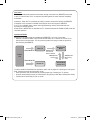
Operational Modes
When this TV (in Hotel mode) is operated with a SBB/STB, it is in one of two states
- ONLINE or STAND-ALONE. In the STAND-ALONE state, the TV will act as a Hotel TV, but
without active communication. This is to prevent guests from trying to cheat the system by
disconnecting the SBB/STB.
Hotel TV
Hotel Mode On
SBB/STB Onlineif one success
within 10 attempts
Power
ON
Stand-alone
Mode
SBB/STB Online10 consecutive
fails
Hotel Mode Off
Normal TV
SBB/STB StatusAttempt every
2secs
Online Mode
Poll Rate 20/sec
To set the details for Stand-alone or interactive mode, refer to pages 16-19(Setting the hotel option
data : Stand-alone mode and Interactive mode)
- Some operations may be restricted to prevents guests from "cheating" the TV system.
- No main menu(Interactive mode) or Channel Menu, Plug & Play in Main Menu (Stand-Alone mode)
- Limited Volume and Panel key lock or unlock
BN68-02157K-x0-Eng.indd 2
2009-04-16 ¿ÀÈÄ 5:03:08
Digital TV Notice
1. Functionalities related to Digital TV(DVB) are only available in countries/areas where DVB-T (MPEG2 and MPEG4 AVC)
digital terrestrial signals are broadcasted or where you are able to access to a compatible DVB-C(MPEG2 and MPEG4
AAC) cable-TV service. Please check with your local dealer the possibility to receive DVB-T or DVB-C signal.
2. DVB-T is the DVB European consortium standard for the broadcast transmission of digital terrestrial television and
DVB-C is that for the broadcast transmission of digital TV over cable. However, some differentiated features like EPG
(Electric Program Guide), VOD (Video on Demand) and so on, are not included in this specification. So, they cannot be
workable at this moment.
3. Although this TV set meets the latest DVB-T and DVB-C standards, as of [August, 2008], the compatibility with future
DVB-T digital terrestrial and DVB-C digital cable broadcasts cannot be guaranteed.
4. Depending on the countries/areas where this TV set is used some cable-TV providers may charge an additional fee for
such a service and you may be required to agree to terms and conditions of their business.
5. Some Digital TV functions might be unavailable in some countries or regions and DVBC might not work correctly with
some cable service providers.
6. For more information, please contact your local Samsung customer care centre.
Precautions When Displaying a Still Image
A still image may cause permanent damage to the TV screen
● Do not display a still image and partially still on the LCD panel for more than 2 hours as it can cause screen image retention.
This image retention is also known as “screen burn”. To avoid such image retention, reduce the degree of brightness and
contrast of the screen when displaying a still image.
Watching the LCD TV in 4:3 format for a long period of time may leave traces of borders displayed on the left, right
●
and centre of the screen caused by the difference of light emission on the screen. Playing a DVD or a game console
may cause a similar effect to the screen. Damages caused by the above effect are not covered by the Warranty.
● Displaying still images from Video games and PC for longer than a certain period of time may produce partial after-images.
To prevent this effect, reduce the ‘brightness’ and ‘contrast’ when displaying still images.
© 2009 Samsung Electronics Co., Ltd. All rights reserved.
BN68-02157K-x0-Eng.indd 3
2009-04-16 ¿ÀÈÄ 5:03:09
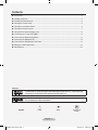
Contents
List of Parts.............................................................................................................................................2
Installing the Stand.................................................................................................................................2
Installing the Wall Mount Kit....................................................................................................................2
Viewing the Control Panel......................................................................................................................3
Viewing the Connection Panel................................................................................................................4
Viewing the Remote Control...................................................................................................................7
Using the Anti-Theft Kensington Lock.....................................................................................................8
Connecting the TV with STB (SBB)........................................................................................................9
Connecting the Bathroom Speakers.....................................................................................................11
Connecting the MediaHub HD..............................................................................................................13
Connecting the RJP(Remote Jack Pack).............................................................................................14
Setting the Hotel Option Data...............................................................................................................16
Specifications........................................................................................................................................26
License
TruSurround HD, SRS and symbol are trademarks of SRS Labs, Inc. TruSurround HD
technology is incorporated under license from SRS Labs, Inc.
Manufactured under license from Dolby Laboratories. Dolby and the double-D symbol
are trademarks of Dolby Laboratories.
Symbol
Press
Note
One-Touch
Button
English - 1
BN68-02157K-x0-Eng.indd 1
2009-04-16 ¿ÀÈÄ 5:03:10
List of Parts
Please make sure the following items are included with your LCD TV.
If any items are missing, contact your dealer.
M4 X L16
Remote Control &
Batteries (AAA x 2)
Power Cord
• Owner’s Instructions
Cover-Bottom
• Safety Guide
Data Cable
• Warranty card
Stand &
Cleaning Cloth
Stand Screw x 4
• Registration Cards
➣ Warranty card / Safety Guide / Registration Cards (Not available in all locations)
➣ The stand and stand screw may not be included depending on the model.
➣ The Data Cable may not be included depending on the SI Vendor.
Installing the Stand
2
1
1. Attach your LCD TV to the stand.
➣ Two or more people should carry the TV.
➣ Make sure to distinguish between the front and back of the stand when attaching it.
➣ To make sure the TV is installed on the stand at a proper level, do not apply excess downward
pressure to the upper left of right sides of the TV.
2. Fasten two screws at position 1 and then fasten two screws at position 2.
➣ Stand the product up and fasten the screws. If you fasten the screws with the LCD TV placed
down, it may lean to one side.
Installing the Wall Mount Kit
Wall mount items (sold separately) allow you to mount the
TV on a wall. For detailed information on installing the wall
mount, see the instructions provided with the Wall Mount
items. Contact a technician for assistance when installing
the wall mounted bracket. Samsung Electronics is not
responsible for any damage to the product or injury to
yourself or others if you elect to install the TV on your own.
Do not install your Wall Mount Kit while your TV is
turned on. It may result in personal injury due to
electric shock.
➣ Remove the stand and cover the bottom hole with the
cover.
English - BN68-02157K-x0-Eng.indd 2
2009-04-16 ¿ÀÈÄ 5:03:12
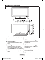
Viewing the Control Panel
1
2 3
4
5
6
7 8
3
4
5
6
7
8
2
1
➣ The product color and shape may vary depending on the model.
1 Speakers
2 Remote Control Sensor
Aim the remote control towards this spot on
the TV.
3 SOURCE
Toggles between all the available input sources
(TV, AV, Component, PC, HDMI1, HDMI2).
In the on-screen menu, use this button as you
would use ENTER button on the remote control.
4 MENU
Press to see an on-screen menu of your TV’s features.
5 +=Press to decrease or increase the volume.
In the on-screen menu, use the + = buttons as you use the ◄ and ► buttons on
the remote control.
6
CH
Press to change channels.
In the on-screen menu, use the CH
buttons as you use the ▼ and ▲ buttons on
the remote control.
7 Power Indicator
Blinks and turns off when the power is on and
lights up in stand-by mode.
8
(Power)
Press to turn the TV on and off.
English - BN68-02157K-x0-Eng.indd 3
2009-04-16 ¿ÀÈÄ 5:03:14
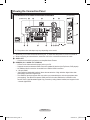
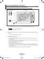
Viewing the Connection Panel
LE32B550M2H/LE37B550M2H/LE40B550M2H/LE46B550M2H
[TV Rear Panel]
1
2
3
4
[TV Side Panel]
5
HDMI IN2
2
IN 1
6
Power Input
7
%
➣
@
$
#
! 0 9 8
The product color and shape may vary depending on the model.
➣ Whenever you connect an external device to your TV, make sure that power on the unit is turned off
➣ When connecting an external device, match the color of the connection terminal to the cable.
1 AUDIO OUT
- Connects to the audio input jacks on an Amplifier/Home Theater.
2 HDMI(DVI) IN 1 / AUDIO / PC / HDMI IN 2
- Connect to the video and audio output jack on your PC.
- Supports connections between HDMI-connection-enabled AV devices (Set-Top Boxes, DVD players).
- No additional Audio connection is needed for an HDMI to HDMI connection.
➣ What is HDMI?
- "High Definition Multimedia interface" allows the transmission of high definition digital video data
and multiple channels of digital audio.
- The HDMI/DVI terminal supports DVI connection to an extended device with the appropriate cable
(not supplied). The difference between HDMI and DVI is that the HDMI device is smaller in size,
has the HDCP (High Bandwidth Digital Copy Protection) coding feature installed, and supports multi
- channel digital audio.
English - BN68-02157K-x0-Eng.indd 4
2009-04-16 ¿ÀÈÄ 5:03:15
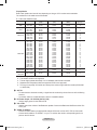
Display Modes
Both screen position and size will vary depending on the type of PC monitor and its resolution.
The resolutions in the table are recommended.
➣
D-Sub and HDMI/DVI Input
Mode
IBM
MAC
VESA CVT
VESA DMT
VESA GTF
Resolution
640 x 350
720 x 400
640 x 480
832 x 624
1152 x 870
720 x 576
1152 x 864
1280 x 720
1280 x 960
1280 x 720
640 x 480
640 x 480
640 x 480
800 x 600
800 x 600
800 x 600
1024 x 768
1024 x 768
1024 x 768
1152 x 864
1280 x 1024
1280 x 1024
1280 x 800
1280 x 800
1280 x 960
1360 x 768
1440 x 900
1440 x 900
1680 x 1050
1280 x 720
1280 x 1024
VESA DMT /
1920 x 1080p
DTV CEA
➣
➣
➣
➣
➣
Horizontal Frequency
(KHz)
31.469
31.469
35.000
49.726
68.681
35.910
53.783
44.772
75.231
56.456
31.469
37.861
37.500
37.879
48.077
46.875
48.363
56.476
60.023
67.500
63.981
79.976
49.702
62.795
60.000
47.712
55.935
70.635
65.290
52.500
74.620
Vertical Frequency
(Hz)
70.086
70.087
66.667
74.551
75.062
59.950
59.959
59.855
74.857
74.777
59.940
72.809
75.000
60.317
72.188
75.000
60.004
70.069
75.029
75.000
60.020
75.025
59.810
74.934
60.000
60.015
59.887
74.984
59.954
70.000
70.000
Pixel Clock Frequency
(MHz)
25.175
28.322
30.240
57.284
100.000
32.750
81.750
74.500
130.000
95.750
25.175
31.500
31.500
40.000
50.000
49.500
65.000
75.000
78.750
108.000
108.000
135.000
83.500
106.500
108.000
85.500
106.500
136.750
146.250
89.040
128.943
Sync Polarity
(H / V)
+/-/+
-/-/-/-/+
-/+
-/+
-/+
-/+
-/-/-/+/+
+/+
+/+
-/-/+/+
+/+
+/+
+/+
-/+
-/+
+/+
+/+
-/+
-/+
-/+
-/+
-/-
67.500
60.000
148.500
+/+
When using an HDMI / DVI cable connection, you must use the HDMI (DVI) IN 1 jack.
The interlace mode is not supported.
The set might operate abnormally if a non-standard video format is selected.
Separate and Composite modes are supported. SOG is not supported.
Too long or low quality VGA cable can cause picture noise at high resolution modes (1920x1080
or 1600x1200).
3 ANT IN
- To view television channels correctly, a signal must be received by the set from one of the following
sources:
- An outdoor antenna / A cable television network / A satellite network
4 DC Power Output - 5V DC/2.5A (12V DC/1.5A)
- Used to supply power for the SBB or STB.
5 VOL-CTRL
- Used to control the volume of the Bathroom speaker. Connect the Bathroom Wall Box and the VOLCTRL port.
6 VIDEO / R-AUDIO-L
- Connect a VIDEO cable to an appropriate external A/V device such as VCR, DVD or Camcorder.
- Connect audio cables to "R-AUDIO-L" on your TV and the other ends to corresponding audio out
jacks on the A/V device.
English - BN68-02157K-x0-Eng.indd 5
2009-04-16 ¿ÀÈÄ 5:03:15
7 Kensington Lock
- The Kensington lock (optional) is a device used to physically fix the system when used in a public
place.
- If you want to use a locking device, contact the dealer where you purchased the TV.
- The location of the Kensington Lock may be different depending on its model
8 RJP
- This port is an RJP (Remote Jack Pack) communication port that enables connecting different
devices to additional module so as to improve device use convenience.
9 HP-ID
- Enables to identify whether a headphone jack is inserted into the additionally created head phone
box.
0 DATA
- Used to support data communication between the TV and the SBB.
- The TV jack type is RJ-12.
! VARIABLE AUDIO OUT
- Used for the audio output to the Bathroom speaker. Connect the Bathroom Wall Box and the
Variable port (RCA).
@ CLONING/SERVICE
- USB Cloning (refer to page 22)
- Service connector
- Hotel Logo download
# COMPONENT IN
- Connect component video cables (optional) to the component jacks ("PR", "PB", "Y") on the rear of
your TV and the other ends to corresponding component video out jacks on the DVD.
- If you wish to connect both the Set-Top Box and DVD, you should connect the Set-Top Box to the
DVD and connect the DVD to the component jacks ("PR", "PB", "Y") on your TV.
- The PR, PB and Y jacks on your component devices (DVD) are sometimes labeled Y, B-Y and R-Y
or Y, Cb and Cr.
- Connect RCA audio cables (optional) to "R - AUDIO - L" on the rear of the TV set and the other
ends to corresponding audio out jacks on the DVD.
$ EXT
Connector
EXT
Video
O
Input
Audio (L/R)
O
Output
Video + Audio (L/R)
Only TV or DTV output is available.
RGB
O
-Inputs or outputs for external devices, such as VCR, DVD, video game device or video disc players.
% Headphones jack
- Headphones may be connected to the headphone jack on your TV. While the headphones are
connected, the sound from the built-in speakers will be disabled.
English - BN68-02157K-x0-Eng.indd 6
2009-04-16 ¿ÀÈÄ 5:03:15
Viewing the Remote Control
1POWER
Turns the TV on and off.
2NUMERIC BUTTONS
Press to change the
channel.
^SOURCE
Press to display and select
the available video sources.
&FAV.CH
Press to switch to your
favorite channels.
3ALARM
Enter the hour you want the *MENU
Displays the main on-screen
TV to turn on.
menu.
4 (MUTE)
Press to temporarily cut off (RETURN
the sound.
Returns to the previous
menu.
5+ = Press to increase or
) UP▲ / DOWN▼ / LEFT◄ / decrease the volume.
RIGHT► / ENTER
Use to select on-screen
6CH LIST
menu items and change
Used to display Channel
menu values.
Lists on the screen.
a EXIT
7 TOOLS
Press to exit the menu.
Use to quickly select
frequently used functions.
b P.SIZE
Picture Mode / Sound Mode / Picture size selection.
Sleep Timer / Energy Saving
cSRS
8 INFO
Selects SRS TruSurround
HD mode.
Press to display information
on the TV screen.
dSUBT.
9COLOR BUTTONS
Digital subtitle display.
Use these buttons in the
e GUIDE
Channel list, etc.
Electronic Programme
Guide (EPG) display.
!DUAL
Sound effect selection.
@Use these buttons in the
DMA and Anynet+ modes.
: This remote can be
(
used to control recording on
Samsung recorders with the
Anynet+ feature.)
#TV
Selects the TV mode
directly.
$PRE-CH
Tunes to the previous
channel.
% < P >
Press to change channels.
Teletext Functions
6 Teletext store
7 Teletext size selection
8 Teletext reveal
9 Fastext topic selection
0Alternately select Teletext,
Double, or Mix.
# Exit from the teletext display
$ Teletext sub page
% P>: Teletext next page
P<: Teletext previous page
^Teletext mode selection
(LIST/FLOF)
* Teletext index
(Teletext hold
a Teletext cancel
➣ The performance of the remote control may be affected by bright light.
English - BN68-02157K-x0-Eng.indd 7
2009-04-16 ¿ÀÈÄ 5:03:17
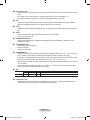
Using the Anti-Theft Kensington Lock
The Kensington lock is a device used to physically fix the system when using it in a public
place. The appearance and locking method may differ from the illustration depending on the
manufacturer. Refer to the manual provided with the Kensington lock for proper use. The locking
device has to be purchased separately.
1. Insert the locking device into the Kensington slot
on the LCD TV (Figure 1), and turn it in the locking
direction (Figure 2).
2. Connect the Kensington lock cable.
3. Fix the Kensington lock to a desk or a heavy
stationary object.
➣ The location of the Kensington Lock may be
different depending on its model.
Cable
Figure 2
Figure 1
<Optional>
English - BN68-02157K-x0-Eng.indd 8
2009-04-16 ¿ÀÈÄ 5:03:18
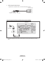
Connecting the TV with STB (SBB)
TV Rear Panel
Hotel Server
STB(Set Top Box)
or SBB(Set Back Box)
2 Dc Cable
1 Data Cable
1. Connect the [DATA] jack of the TV to the [ETH MODEM] jack of the STB(SBB) with the Data cable.
➣ Use data communication.
2. Connect the [Class 2 Wiring-5V DC/2.5A (12V DC/1.5A)] jack of the TV to the [DC-POWER] jack of
the STB (SBB) with the DC cable.
➣ The supported jack type differs depending on the STB (SBB) model.
➣ TV Jack Type: 6.5 Ø DC Power Jack
➣ Some STB (SBB) devices are not compatible with the data cable supplied with the TV.
English - BN68-02157K-x0-Eng.indd 9
2009-04-16 ¿ÀÈÄ 5:03:19
Warning
When you use the DC power output jack, you have to check the standard output power of
STB(SBB) and you should use the DC power within the standard output(Class 2 Wiring-5V
DC/2.5A (12V DC/1.5A).
- For 5V SBB, SBB load current must not exceed 2.5A.
- For 12V SBB, SBB load current must not exceed 1.5A.
- The initial output is 5V.
- For 12V SBB, you have to change the output voltage to 12V in order to use the power.
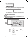
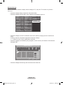
Changing the Output Voltage
1. Press the POWER button.
➣ The TV is powered on.
2. Press the following remote control
buttons in order.
➣ The Hotel Option menu appears.
Hotel Mode
SI Vendor
Power On Channel
On
Samsung
1
Sub AMP Volume
Sub AMP Mode
13
Energy Saving
2
DC Power Output
Logo Time
Manual
Clone : TV to USB
Time Format
12 Hour
Clone : USB to TV
Power On Source
ATV
Power On Volume
10
PMOLED Test
Min Volume
0
PMOLED Mormal Dimming
3
Max Volume
100
PMOLED StandBy Dimming
2
Panel Button Lock
Off
Audio Loop In
Music Mode (AV)
Off
Clone Hotal Menu
Music Mode (PC)
Off
Menu Display
Off
Off
5 Voits
Welcome Message
Off
Interactive
On
Off
Off
Music Mode (Comp)
Hotel Logo
3. Press the ▲ or ▼ button to select
Off
Music Mode Backlight
Hotel Logo DL
"DC Power Output".
1
5 sec
Logo Display Time
RJP Prlorlty(AV)
2
Press the ◄ or ►button to select
RJP Prlorlty(PC)
Powe r On Option Lsst Option
3
Off
RJP Prlorlty(HDML)
Auto PC
"12V" or "5V".
4. Remove the power cord then plug it
back in again.
➣ The voltage change is applied when you turn the TV on again after changing the
Interactive mode Option setting.
English - 10
BN68-02157K-x0-Eng.indd 10
2009-04-16 ¿ÀÈÄ 5:03:19
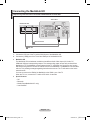
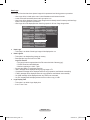
Connecting the Bathroom Speakers
You can connect the Bathroom Speakers in the following method.
Connecting through the Variable Output (available without an external amplifier)
TV Rear Panel
Volume Control Box
VOL +
VOL -
Speaker
+
2
1
1. Connect the VARIABLE AUDIO port of the TV to the Bathroom Wall Speakers of the hotel.
Signal wire : Speaker +
Shield wire : Speaker -
2. Connect the [VOL-CTRL] jack of the TV to the Volume Control Box Switch port of the Bathroom Wall
of the hotel.
➣ The maximum speaker output is 4W, 8Ω.
♦
Installing the Volume Control
- If you configure the Volume Control Box as shown in the figure, you can control the volume of
bathroom speakers.
- The jack that is connected from the Volume Control Box to the TV is a 3.5mm normal Phone jack.
- Volume Control Box switch consists of Tact switch.
➣ Setting the Sub AMP Mode
- 0: Turns the Sub AMP function off (PWM off).
- 1: Determines the Sub volume according to the main volume control. That is, the sub volume is
determined according to the Power On Volume, the Min Volume, and the Max Volume values of
the Hotel Mode.
- 2: Determines the volume according to the bathroom control panel setting.
English - 11
BN68-02157K-x0-Eng.indd 11
2009-04-16 ¿ÀÈÄ 5:03:20
♦
Variable Output Port Specifications
- Speaker Wire: Use speaker cable no more than 82 feet (25m) in length.
Volume Control Box
VOL +
1
3
2
VOL - DOWN
( White 1 )
VOL - UP
( Black /Red 2 )
VOL -
GND
( Shield Wire 3 )
Connect through the Fixed Output (available without an external amplifier)
TV Rear Panel
+
Audio Amplifier
AUDIO IN
1 Stereo cable
1. Connect the AUDIO OUT port of the TV and the Audio In port of the audio amplifier with a stereo
cable.
English - 12
BN68-02157K-x0-Eng.indd 12
2009-04-16 ¿ÀÈÄ 5:03:20
Connecting the MediaHub HD
Output of any external source connected to MediaHub HD on hotel desk.
TV Rear Panel
MediaHub HD Rear
1 RS-232 Data Cable
2 HDMI cable
1. Connect the RJP port of the TV and the RS/232 port of the MediaHub HD.
2. Connect the [HDMI] port of the TV and the HDMI port of the MediaHub HD.
♦
MediaHub HD
The MediaHub HD is a hardware module that has different Audio Video inputs (A/V, Audio, PC,
HDMI and USB) and corresponding outputs. The corresponding output sources are connected from
MediaHub to TV. The MediaHub communicates with the TV via RS232. Hot Plug & Play is a function
that allows hotel guests to connect an external source to the MediaHub. The MediaHub communicates
with the TV by sending messages regarding Active/Inactive sources. The TV will switch to the Active
external source.
You have to connect the HDMI of the MediaHub to the HDMI 1 port of the TV.
When the TV is on, connect the TV and the RJP within 10 seconds.
♦
Special features
-
PIP
Bluetooth
Media Player(MediaHub HD+ only)
Auto Detection
English - 13
BN68-02157K-x0-Eng.indd 13
2009-04-16 ¿ÀÈÄ 5:03:21
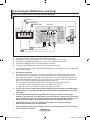
Connecting the RJP(Remote Jack Pack)
Output of any external source connected to RJP on hotel desk.
5 Video Cable
3 Video / Audio Cable
1 RS-232 Data Cable
TV Rear Panel
TV Side Panel
RJP Rear
HDMI IN2
2 D-sub / PC Audio cable
4 HDMI cable
1.
2.
3.
4.
5.
Connect the RJP port of the TV and the RS/232 port of the RJP.
Connect the PC IN [PC] / [AUDIO] port of the TV to the PC/AUDIO port of the RJP.
Connect the AV IN [VIDEO]/[R-AUDIO-L] port of the TV to the RCA port of the RJP.
Connect the [HDMI] port of the TV and the HDMI port of the RJP.
Connect the AV IN[VIDEO] port of the TV to the S-Video port of the RJP.
➣ The RJP (Remote Jack Pack) compatible with this Samsung TV is TeleAdapt TA-7610, TA-7650 (HD)
and TA-7660 (HD Plus).
♦
RJP (Remote Jack Pack)
RJP stands for Remote Jack Pack. The RJP is a hardware module that has different Audio Video
inputs (A/V, Audio, PC and HDMI) and corresponding outputs. The corresponding output sources
are connected from RJP to TV. The RJP communicates with the TV via RS232. Hot Plug & Play is a
function that allows hotel guests to connect an external source to the RJP. The RJP communicates
with the TV by sending messages regarding Active/Inactive sources.
The TV will switch to the Active external source according to the priority set by the User.
➣ You have to connect the HDMI of the RJP to the HDMI 1 port of the TV.
➣ When the TV is on, connect the TV and the RJP within 10 seconds.
♦
The RJP can be returned to the factory default settings by pressing the A/V and HDMI buttons
simultaneously for 10 seconds. All LEDs blink 5 times to Acknowledge that the rest has been
performed.
♦
The RJP will automatically turn off any LEDs after 5 minutes to avoid unnecessary light
pollution in the hotel room. The LEDs that were turned off will turn on again if the guest touches
any of the buttons and the 5 minute timer will restart. If the guest then touches another source
button, the TV will change to the selected source and the corresponding LED will be lit.
♦
After an RJP Reset or a TV Power OFF/ON, it takes approx. 10 seconds to establish
communications between the TV and the RJP.
♦
The following table shows the approximate time in seconds to switch from the TV to the input
source, based on the priority.
English - 14
BN68-02157K-x0-Eng.indd 14
2009-04-16 ¿ÀÈÄ 5:03:22
➣ Scenario 1: When no inputs are connected.
Source
To Connect
AV
2 Sec
PC
0.7 Sec
HDMI
3.9 Sec
➣ Scenario 2: When two or more inputs are connected and an Input source is disconnected and
then reconnected.
Source
Disconnect
To Connect
Total
AV
4.5 Sec
2 Sec
6.5 Sec
PC
0.7 sec
0.7 Sec
1.4 Sec
HDMI
3.9 Sec
3.9 Sec
7.8 Sec
➣ E.g. If the RJP has all its live sources AV, PC and HDMI connected, AV is viewed as the highest
priority. If the RJP is in HDMI mode, and a guest removes and reconnects the AV, the minimum
time required to switch to the AV is 6.5 seconds.
♦
To connect audio (Ipod or Mp3), Music mode should be ON and Jack Ident detect should be OFF.
♦
A/V, PC and HDMI input sources are supported.
Audio Loop In
An additionally created Headphone Box can be installed on a bed or business desk so that users can use
it conveniently. The installation procedures are given below. (Not available for 19/22 inch model.)
♦ Detailed Drawing of the Headphone Box
TV Rear Panel
Headphone Box
IN 1
Headphone
Shield wire
Red Wire
(Audio-R)
Whitewire
(Audio-L)
Shield wire
TV
Headphones jack
Red Wire + White wire
TV HP-ID jack
English - 15
BN68-02157K-x0-Eng.indd 15
2009-04-16 ¿ÀÈÄ 5:03:23
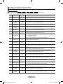
Setting the Hotel Option Data
Stand-alone mode
To Enter: P
ress the
To Exit from this menu : power off and turn on again.
buttons in order.
No
Item
Initial Value
Description
1
Hotel Mode
On
Hotel mode(Stand alone) on/off
2
SI Vendor
Off
Select the SI Vendor
3
Power On
Channel
1
4
Power on
source
ATV
5
Power On
Volume
10
TV will switch on with this Volume Level
6
Min Volume
0
Minimum Volume Level setting user can set
7
Max Volume
100
Maximum Volume Level setting user can set
TV will switch on to this particular Channel
Select the Input source when TV is turned on initially.
8
Panel Button
Lock
Off
Front panel(Local key) operation on/off
- Off : Unlock All panel key
- On : Lock All panel key
- Power : Lock All panel key except Power panel key
9
Pic Menu Lock
Off
Enable or disable Picture Menu
10
Video Mute Ch
1 (Off)
To select Channels not displaying(doing video mute) for example(Radio
channel), If 1 is ON, channel 1 display only black picture.
11
Video Mute Ch
On/Off
Off
To select Channels not displaying(doing video mute) for example(Radio
channel), If 1 is ON, channel 1 display only black picture.
12
Music Mode(AV)
Off
To get music output from mp3/audio player in AV Input Source.
Audio enabled, video disabled in this mode
13
Music
Mode(PC)
Off
To get music output from mp3/audio player in PC Input Source.
Audio enabled, video disabled in this mode
14
Music
Mode(Comp)
Off
To get music output from mp3/audio player in Component Input Source.
Audio enabled, video disabled in this mode
15
Music Mode
Backlight
Off
Backlight On/Off option in Music mode to save energy
16
RJP Priority(AV)
1
If the jack priority is set, the corresponding source is automatically set
when a jack is inserted according to the jack priority.
17
RJP Priority(PC)
2
If the jack priority is set, the corresponding source is automatically set
when a jack is inserted according to the jack priority.
18
RJP
Priority(HDMI)
3
If the jack priority is set, the corresponding source is automatically set
when a jack is inserted according to the jack priority.
19
RJP HDMI
Option
HDMI1
20
Sub AMP
volume
13
Select RJP HDMI Source (HDMI1/HDMI2)
Sub AMP Volume level at power on initial condition.
English - 16
BN68-02157K-x0-Eng.indd 16
2009-04-16 ¿ÀÈÄ 5:03:23
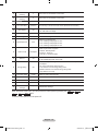
21
Sub AMP mode
2
Determines the Sub AMP operation mode.
- 0: Turns the Sub AMP function off (PWM off).
- 1: Determines the Sub volume according to the main volume
control. That is, the sub volume is determined according to the
Power On Volume, the Min Volume, and the Max
- 2: Determines the volume according to the bathroom control panel
setting.
22
Local time
Manual
Selection of the way to update clock data
- Manual: Use clock data from DVB channel or manual clock setting
when the TV is in the stand-alone mode
- TTX: manual clock setting (with updating from TTX data)
23
Time Format
12hour
Select time expression method(12H/24H)
Reset AC power after setting this option
24
PMOLED Test
Off
This function is not available on this model.
25
PMOLED
Normal
Dimming
3
This function is not available on this model.
26
PMOLED
StandBy
Dimming
2
This function is not available on this model.
27
Audio Loop In
Off
28
Clone Hotel
Menu
Standalone
29
Menu display
Off
- On : Main Menu display
- Off : Main Menu No display
30
Hotel Logo
Off
Select Hotel Logo
31
Hotel Logo DL
Download Hotel Logo from USB to TV
32
Logo Display
Time
5 sec
Selection of the logo display time
- 3 sec: Hotel logo is displayed for 3sec.
- 5 sec: Hotel logo is displayed for 5sec.
- 7 sec: Hotel logo is displayed for 7sec.
33
Power On Opt
Last Option
34
Auto PC
Off
While TV is in power on state, if PC source is connected to TV,
TV will automatically switch to PC mode.
This feature adjusts the brightness of the TV in order to reduce power
consumption.
- Off: Turns off the energy saving function.
- Low: Sets the TV to low energy saving mode.
- Medium: Sets the TV to medium energy saving mode.
- High: Sets the TV to high
Audio loop identification or H.P identification selection
The interactive or stand alone Hotel TV options in the OSD when
pressing the Hotel key on the clone remote control. (Stand Alone/
Interactive)
Power On(AC Power On) Option
- STN-BY : Stand-By Mode
- Power On : Power On
- LAST OPT : Last Power State
35
Energy Saving
Off
36
Clone :
TV to USB
-
USB Clone : TV → USB
37
Clone :
USB to TV
-
USB Clone : USB → TV
38
Pan Euro
MHEG
Off
39
Welcome
message
Off
40
Edit Welcome
message
Display Welcome Message
Edit Welcome Message
English - 17
BN68-02157K-x0-Eng.indd 17
2009-04-16 ¿ÀÈÄ 5:03:23
Interactive Mode
buttons in order, in normal operation
To Enter: Press the
state.
To Exit from this menu : Power Off and Turn On again.(Press Power button with general SAMSUNG remocon)
No
Item
Initial Value
Description
1
Hotel Mode
On
2
SI Vendor
Samsung
Hotel mode(Interactive) on/off
3
Power On Channel
1
4
Power on source
ATV
5
Power On Volume
10
TV will switch on with this Volume Level
6
Min Volume
0
Minimum Volume Level setting user can set
7
Max Volume
100
Maximum Volume Level setting user can set
Select the SI Vendor
TV will switch on to this particular Channel
Select the Input source when TV is turned on initially.
8
Panel Button Lock
Off
Front panel(Local key) operation on/off
- Off : Unlock All panel key
- On : Lock All panel key
- Power : Lock All panel key except Power panel key
9
Music Mode(AV)
Off
To get music output from mp3/audio player in AV Input Source.
TV sound is generated in only black picture whether being Video Singal or not.
10
Music Mode(PC)
Off
To get music output from mp3/audio player in AV Input Source.
TV sound is generated in only black picture whether being Video Singal or not.
11
Music Mode(Comp)
Off
To get music output from mp3/audio player in PC Input Source.
TV sound is generated in only black picture whether being Video Singal or not.
12 Music Mode Backlight
On
Backlight On/Off option in Music mode to save energy
13
RJP Priority(AV)
1
If the jack priority is set, the corresponding source is automatically set when
a jack is inserted according to the jack priority.
14
RJP Priority(PC)
2
If the jack priority is set, the corresponding source is automatically set when
a jack is inserted according to the jack priority.
15
RJP Priority(HDMI)
3
If the jack priority is set, the corresponding source is automatically set when
a jack is inserted according to the jack priority.
16
RJP HDMI Option
HDMI1
17
Sub AMP volume
13
Sub AMP Volume level at power on initial condition.
2
Determines the Sub AMP operation mode.
- 0: Turns the Sub AMP function off (PWM off).
- 1: Determines the Sub volume according to the main volume control.
That is, the sub volume is determined according to the Power On
Volume, the Min Volume, and the Max
18
Sub AMP mode
Select RJP HDMI Source (HDMI1/HDMI2)
19
Local time
Manual
Selection of the way to update clock data
- Auto: Use clock data from server when the TV is in the interactive
mode
- Manual: Use clock data from DVB channel or manual clock setting
when the TV is in the stand-alone mode
- TTX: manual clock setting (with updating from TTX data)
20
Time Format
12hour
Select time expression method(12H/24H)
Reset AC power after setting this option
21
PMOLED Test
Off
This function is not available on this model.
English - 18
BN68-02157K-x0-Eng.indd 18
2009-04-16 ¿ÀÈÄ 5:03:23
22
PMOLED Normal
Dimming
3
This function is not available on this model.
23
PMOLED StandBy
Dimming
2
This function is not available on this model.
24
Audio Loop In
Off
25
Clone Hotel Menu
Interactive
26
Menu display
Off
- On : Main Menu display
- Off : Main Menu No display
27
Hotel Logo
Off
Select Hotel Logo
28
Hotel Logo DL
-
29
Logo Display Time
5 sec
Audio loop identification or H.P identification selection
The interactive or stand alone Hotel TV options in the OSD when pressing
the Hotel key on the clone remote control. (Stand Alone/ Interactive)
Download Hotel Logo from USB to TV
Select the logo display time
- 3 sec: Hotel logo is displayed for 3sec.
- 5 sec: Hotel logo is displayed for 5sec.
- 7 sec: Hotel logo is displayed for 7sec.
Power On(AC Power On) Option
- STN-BY : Stand-By Mode
- Power On : Power On
- LAST OPT : Last Power State
30
Power On Opt
Last Option
31
Auto PC
Off
While TV is in power on state, if PC source is connected to TV,
TV will automatically switch to PC mode.
This feature adjusts the brightness of the TV in order to reduce power
consumption.
- Off: Turns off the energy saving function.
- Low: Sets the TV to low energy saving mode.
- Medium: Sets the TV to medium energy saving mode.
- High: Sets the TV to high
32
Energy Saving
Off
33
DC Power Output
5 Volts
34
Clone : TV to USB
-
35
Clone : USB to TV
-
36
Welcome message
Off
37
Edit Welcome
message
-
Select DC power output (5V/12V)
USB Clone : TV → USB
USB Clone : USB → TV
Display Welcome Message
Edit Welcome Message
When Interactive mode is On, you cannot enter the Hotel Options by pressing the
1
9
Enter button.
To exit the Hotel Options, turn the power off.
Mute
1
English - 19
BN68-02157K-x0-Eng.indd 19
2009-04-16 ¿ÀÈÄ 5:03:24
Welcome Message
Welcome message is a feature to display custom message on TV, every time TV is turned on by Guest in
Hotel room.
- Welcome message settings are placed in Hotel Option Menu.
- Welcome message should be ON in order to display the message on power on.
Hotel Mode
Sub AMP Volume
On
SI Vendor
13
Energy Saving
2
DC Power Output
Manual
Clone : TV to USB
Sub AMP Mode
Samsung
Power On Channel
1
Off
5 Voits
Logo Time
Time Format
12 Hour
Clone : USB to TV
Power On Source
ATV
Power On Volume
10
PMOLED Test
Min Volume
0
PMOLED Mormal Dimming
Max Volume
100
PMOLED StandBy Dimming
Panel Button Lock
Off
Audio Loop In
Music Mode (AV)
Off
Clone Hotal Menu
Music Mode (PC)
Off
Menu Display
On
Music Mode (Comp)
Off
Hotel Logo
Off
Music Mode Backlight
Off
Hotel Logo DL
Welcome Message
Off
On
Edit Welcome Message
3
2
Off
Interactive
RJP Prlorlty(AV)
1
Logo Display Time
5 sec
RJP Prlorlty(PC)
2
Powe r On Option
Lsst Option
RJP Prlorlty(HDML)
3
Auto PC
Off
- Welcome message can be of 25 characters and it can be edited by changing its text in Hotel Service
menu.
- Following is the list of characters supported for Welcome message:
➣ In letters from A to Z only in capital letters is allowed.
- Welcome message can be edited by using navigation, color & enter key of a Remote in “Edit Welcome
Message” OSD.
Edit Welcome Message
W
E
L
R
C
H
O
O
M
T
E
E
T
L
O
O
U
_
A
B
C
D
E
F
H
I
J
K
L
M
N
O
P
Q
R
S
T
U
V
W
X
Y
Z
G
Move Left
Move Right
Black
Done
Move Enter
Return
- Welcome message and hotel logo cannot be active at the same time.
English - 20
BN68-02157K-x0-Eng.indd 20
2009-04-16 ¿ÀÈÄ 5:03:24
Hotel Logo
Hotel Logo is a function that shows picture image which represents hotel during power on procedure.
- Hotel Logo will be in hotel option menu in both Standalone and Interactive mode.
- Lower menus will be enabled when hotel Logo option is on.
- Hotel Logo will be displayed if there is logo image which is already stored in memory and hotel logo
option is on during power on procedure.
- Hotel Logo will not be displayed when Hotel Logo option is off even if logo image exists.
Hotel Mode
SI Vendor
Power On Channel
On
Samsung
1
Sub AMP Volume
13
Energy Saving
Sub AMP Mode
2
DC Power Output
Logo Time
Manual
Clone : TV to USB
Time Format
12 Hour
Clone : USB to TV
Power On Source
ATV
Power On Volume
10
PMOLED Test
Min Volume
0
PMOLED Mormal Dimming
Max Volume
100
PMOLED StandBy Dimming
Panel Button Lock
Off
Audio Loop In
Music Mode (AV)
Off
3
Off
5 Voits
Welcome Message
Off
Edit Welcome Message
2
Off
Off
Clone Hotal Menu
Music Mode (PC)
Off
Menu Display
On
Music Mode (Comp)
Off
Hotel Logo
On
Music Mode Backlight
Off
Hotel Logo DL
RJP Prlorlty(AV)
1
Logo Display Time
RJP Prlorlty(PC)
2
Powe r On Opt
RJP Prlorlty(HDML)
3
Auto PC
Interactive
5 sec
Last Option
Off
♦
Hotel Logo
♦
- This option is to decide if hotel logo image will be displayed or not.
Hotel Logo DL
♦
- This option is to download logo image to memory.
- Download the Logo File from PC to USB.
Logo File Format
- Only jpeg format is supported and the File name should be “Samsung.jpg”.
- File size must be under 256Kbytes.
- Maximum resolution is 1920 * 1080.
- Connect the USB to TV and press Enter key.
- “Wait” message will be displayed during copying image to TV.
- “Completed” message will be displayed when the copy operation was finished successfully.
- “Failed” message will be displayed when the copy operation was finished unsuccessfully.
- “No USB” message will be displayed when any USB is not connected.
- “No File” message will be displayed when there is no file to copy in USB.
Logo Display Time
- This option is to decide Logo display time.
- 3 sec / 5 sec / 7sec
English - 21
BN68-02157K-x0-Eng.indd 21
2009-04-16 ¿ÀÈÄ 5:03:24
USB Cloning
USB Cloning is a function to download user configured settings (Picture, Sound, Input, Channel,
Setup, and Hotel Setup) from one TV set and upload the same to other TV sets.
All the user-defined settings from the TV (Master Set) can be copied to the USB device.
USB Cloning is in hotel option menu in both Standalone and Interactive mode.
♦
Cloning from TV to USB
It is an operation to copy the stored data from the specific area on the EEPROM
from the TV set to the USB device.
1.Insert a USB drive into the USB port on the rear of the TV.
2.Enter the hotel menu by pressing this buttons in order.
- Interactive mode : INFO → MENU → 0 → 1 → EXIT
- Standalone mode : MUTE → 1 → 1 → 9 → ENTER
3.Press the ▲ or ▼ button to select “Clone: TV to USB”, then press the ENTER
button.
4.The message “Clone: TV to USB” is displayed, then press the ENTER button.
5.You can Make sure USB cloning behavior.
- “In Progress” : during copying data to USB.
- “Completed” : copy operation was finished successfully.
- “Failed” : copy operation was not finished successfully.
- “No USB” : any USB is not connected.
♦
Energy Saving
DC Power Output
Off
5 Volts
Clone: TV to USB
Clone:USB to TV
Welcome Message
Off
Edit Welcome Message
Cloning from USB to TV
It is an operation to download the stored data in USB device to TV set.
1.Insert a USB drive into the USB port on the rear of the TV.
2.Enter the hotel menu by pressing this buttons in order.
- Interactive mode : INFO → MENU → 0 → 1 → EXIT
- Standalone mode : MUTE → 1 → 1 → 9 → ENTER
3.Press the ▲ or ▼ button to select “Clone: USB to TV”, then press the ENTER
Energy Saving
DC Power Output
button.
Clone: TV to USB
4.The message “Clone: USB to TV” is displayed, then press the ENTER button.
Clone: USB to TV
Welcome Message
5.You can Make sure USB cloning behavior.
Edit Welcome Message
- “In Progress” : during copying data to TV.
- “Completed” : copy operation was finished successfully.
- “Failed” : copy operation was not finished successfully.
- “No USB” : any USB is not connected.
- “No File” : there is no file to copy in USB.
➣ The operation to copy from USB to TV can be executed by pressing Enter key for 5 seconds.
Off
5 Volts
Off
For fast instant cloning during installation!
Insert USB key with master settings from first TV and press Enter key for 5 seconds.
English - 22
BN68-02157K-x0-Eng.indd 22
2009-04-16 ¿ÀÈÄ 5:03:25
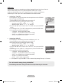
Hotel Plug & Play
Hotel Plug & Play is a function that automatically performs the Hotel mode selection, Country Setup, Clock
Setup and Picture mode Setup once.
- Hotel Plug & Play is available only one time when power is first turned ON.
- After setting up first TV and Clone TV to USB
- Next TV only needs to exit Hotel Plug & Play, connect USB, then Clone USB to TV
♦
UI Scenario
If exit is selected
Hotel Plug & Play
Easy Set Up
Ok
After 3 sec
Standalone mode is set.
Exit
Hotel Plug & Play
Select Interactive for Interactive Hotel Menu Settings.
Interactive
TV will enter the RF
mode.
Interactive
Hotel Option Menu
Standalone
Press Power OFF
to exit.
If Standalone is
selected
Hotel Plug & Play
Hotel Plug & Play
You can set the menu language.
Menu Language
: English ►
Hotel Plug & Play
Select Country.
Country
Select the Antenna source to memorize.
: United Kingdom ►
Exit
Exit
Hotel Plug & Play
Standalone
Hotel Option Menu
Start
◄►Move
after
30 sec
Exit
Menu
Select Clock Mode.
Clock Mode
Standard
◄►Move
Start
Cable
Hotel Plug & Play
Select this for Dynamic Picture.
Dynamic
Air
Exit
: Auto
Exit
►
Menu
Press Power OFF
to exit.
English - 23
BN68-02157K-x0-Eng.indd 23
2009-04-16 ¿ÀÈÄ 5:03:25
Multi Code Remocon
Multi Code Remocon is a special transmitter which is designed to control each TVs with one remote.
This function is useful where there is more than one TV in one location like hospital
Set ID number will be displayed in source osd.
It is possible to support up to 10 different remote key transmission for multi code.
Initial ID code which each TV has is “0”.
- ID code could be set and reset in Analog TV mode or PC mode.
(not available in TTX channel or DTV channel)
- ID code could be from 0 to 9.
- Press Blue Key for over 3 seconds and the digit key a user wants to set.
- Set ID OSD will be displayed in central position.
- The following words will be displayed. “Remote control code is set to x. If you want to change Remote
control code. Enter the digit you want to change.” (x is the digit number)
This OSD will be kept displaying until exit key is input.
Remote control code is set to 0. If you want
to change Remote control code, enter the digit
you want to change.
- For example, TV and Remote will be set ID code #1 if user presses #1.
The following words will be displayed.“Remote control code is changed to 1”
Then TV can be controlled by only remote which has same ID code with TV’s.
- If ID code does not match between remote and TV, the following words will be displayed.
“ TV ID x”(x is the TV’s ID)
- To reset ID code, press Yellow key for over 3 seconds. ID code of both TV and Remote will be reset to “0”.
“Remote control code is set to 0.” will be displayed.
English - 24
BN68-02157K-x0-Eng.indd 24
2009-04-16 ¿ÀÈÄ 5:03:25
Setting the Time
♦
The time is entered
- Press the remote control button to select "Clock set"
and set up the time.
“Menu” → “Setup” → “Time” → “Clock” →
“Clock Set”
♦
Clock
Clock Mode
: Manual
Clock Set
TV
Setting the Interactive Mode Time
- If the Hotel System transmits time information, the
time is set automatically.
- If the Hotel System does not transmit time information,
the time cannot be displayed.
ClockEnter
Set
Move
►
Return
Clock Set
Day
u
Month
Year
01
01
01
Hour
Minute
01
01
d
Move
U
Adjust
Enter
Return
English - 25
BN68-02157K-x0-Eng.indd 25
2009-04-16 ¿ÀÈÄ 5:03:25
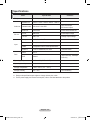
Specifications
Items
TV System
Audio out
DC out
Input
Data
Specification
Comment
DVB-T/C, PAL, SECAM, NT4.43
Speaker out
32inch / 37inch / 40inch / 46inch : 10W x 2
Variable Audio
4W mono 8 ohm SPK'
RCA Jack output
BTL Sound output
Audio out
500mVrms
Phone Jack, Monitor out
5V out
Max 2.5A
Initial output Voltage
12V out
Max 1.5A
Change output voltage
Component
Y, Pb, Pr, Audio-L/R
PC
D-sub, Audio-L/R
HDMI
Compatible with the HDMI Specifications
Antenna
75 ohm Unbalanced, Din Jack
DATA
RJ-12
RJP
RS232
VHF/UHF/CATV
Jack Pack Only, TeleAdapt
RJP Only
Operating temperature
10°C ~ 40°C (50°F ~ 104°F)
Operating Humidity
10% ~ 80%
Storage Temperature
-20°C ~ 45°C (-4°F ~ 113°F)
Storage Humidity
5% ~ 95%
non-condensing
non-condensing
➣ Design and specifications are subject to change without prior notice.
➣ For the power supply and Power Consumption, refer to the label attached to the product.
English - 26
BN68-02157K-x0-Eng.indd 26
2009-04-16 ¿ÀÈÄ 5:03:25
This page is intentionally
left blank.
BN68-02157K-x0-Eng.indd 27
2009-04-16 ¿ÀÈÄ 5:03:25
This page is intentionally
left blank.
BN68-02157K-x0-Eng.indd 28
2009-04-16 ¿ÀÈÄ 5:03:25
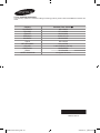
Contact SAMSUNG WORLDWIDE
If you have any questions or comments relating to Samsung products, please contact the SAMSUNG customer care
centre.
Country
AUSTRALIA
FINLAND
FRANCE
GERMANY
HUNGARY
ITALIA
NETHERLANDS
POLAND
PORTUGAL
SPAIN
UNITED KINGDOM
Customer Care Centre
800-112233
0771-400002
0825-022082
01805-471101
0840-985985
800-194194
015-2197000
0-801-B2BSAM (222728)
808-B2BSAM
0902024-010
+44 (0) 845 8414141
BN68-02157K-00
BN68-02157K-x0-Eng.indd 29
2009-04-16 ¿ÀÈÄ 5:03:26


![[LC460_463_467] Euro-Africa-hotel](http://vs1.manualzilla.com/store/data/006789527_1-5fc70cd98184635ab5bbcf80df43a195-150x150.png)