1
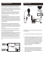
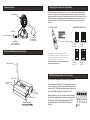
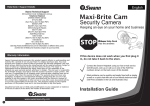
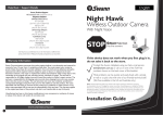
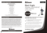
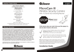
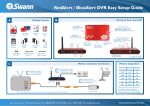
English
Help Desk / Support Details
Swann Technical Support
All Countries E-mail: [email protected]
Telephone Helpdesk
UNITED STATES toll free
1-800-627-2799
1-877-274-3695
(Su, 2pm-10pm US PT)
(M-Th, 6am-10pm US PT)
(F 6am-2pm US PT)
USA Exchange & Repairs
562-777-2551
(M-F, 9am-5pm US PT)
AUSTRALIA toll free
1300 138 324
(M 9am-5pm AUS ET)
(Tu-F 1am-5pm AUS ET)
(Sa 1am-9am AUS ET)
New Zealand toll free
0800 479 266
International
+61 3 8412 4610
Safety Camera Kit
Wireless Camera & Receiver
See http://www.worldtimeserver.com for information on different time zones
and the time in Melbourne Australia compare to your local time.
WARNING: IMPORTANT NOTICE ABOUT CORRECT USE OF POWER ADAPTER
The correct orientation
for the enclosed power
adapter is in a vertical
or floor mount position
L’orientation correcte pour
L’adapteur secteur fourni
est dans une position
verticale ou planchermonte.
La orientacion correcta para
el adaptador electrico incluido
es en posicion vertical o instalado
en el suelo.
12
DC
L
Warranty Information
Swann Communications U.S.A. Inc.
10612 Shoemaker Avenue, Bldg A
Santa Fe Springs, CA 90670 USA
1-800-627-2799
Swann Communications warrants this product against defects in workmanship and material for
a period of one (1) year from it’s original purchase date. You must present your receipt as
proof of date of purchase for warranty validation. Any unit which proves defective during the
stated period will be repaired without charge for parts or labour or replaced at the sole
discretion of Swann. The repair or replacement will be warranted for either ninety days or the
remainder of the original one year warranty period, whichever is longer. The end user is
responsible for all freight charges incurred to send the product to Swann’s repair centres. The
end user is responsible for all shipping costs incurred when shipping from and to any country
other than the country of origin. The warranty does not cover any incidental, accidental or
consequential damages arising from the use of or the inability to use this product. Any costs
associated with the fitting or removal of this product by a tradesman or other person or any
other costs associated with its use are the responsibility of the end user. This warranty applies
to the original purchaser of the product only and is not transferrable to any third party.
Unauthorised end user or third party modifications to any component or evidence of misuse or
abuse of the device will render all warranties void.
4
3
2
1n
o
If this device does not work when you first plug it
in, do not take it back to the store.
Contact the Swann Helpdesk using our fast e-mail service
[email protected] or call us on one of the Toll-Free
numbers shown on the back cover of this booklet.
FCC INFORMATION
This device complies with Part15 of the FCC Rules. Operation is subject to the following two
conditions:
(1) This device may cause harmful interference,
(2) This device must accept any interference received, including interference that may cause
undesired operation.
Changes or modifications not expressly approved by the party responsible for compliance
could void the user’s authority to operate the equipment.
Installation Guide
www.swannsecurity.com
V
Introduction
The Swann Safety Camera Kit allows you to wirelessly transmit pictures and
sound with ease. As the radio waves it uses have a frequency of 2.4GHz, they
can be received within a radius of up to 160ft/50m in open line of sight. The Safety
Camera Kit Receiver works with other Swann wireless cameras to allow you to
have the option of using different frequencies for different locations and conditions
to ensure that you have the best possible image quality for your situation.
Please note: The Swann Safety Camera Kit broadcasts video in the public
domain. The video signal is not encrypted and could potentially be viewed by
anyone with a similar 2.4GHz receiver unit. Please keep this in mind when
positioning and using any wireless camera equipment.
WARNING - IMPORTANT SAFETY INSTRUCTIONS
To reduce fire or shock hazard do not expose the unit or adapters to rain or moisture
Do not handle damaged or leaking Lithium-Ion batteries
Do not use if any of the terminals or wires are exposed
Use only the power adapter that is included in this pack in an upright or vertical position
Any modifications not approved by Swann Communications PTY LTD. may void the user’s
ability to operate this product
Technical Specifications
Safety Camera
Sensor:
Horizontal Resolution:
Auto Electronic Exposure:
Minimum Illumination:
Signal to Noise Ratio:
Board Lens:
View Angle:
Video System:
1/3” Colour CMOS
380 TV lines
1/60 - 1/15000 sec.
1 Lux @ f1.2
>48dB
7
/32” ; 5.6mm
60 degrees
PAL 50Hz (Australia, UK/Europe),
NTSC 60Hz (USA and Canada)
Automatic Exposure / Gain / White balance/IR LED activation
Available Channels:
RF Output Power:
Operating Power:
Size:
Antenna:
Transmitting Range:
Weight:
Operating Temperature:
4 Channels in 2.4Ghz frequency band*
FCC, CE and C-tick compliant
12V DC
1.1”x1.2”x1.1” (28x30x28mm)
Omni-directional
Up to 160ft ~ 50M line of sight
¾oz ~ 20 grams
-10° - 50°C (14° - 122°F)
Package Contents
•
•
•
•
•
•
•
•
Safety Camera with built in 2.4GHz Transmitter and Stand
4 channel 2.4GHz Receiver
Antenna for Receiver
2 x Mains Power Adaptor (1 for use with Camera and 1 for Receiver)
RCA A/V Cable
Manual & Accessories
Focus Tool
Dip Switch Tool
If any of these items are missing, please contact your retailer.
NOTE:
All jurisdictions have specific laws and regulations relating to the use of cameras.
Before using any camera for any purpose, it is the buyer’s responsibility to be
aware of all applicable laws and regulations that prohibit or limit the use of
cameras and to comply with the applicable laws and regulations.
The legality of watching people other than yourself changes from country to
country and even state to state. Contact your local government's privacy
information body or your local Police for more information on what if any
restrictions you may face.
Receiver
Frequency:
Video input/output:
Audio input / output:
Audio Bandwidth:
Operating Power:
Size:
4 Channels in 2.4 Ghz frequency band
1V p - p / 75 ohm
1V / 10kW
50 - 17000 Hz
12V DC
4.7”x3.5”x1” (120 x 90 x 25mm)
*The Safety Camera Kit uses following frequencies for the 4 channels:
Channel 1( 2414MHz), Channel 2 (2432MHz), Channel 3 (2450MHz)
and Channel 4 (2468MHz).
Troubleshooting, hints and tips
Setting up your system
Poor Picture: Realign antennas until image quality improves, slightly adjust the
position of the Camera or Receiver. Change the location of the Camera to allow the
minimum of solid objects such as walls between it and the receiver as illustrated at the
bottom of the page. Try changing to one of the other channels using the instructions on
the previous page and check the signal quality again.
Camera with Stand and Hood
DVR or MONITOR
With RCA Sockets
Lines only: no clear picture: Check to confirm there is no microwave oven or other
2.4GHz equipment operating close by ie; Cordless Telephones, Wireless Baby
Monitors, Wireless LAN equipment etc . Make sure the Receiver is on the correct
channel for the particular camera.
VIDEO AUDIO
OUT
IN
Picture ghosting or interference: Some home appliances such as Wireless LANs,
2.4GHz portable telephones and Microwave ovens operate on or near the 2.4GHz
frequency. If you receive interference from such an appliance, try moving the Camera
or Receiver to location further away from the appliance or in the event of interference
from a Wireless LAN device, try changing the Wireless LAN to a different channel to
improve the signal quality.
Receiver
RCA A/V Cable
CH4
Receiver
Power Adaptor
Camera Power Adaptor
No picture: check the receiver to confirm it is powered and make sure the A/V
connection of the Receiver is not plugged into the Audio Out socket. Make sure the
Receiver is on the correct channel. Check to ensure the camera is plugged in and has
power. Check that the channel on the receiver is the set to the same as the camera
you wish to view.
Red haze over picture: In some cases where the sun shines into the front of the
camera a faint red glow can be seen. Move the camera to a shaded location, or fit a
hood to stop sunlight entering the camera lens directly.
Foreground is dark while background is too bright: If the camera is looking from a
dark area towards a light area in some cases the automatic exposure can find it
difficult to balance the image correctly. Change the location of the camera so that the
point of greatest interest has the largest area of the image (if you want to see the
bright area, move the camera so that almost all of the screen shows this area. If you
want to see the darker area, move the camera so that most of the image shows this
area)
Signal passes
through 3 walls
x
Receiver
CH4
Signal only passes
through 2 walls!
The Camera features an omni-directional antenna which is most effective when used
in the UPRIGHT position.
1)
Connect both the Camera and the Receiver to their respective power adaptors.
2)
Connect the Receiver to the equipment you wish to view the camera on (monitor,
AV TV, VCR, DVR etc) using the supplied RCA A/V-cable. If you have an A/V TV
with RCA sockets you will need to switch the TV to the AV channel to view the
camera. To connect the Receiver to your VCR, you will need to turn the VCR to
the AV Input selection and turn your TV onto the channel you would normally use
to view a tape or movie on your VCR. The AV channel may be activated by a
button on your remote that is marked with this symbol
, or L1 or L2 or
possibly AV, AV1 or AV2. Check the manual of your TV or VCR for more
information on using its AV inputs.
3)
After connecting both the Camera and the Receiver make sure the receiver is
switched to the same channel as the camera. Press the Channel Select button
on the receiver until the LED is lit. Obtain the best picture by adjusting the
position of the Camera and Receiver unit to suit. Try slightly different locations of
either unit for optimum results.
Your home or office
Monitor or TV
VIDEO AUDIO
Camera features
Changing the channel on the camera
The Safety Camera can be switched to any of four frequencies to assist in avoiding
interference. Please see the illustration below for frequency settings. On the power
cable connected to the camera find the small flap covering the two dip switches. Move
the switches using the dip switch tool, or a pin according to the images below to set
the correct channel. The LEDs on the receiver indicate which channel is currently
selected.
External Antenna
Channel & Frequency
DC Power Socket
Microphone
DC Power Socket
Focus Tool
(Insert and turn
to focus camera)
Channel Switch
(see “Changing the
channel on the camera”)
Use the included
Dip Switch tool to
change the
camera channel
ON
1 2
Ch1 - 2414MHz
1 = OFF
2 = OFF
Receiver Features
External Antenna
1 2
Ch2 - 2432MHz
1 = ON
2 = OFF
ON
ON
1 2
1 2
Receiver & Remote Control features
By changing these switch settings, the frequency that the
Camera transmits on changes. Once you have set the channel
on the Camera, select the same channel on the receiver. If you
experience interference try a different channel.
Do not set two Cameras to the same channel or they
will interfere with each other.
ON
Ch3 - 2450MHz
1 = OFF
2 = ON
Ch4 - 2468MHz
1 = ON
2 = ON
Channel lockout switch on the receiver
Channel LEDs
This receiver is equipped with Lockout and Loop features.
Channel selector
Button
DC
The switches are numbered 1,2,3,4 representing 4 camera
channels. When the switch is in the UP position the camera
channel is OFF. When the switching between channels the
receiver will automatically skip channel set to OFF.
1 2V
A/V Output
L
4
3
2
1n
o
DC Power Socket
Channel Lockout Switch
(See next page for details)
Loop mode allows you to see all active camera channels
set to ON by cycling through channels every few seconds.
This feature is useful for monitoring cameras or VCR
recording. Move the L switch to ON to cycle active
channels.
1 2 3 4 L
on
Troubleshooting, hints and tips
Setting up your system
Poor Picture: Realign antennas until image quality improves, slightly adjust the
position of the Camera or Receiver. Change the location of the Camera to allow the
minimum of solid objects such as walls between it and the receiver as illustrated at the
bottom of the page. Try changing to one of the other channels using the instructions on
the previous page and check the signal quality again.
Camera with Stand and Hood
DVR or MONITOR
With RCA Sockets
Lines only: no clear picture: Check to confirm there is no microwave oven or other
2.4GHz equipment operating close by ie; Cordless Telephones, Wireless Baby
Monitors, Wireless LAN equipment etc . Make sure the Receiver is on the correct
channel for the particular camera.
VIDEO AUDIO
OUT
IN
Picture ghosting or interference: Some home appliances such as Wireless LANs,
2.4GHz portable telephones and Microwave ovens operate on or near the 2.4GHz
frequency. If you receive interference from such an appliance, try moving the Camera
or Receiver to location further away from the appliance or in the event of interference
from a Wireless LAN device, try changing the Wireless LAN to a different channel to
improve the signal quality.
Receiver
RCA A/V Cable
CH4
Receiver
Power Adaptor
Camera Power Adaptor
No picture: check the receiver to confirm it is powered and make sure the A/V
connection of the Receiver is not plugged into the Audio Out socket. Make sure the
Receiver is on the correct channel. Check to ensure the camera is plugged in and has
power. Check that the channel on the receiver is the set to the same as the camera
you wish to view.
Red haze over picture: In some cases where the sun shines into the front of the
camera a faint red glow can be seen. Move the camera to a shaded location, or fit a
hood to stop sunlight entering the camera lens directly.
Foreground is dark while background is too bright: If the camera is looking from a
dark area towards a light area in some cases the automatic exposure can find it
difficult to balance the image correctly. Change the location of the camera so that the
point of greatest interest has the largest area of the image (if you want to see the
bright area, move the camera so that almost all of the screen shows this area. If you
want to see the darker area, move the camera so that most of the image shows this
area)
Signal passes
through 3 walls
x
Receiver
CH4
Signal only passes
through 2 walls!
The Camera features an omni-directional antenna which is most effective when used
in the UPRIGHT position.
1)
Connect both the Camera and the Receiver to their respective power adaptors.
2)
Connect the Receiver to the equipment you wish to view the camera on (monitor,
AV TV, VCR, DVR etc) using the supplied RCA A/V-cable. If you have an A/V TV
with RCA sockets you will need to switch the TV to the AV channel to view the
camera. To connect the Receiver to your VCR, you will need to turn the VCR to
the AV Input selection and turn your TV onto the channel you would normally use
to view a tape or movie on your VCR. The AV channel may be activated by a
button on your remote that is marked with this symbol
, or L1 or L2 or
possibly AV, AV1 or AV2. Check the manual of your TV or VCR for more
information on using its AV inputs.
3)
After connecting both the Camera and the Receiver make sure the receiver is
switched to the same channel as the camera. Press the Channel Select button
on the receiver until the LED is lit. Obtain the best picture by adjusting the
position of the Camera and Receiver unit to suit. Try slightly different locations of
either unit for optimum results.
Your home or office
Monitor or TV
VIDEO AUDIO
Introduction
The Swann Safety Camera Kit allows you to wirelessly transmit pictures and
sound with ease. As the radio waves it uses have a frequency of 2.4GHz, they
can be received within a radius of up to 160ft/50m in open line of sight. The Safety
Camera Kit Receiver works with other Swann wireless cameras to allow you to
have the option of using different frequencies for different locations and conditions
to ensure that you have the best possible image quality for your situation.
Please note: The Swann Safety Camera Kit broadcasts video in the public
domain. The video signal is not encrypted and could potentially be viewed by
anyone with a similar 2.4GHz receiver unit. Please keep this in mind when
positioning and using any wireless camera equipment.
WARNING - IMPORTANT SAFETY INSTRUCTIONS
To reduce fire or shock hazard do not expose the unit or adapters to rain or moisture
Do not handle damaged or leaking Lithium-Ion batteries
Do not use if any of the terminals or wires are exposed
Use only the power adapter that is included in this pack in an upright or vertical position
Any modifications not approved by Swann Communications PTY LTD. may void the user’s
ability to operate this product
Technical Specifications
Safety Camera
Sensor:
Horizontal Resolution:
Auto Electronic Exposure:
Minimum Illumination:
Signal to Noise Ratio:
Board Lens:
View Angle:
Video System:
1/3” Colour CMOS
380 TV lines
1/60 - 1/15000 sec.
1 Lux @ f1.2
>48dB
7
/32” ; 5.6mm
60 degrees
PAL 50Hz (Australia, UK/Europe),
NTSC 60Hz (USA and Canada)
Automatic Exposure / Gain / White balance/IR LED activation
Available Channels:
RF Output Power:
Operating Power:
Size:
Antenna:
Transmitting Range:
Weight:
Operating Temperature:
4 Channels in 2.4Ghz frequency band*
FCC, CE and C-tick compliant
12V DC
1.1”x1.2”x1.1” (28x30x28mm)
Omni-directional
Up to 160ft ~ 50M line of sight
¾oz ~ 20 grams
-10° - 50°C (14° - 122°F)
Package Contents
•
•
•
•
•
•
•
•
Safety Camera with built in 2.4GHz Transmitter and Stand
4 channel 2.4GHz Receiver
Antenna for Receiver
2 x Mains Power Adaptor (1 for use with Camera and 1 for Receiver)
RCA A/V Cable
Manual & Accessories
Focus Tool
Dip Switch Tool
If any of these items are missing, please contact your retailer.
NOTE:
All jurisdictions have specific laws and regulations relating to the use of cameras.
Before using any camera for any purpose, it is the buyer’s responsibility to be
aware of all applicable laws and regulations that prohibit or limit the use of
cameras and to comply with the applicable laws and regulations.
The legality of watching people other than yourself changes from country to
country and even state to state. Contact your local government's privacy
information body or your local Police for more information on what if any
restrictions you may face.
Receiver
Frequency:
Video input/output:
Audio input / output:
Audio Bandwidth:
Operating Power:
Size:
4 Channels in 2.4 Ghz frequency band
1V p - p / 75 ohm
1V / 10kW
50 - 17000 Hz
12V DC
4.7”x3.5”x1” (120 x 90 x 25mm)
*The Safety Camera Kit uses following frequencies for the 4 channels:
Channel 1( 2414MHz), Channel 2 (2432MHz), Channel 3 (2450MHz)
and Channel 4 (2468MHz).
English
Help Desk / Support Details
Swann Technical Support
All Countries E-mail: [email protected]
Telephone Helpdesk
UNITED STATES toll free
1-800-627-2799
1-877-274-3695
(Su, 2pm-10pm US PT)
(M-Th, 6am-10pm US PT)
(F 6am-2pm US PT)
USA Exchange & Repairs
562-777-2551
(M-F, 9am-5pm US PT)
AUSTRALIA toll free
1300 138 324
(M 9am-5pm AUS ET)
(Tu-F 1am-5pm AUS ET)
(Sa 1am-9am AUS ET)
New Zealand toll free
0800 479 266
International
+61 3 8412 4610
Safety Camera Kit
Wireless Camera & Receiver
See http://www.worldtimeserver.com for information on different time zones
and the time in Melbourne Australia compare to your local time.
WARNING: IMPORTANT NOTICE ABOUT CORRECT USE OF POWER ADAPTER
The correct orientation
for the enclosed power
adapter is in a vertical
or floor mount position
L’orientation correcte pour
L’adapteur secteur fourni
est dans une position
verticale ou planchermonte.
La orientacion correcta para
el adaptador electrico incluido
es en posicion vertical o instalado
en el suelo.
12
DC
L
Warranty Information
Swann Communications U.S.A. Inc.
10612 Shoemaker Avenue, Bldg A
Santa Fe Springs, CA 90670 USA
1-800-627-2799
Swann Communications warrants this product against defects in workmanship and material for
a period of one (1) year from it’s original purchase date. You must present your receipt as
proof of date of purchase for warranty validation. Any unit which proves defective during the
stated period will be repaired without charge for parts or labour or replaced at the sole
discretion of Swann. The repair or replacement will be warranted for either ninety days or the
remainder of the original one year warranty period, whichever is longer. The end user is
responsible for all freight charges incurred to send the product to Swann’s repair centres. The
end user is responsible for all shipping costs incurred when shipping from and to any country
other than the country of origin. The warranty does not cover any incidental, accidental or
consequential damages arising from the use of or the inability to use this product. Any costs
associated with the fitting or removal of this product by a tradesman or other person or any
other costs associated with its use are the responsibility of the end user. This warranty applies
to the original purchaser of the product only and is not transferrable to any third party.
Unauthorised end user or third party modifications to any component or evidence of misuse or
abuse of the device will render all warranties void.
4
3
2
1n
o
If this device does not work when you first plug it
in, do not take it back to the store.
Contact the Swann Helpdesk using our fast e-mail service
[email protected] or call us on one of the Toll-Free
numbers shown on the back cover of this booklet.
FCC INFORMATION
This device complies with Part15 of the FCC Rules. Operation is subject to the following two
conditions:
(1) This device may cause harmful interference,
(2) This device must accept any interference received, including interference that may cause
undesired operation.
Changes or modifications not expressly approved by the party responsible for compliance
could void the user’s authority to operate the equipment.
Installation Guide
www.swannsecurity.com
V