1
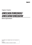
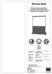
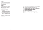
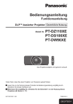
ALLGEMEINES - GENERAL
Zubehör - Accessories
KLEMMHALTER - CONNECTOR
ALLGEMEINES
Durch den modularen Aufbau können die Fußstützen nur in den
unteren Eckelementen verschraubt werden. Um die stabilisierende
Wirkung der Füße optimal zu nutzen, empfehlen wir die Verwendung
von Klemmhaltern (Connector). Das System VARIO 64 wird
standardmäßig mit Klemmhaltern geliefert. Der Klemmhalter Connector wird am oberen Ende des Fußes mit der Schraube zwischen
Fuß und Rahmenprofil aufgeschoben und fixiert. Der Kunststoffflügel
der Schraube ist dabei nach Außen gerichtet. (siehe Abb. links)
QUALITÄT
CONNECTOR
Due to the modular design of the System VARIO 32 and VARIO 64,
the leg supports can only be attached at the lower corner joints. To
make the most of the optimum stabilizing effect of our high legs, we
recommend using these connectors.
The connector has to be placed on the top end of the leg with the
screw situated in between of the frame and leg profile. The plastic wing
of the screw is thereby looking outwards. (see photos left)
DIAGONALVERSTREBUNG ANTI-SWAY BRACE
Zur Erhöhung der Seitenstabilität wir die in der Länge verstellbare
Diagonalverstrebung am Fuß angeschraubt und am Rahmenprofil
festgeklemmt.
ANTI-SWAY BRACE
To increase the side-stability of the projection screen the in length
variable ANTI-SWAY BRACE has to screwed on the leg and clamped to the
basic frame.
DRAPE KIT - der bühnengerechte Rahmen für Ihre Projektionswand
Wird die Projektionswand mit Dekorvorhängen verkleidet, so werden
je nach Bedarf die Rahmenteile VALANCE BAR und/oder WING BAR
aufgesteckt und die Dekorvorhänge angebracht.
Sehr schwere Dekorvorhänge werden nach dem Aufrichten der
Projektionswand angebracht, da das hohe Gewicht der Vorhänge zu
Beschädigungen des DRAPE KITS führen kann!
DRAPE KIT - turns your projection screen into a stage
To drape a projection screen with decoration curtains, you have to snap on the frame parts
VALANCE BAR and/or WING BAR as necessary. Heavy drapes have to be attached after the
erection to avoid damaging of frame parts!
DRAPE RUNOFF SYSTEM
DRAPE RUNOFF SYSTEM
Dieses universelle, transportable DRAPE SYSTEM kann als
freistehender Raumteiler, als Abgrenzung von Regieplätzen
oder beliebig zur flexiblen Raumgestaltung eingesetzt
werden.
Mit nur wenigen verschiedenen Elementen und dem
Teleskopprofil können innerhalb weniger Minuten ohne
Werkzeug unterschiedlichste Dekorationsaufgaben erfüllt
werden. Die Befestigung der Dekorstoffe erfolgt mittels
Velcro-Klettband.
This universal and transportable DRAPE SYSTEM can be used as independent partition, to
mark out control areas or to allow flexible room design. A few elements combined with
the telescopic system suffice to accomplish a variety of decorative purposes – no tools
required. The decoration material is attached by Velcro fasteners.
TRANSPORTKOFFER
UND
SICHERHEIT:
GARANTIE:
Die Garantie für Produktionsmängel beträgt für das Rahmensystem 5 Jahre und für die
Projektionsfolie 24 Monate.
Mobile Projektionswände wurden für den Einsatz im Innenbereich entwickelt. Schäden und
Folgeschäden, die durch den Einsatz im Außenbereich verursacht werden, sind daher von der
Garantie ausgenommen.
RAHMENSYSTEM: Die Rahmenteile, Füße und Anbauelemente sind wartungsfrei!
PROJEKTIONSFOLIE:
!
!
Die Projektionsfolie darf nicht beschriftet werden!
Farben dringen in die Projektionsfolie ein und können nicht mehr entfernt werden!
Die Projektionsfolie nur im gesäuberten und trockenen Zustand bei Raumtemperatur lagern!
Die Folie immer mit der Projektionsseite nach innen falten, damit eine Verschmutzung und
Beschädigung vermieden wird.
Wurde die Projektionsfolie bei niedrigen Temperaturen transportiert, so sollte die Folie erst nach
Erreichen der vollen Elastizität bei Raumtemperatur aufgespannt werden.
Beim Zusammenfalten der Projektionsfolie immer den mitgelieferten Schaumstoff zwischen
Druckknöpfe und Folie geben, damit keine bleibenden Abdrücke entstehen.
REINIGUNG
DER
PROJEKTIONSFOLIE:
Zum Reinigen verwenden Sie ein in Wasser (optional Seifenwasser) getränktes weißes
Baumwolltuch und wischen damit geradlinig (nicht kreisend) über die betroffene Stelle.
Mit einem weiteren Baumwolltuch trocken wischen.
Um hartnäckige Flecken zu entfernen, verwenden Sie Spiritus und ein weißes Baumwolltuch.
Verfahren Sie in gleicher Weise wie bei Wasser. Bei ungleichmäßiger Reinigung können sich
Schlieren bilden. Rückprojektionsfolien daher nur bei absoluter Notwendigkeit reinigen!
GENERAL
QUALITY
AND SAFETY:
This projection screen is in accordance with the safety regulations in DIN standard 19045. The
screen fabric is in accordance to DIN 4102 part 1.
WARRANTY:
The warranty period for production deficiencies is 5 years for the frame elements and
24 months for the projection surface.
Mobile projection screens are developed for indoor use only. Any damage and consequential
damage caused by outdoor use is not covered by warranty.
FRAME ELEMENTS: The frame elements, legs and additional elements are maintenance-free!
PROJECTION SURFACE:
The projection surface is packed into a separate soft bag to avoid any damage by the frame
parts, bleaching and discoloration.
Additionally following handling instructions have to be adhered to:
!
!
Do not bring printed and coloring objects (instructions, magazines, etc.) in contact with the
projection surface.
Do not mark the projection surface!
FLIGHT CASES
When folding the projection surface, insert the enclosed foamed plastic foil between snap
buttons and surface to avoid permanent marks.
As an option, we offer sturdy, stackable transport cases with rollers
for all mobile projection screens.
Transport case small: size 123 x 38 cm, height 34 cm
Transport case large: size 134 x 38 cm, height 37 cm
INSTRUCTIONS FOR MOBILE PROJECTION SCREENS
VARIO 32 AND VARIO 64
Bedruckte oder färbende Gegenstände (Anleitung, Zeitschriften etc.) dürfen nicht in Kontakt
mit der Projektionsfolie kommen.
Transportkoffer groß: Größe 134 cm x 38 cm, Höhe 37 cm
Transportkoffer klein: Größe 123 cm x 38 cm, Höhe 34 cm
ANLEITUNG FÜR MOBILE PROJEKTIONSWÄNDE
VARIO 32 UND VARIO 64
Die Projektionsfolie ist gesondert in einem Futteral verpackt und somit vor Beschädigung durch
das Rahmengestänge, dem Ausbleichen und Verfärbungen geschützt.
In der Handhabung sind zusätzlich folgende Kriterien zu berücksichtigen:
Colors penetrate the projection surface and cannot be cleaned anymore!
Store the projection surface, cleaned and dry at room temperature only!
The projection surface has to be folded with the front layer inside; in order to avoid soil and
damage.
When transporting the projection surface at low temperatures, do not attach the surface unless
it has reached its full elasticity at room temperature.
Als Option stehen für alle mobilen Projektionswände robuste,
stapelbare Koffer mit Rollen zur Verfügung.
MediumFold
Standard
Diese Projektionswand entspricht den sicherheitstechnischen Anforderungen nach DIN 19045.
Das Bildwandmaterial entspricht DIN 4102 Teil 1.
CLEANING
OF THE PROJECTION SURFACE:
Use a white clean cotton cloth saturated with clear water (optionally mild soap water) and gently
wipe the area in one direction (no circular motion). Wipe dry with another cotton cloth.
To clean a stubborn stain, use methylated spirit and follow the same procedure.
Clean rear projection surfaces in case of imperative only!
Änderungen, Irrtümer, Fehler vorbehalten !
Subject to modifications, errors expected !
w w w. AV s t u m p f l . c o m
Edition 1.08
AUFBAU
SET UP
VARIO - Die erweiterbare Projektionswand
VARIO - The extendible Screen System
System VARIO
5
1
2
6
7
8(9)
5
11
5
6
11
BASIC
Alle im Lieferumfang enthaltenen Teile der mobilen Projektionswand sind durch Etiketten
gekennzeichnet.
Beim Aufbau beginnen Sie mit dem Grundrahmen ( 1 2 3 4 ).
Die Eckteile 1 bis 4 aufklappen, die Scherengelenke aber noch nicht durchdrücken und die
Teile laut Beschriftung auf dem Boden auflegen.
Die Normteile 5 und Ausgleichsteile 6 gemäß Beschriftung und Skizze einfügen und den
Rahmen zusammenstecken. (siehe Skizze links)
Bei zwei Ausgleichsteilen 6 pro Rahmenseite werden die Normteile 5 (110cm) zwischen
die Ausgleichsteile 6 eingefügt. Das anschließende Durchdrücken der Scherengelenke
verleiht dem Rahmen die notwendige Stabilität.
All components of the mobile projection screen are labled.
MITTELSTÜTZEN
Die Mittelstütze besteht aus zwei Profilen “Mittelstütze” 7 und je nach Bildgröße aus den
Profilen “Normteil Mittelstütze” 8 und “Ausgleichsteil Mittelstütze” 9. Diese Teile werden
so zusammengesteckt, dass je ein Profil “ Mittelstütze” 7 mit der Steckzunge außen zu
liegen kommt. Schieben Sie die Mttelstütze nun zwischen Ober- und Unterkante des fertig
aufgebauten Bildwandrahmens, richten Sie sie mittig ein und befestigen diese mit zwei
Flügelschrauben. Die Schrauben sitzen an der Rückseite des Bildwandrahmens an den
Enden der Mittelstütze.
6
7
3
GRUNDRAHMEN
System VARIO 32 wird ab einer Bildwandbreite von 500cm mit Mittelstütze, ab einer Breite
von 600cm mit zusätzlichem Mittelfuß geliefert.
System VARIO 64 wird über einer Bildwandbreite von 700cm mit Mittelstütze und Mittelfuß
geliefert.
4
5
10
Nun die Bildwandfolie auf den Rahmen legen. Die Folie muss mit der Etikette
„Randverstärkung oben“ am Rahmenoberteil befestigt werden.
Befestigen Sie die Projektionsfolie indem Sie bei einer Ecke beginnen und die Druckknöpfe
der Reihe nach fixieren.
10
!
Bitte beachten Sie die Hinweise für Projektionsfolien unter ALLGEMEINES!
KLAPPBARE FÜSSE
!
T 32
AT 32
AT 32/64
AT 48
AT 64
min: 6cm
max: 82cm
min: 6cm
max: 113cm
min: 9cm
max: 146cm
min: 9cm
max: 161cm
min: 9cm
max: 176cm
220 cm
320 cm
430 cm
ZUR
HÖHENVERSTELLUNG
Die Füße 10 werden in der gewünschten Aufstellhöhe mit
jeweils zwei Flügelschrauben am Rahmen befestigt und die
Klemmhalter 11 am oberen Ende des Fußes angebracht
(siehe Zubehör - Klemmhalter-Connector)
KLAPPBARE FÜSSE - FOLDABLE LEGS:
415 cm
Bitte beachten Sie die maximale Aufstellhöhe der Füße!
(siehe Abb. „Klappbare Füße“ links)
min: minimale Höhe der Rahmenunterkante
max: maximale Höhe der Rahmenunterkante ohne zusätzliche Sicherung
550 cm
Aufstellhöhen sind Richtwerte und müssen der Größe der Projektionswand und den
Umgebungsbedingungen angepasst werden.
Aufstellhöhen sind gültig bei absolut senkrechter Aufstellung ohne zusätzliche
Krafteinwirkungen (Wind, Luftzug bei Klimaanlagen,..)
Für hohe Anforderungen an die Eigenstabilität, z.B. bei größeren Projektionswänden oder
großer Aufstellhöhe, empfehlen wir die Verwendung von Füßen der Baureihe:
AT 32 für VARIO 32 sowie AT 64 für VARIO 64.
AT-Füße haben eine ausziehbare Stütze, die mit zwei Flügelschrauben festgeklemmt wird.
AUFRICHTEN
YES
NO
(siehe Abbildungen links „YES / NO“)
Die Projektionswand mit jeweils einer Person an den oberen Bildwandecken anheben und
entlang der vertikalen Rahmenteile aufrichten.
Um eine Überbelastung oder Beschädigung von Rahmenelementen und Füßen zu
vermeiden, muss bei großen Projektionswänden oder bei großer Aufstellhöhe die Bildwand
mit einer angemessenen Personenanzahl aufgerichtet werden!
Zur Stabilisierung drücken Sie nach dem Aufrichten die Scherengelenke der Füße durch
und/oder verschrauben die Fußstütze mit dem Vertikalteil des Fußes.
!
Die Fußstütze immer erst nach dem Aufrichten mit dem Vertikalteil verschrauben!
ABBAU
Mit je einer Person pro klappbarem Fuß die Fußstützen und Scherengelenke an den
Füßen lösen. Danach die Projektionswand umlegen, indem man entlang der Füße und der
seitlichen Rahmenteile die Projektionswand in Richtung der oberen Ecken unterstützt.
!
For assembly, start with the basic frame ( 1 2 3 4 ).
Unfold the corner elements 1 to 4. Do not engage the shear joints now and lay out the
components according to their labelling.
The standard elements 5 (110cm) and supplementary frame components 6 have to be
inserted according to to their labelling (see sketch left).
In case of two supplementary frame components 6 per frame side, the standard
elements 5 (110cm) have to be placed in between of the two supplementary frame
components 6. Engaging the shear joints ensures the maximum screen stability.
CENTRE SUPPORT
The center support consists of two profiles „centre support“ 7 and additional,
according to the screen size, of parts “standard component - centre support“ 8 and a
“supplementary component-centre support“ 9. These components are assembled so that
one profile “centre support“ 7 each is placed with the attachement plate facing outside.
Slide the centre support between top and bottom edge of the assembled screen frame,
align it centrically and clamp the centre support with two wing screws from the backside
to the screen frame.
System VARIO 32 is supplied with one middle strut from a width of 500cm, additionally with
one middle leg from a width of 600cm.
System VARIO 64 is supplied with one middle strut and one middle leg over a width of
700cm.
PROJECTION SURFACE
PROJEKTIONSFOLIE
6
FRAME
Bitte beachten Sie die Hinweise für Projektionsfolien unter ALLGEMEINES!
Lay out the screen surface on the frame with the projection side facing upwards.
Make sure that the surface label “SCREEN TOP“ is positioned at the top bar of the frame.
Press on the projection surface by starting at one corner and fasten the buttons
one by one.
!
Please mind the instructions for projection surfaces in chapter GENERAL!
FOLDABLE LEGS
FOR HEIGHT ADJUSTMENT
The legs 10 have to be screwed to the basic frame
in the desired set-up height. Use the enclosed wing screws.
Now clamp the connectors 11 to the upper end of the legs
(see “Accessories“ - Connector).
!
Please mind the maximum set-up height of the legs!
(according sketches „Foldable Legs“ on the left)
min: minimum height of the bottom edge of the frame
max: maximum height of the bottom edge of the frame without additional safeguarding
Set-up heights are points of reference and have to be adapted in accordance with
the screen size and ambient conditions.
Set-up heights are based on absolute vertical erection without additional force effects
(e.g.: wind, air condition draught,..)
When a high degree of stability is needed, especially with large screens or a high set-up
height, we recommend using following legs:
AT 32 for VARIO 32 and AT 64 for VARIO 64
AT-Legs have a telescopic support that is tightend with two wing screws.
PUT UP
(see sketches „YES / NO“ on the left)
Lift the projection screen with one person each on the top corners and put it up by
supporting the screen along the vertical frame elements.
To avoid mechanical overload and damage of screen elements and legs with large screens
or high set-up height, the screen has to be erected with an appropriate number of
persons.
Engage the shear joints to ensure the stability and screw on the support to the vertical
part of the leg.
!
Screw on the support after erecting of the screen only!
TEARDOWN
Open the shear joints and leg supports with one person each on the foldable legs.
Bring down the screen by supporting the screen along the legs and vertical frame
elements towards the top corner edges.
!
Please mind the instructions for projection surfaces in chapter GENERAL!