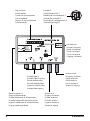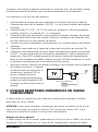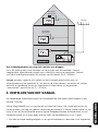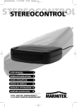
1
MEGAVIDEO55
AVIDEO
55
TM
USER MANUAL
3
GEBRAUCHSANLEITUNG 11
GUIDE UTILISATEUR
19
MODO DE EMPLEO
28
MANUALE D’ISTRUZIONI 36
GEBRUIKSAANWIJZING 44
20168 / 20061212 • MEGAVIDEO55™
ALL RIGHTS RESERVED MARMITEK © 2007
Dip switches
Schaltnocken
Cames de commutation
Conmutadores
Dentini di commutazione
Schakelnokjes
Jumper E
Verbindungsstück E
Bretelle de raccordement E
Puente de conexión E
Ponticello di collegamento E
Verbindingsbrugje E
E
S
Infrared out
Infrarot Ausgang
Sortie infrarouge
Salida infrarroja
Uscita infrarosso
Uitgang infrarood
Antenna out
Ausgang Antenne
Sortie antenne
Salida antena
Uscita antenna
Antenne uitgang
Audio/video in
Audio/Video Eingang
Entrée audio/video
Entrada audio/video
Ingresso Audio/Video
Audio/video ingang
Power adapter in
Eingang Netzadapter
Entrée adaptateur d'alimentation
Entrada adaptador de alimentación
Ingresso adattatore di alimentazione
Ingang voedingsadapter
2
Antenna in
Eingang Antenne
Entrée antenne
Entrada antena
Ingresso antenna
Antenne ingang
© MARMITEK
• To prevent short circuits, this product should only be used inside and only in dry spaces.
Do not expose the components to rain or moisture. Do not use the product close to a
bath, swimming pool etc.
• Do not expose the components of your systems to extremely high temperatures or bright
light sources.
• Do not open the product: the device contains live parts. The product should only be
repaired or serviced by a qualified repairman.
• In case of improper usage or if you have opened, altered and repaired the product
yourself, all guarantees expire. Marmitek does not accept responsibility in the case of
improper usage of the product or when the product is used for purposes other than
specified. Marmitek does not accept responsibility for additional damage other than
covered by the legal product responsibility.
• This product is not a toy. Keep out of reach of children.
• Adapters: Only connect the adapter to the mains after checking whether the mains voltage
is the same as the values on the identification tags. Never connect an adapter or power
cord when it is damaged. In that case, contact your supplier.
TABLE OF CONTENTS
INTRODUCTION ……………………………………………………………………............................................... 3
1. USE AND OPERATION OF THE MEGAVIDEO55…………………................................................ 3
2. SET CONTENTS…………………………………………………………………................................................. 4
3. CONNECTING APPLIANCES TO THE MEGAVIDEO55 MODULATOR................................ 4
4. CONNECTING THE AERIAL SIGNAL TO THE MEGAVIDEO55 MODULATOR...............
5
5. SETTING THE CHANNEL……………………………………………………................................................. 6
6. SETTING THE INFRARED RETURN CHANNEL FOR USING REMOTE CONTROL..........
7
7. USING INFRARED RECEIVERS IN DIFFERENT ROOMS……...................................................... 8
8. FREQUENTLY ASKED QUESTIONS…………………………………….................................................. 9
9. TECHNICAL DATA…………………………………………………………….................................................. 10
INTRODUCTION
Congratulations on purchasing the MegaVideo55! The MegaVideo55 is a programmable
stereo modulator that converts audio and video signals from, for instance, your DVD player,
satellite receiver, video recorder, security camera, decoder or PC and adds it to your aerial
cable as an extra channel. Then you can receive this signal as a kind of internal TV channel
anywhere in the house where you have an aerial connection.
1. USE AND OPERATION OF THE MEGAVIDEO55
You could say that the modulator is “looped into” the aerial signal. The incoming aerial signal
is connected to the aerial input. The audio/video signal (from a DVD player for instance) is
MEGAVIDEO 55TM
3
ENGLISH
SAFETY WARNINGS
added to the outgoing aerial signal. The added audio/video signal can now be viewed on the
channel that has been set on any televisions that are connected after the modulator (on the
‘RF ANT OUT' side of your MegaVideo55). You do not need to change any other part of your
aerial network.
Thanks to the built-in “infrared return channel” you can continue to operate the connected
appliances from other rooms using your own remote control. One infrared receiver is supplied
as standard. Additional receivers can be purchased should you wish to operate your
equipment from different rooms.
The infrared return channel only works with amplifiers, splitters and aerial wall outlets that
are return channel compatible. Compatible components are usually marked ‘5 – 30 MHz’ or
‘5 – 68 MHz’. Your aerial specialist can provide more information on this.
The modulator itself has no effect on the signal strength. The maximum length of cable that
can be used depends on the cable network in your house. If you want to connect a number
of TVs or use longer cable lengths it is recommended that you use an amplifying splitter. Your
aerial equipment supplier can give you advice on this.
2. SET CONTENTS
1x
1x
2x
1x
2x
2x
1x
1x
1x
Stereo modulator
Infrared receiver
Power adapter
RCA-RCA cable
Adapter F-connector to IEC-connector male
Adapter F-connector to IEC-connector female
Scart doubler
IR extender cable with 1 LED
User manual
3. CONNECTING APPLIANCES TO THE
MEGAVIDEO55 MODULATOR
Turn off all appliances before making any connections. Now attach the appliance you want to
connect (e.g. the DVD player) to the MegaVideo55. There are a number of ways to do this.
Using an RCA cable
All types of composite video signal and audio signal can be connected to the modulator. This
can be done using the supplied RCA cable. Ensure that the plug and socket colours match
each other. That is, red to red, white to white and yellow to yellow.
Using a scart cable
If the appliance you want to connect has a ‘scart connection’ you can use the supplied scart
doubler. When this is used you do not loose the use of the scart connection, so it can still be
4
© MARMITEK
ENGLISH
used for other applications. When the MegaVideo55 is connected to the scart doubler
(using the RCA cables on the side) and the scart cable that was originally connected to your
appliance at the same time, jumper E will have to be removed. The MegaVideo55 ensures
that picture quality is maintained.
Connecting a number of appliances
If you want to simultaneously connect several appliances to the modulator there are a
number of ways to do this:
Using a suitable A/V switcher
All of your appliances are connected to the A/V switcher. This option gives the best quality.
A good A/V switcher (such as the Marmitek Flat TV Link 4, art. no. 09592) takes care of
the correct modification of the signal.
Using a trio RCA splitter
(1x RCA to 2x RCA adaptors). In this case jumper E should be removed. The MegaVideo55
optimises picture quality.
4. CONNECTING THE AERIAL SIGNAL TO THE
MEGAVIDEO55 MODULATOR
INFRARED
RECEIVER
AERIAL
INFRARED
RECEIVER
IR LED
Two types of aerial plug are used in Europe: the IEC plug and the F plug. The latter has the
least loss and is therefore often used in better quality systems. Your Marmitek MegaVideo55
uses this type of plug. Check your situation below:
MEGAVIDEO 55TM
5
You are using F plugs
Connect the aerial cable coming from you aerial source to the input marked ‘RF ANT IN’.Then
connect the aerial cable leading to the rest of your aerial network to the output marked RF
ANT OUT'.
You are using IEC plugs
Adaptors are supplied in case you are using IEC plugs. Then follow the same procedure as
described above.
Your connecting cables have not yet been fitted with plugs
In this case ensure that the plugs are correctly fitted to the coax cable. Use high frequency
screened plugs to avoid external radiation and interference. Only use broadband amplifiers
and splitters with a range from 5 - 1000 MHz.
NOTE: If you want to use the infrared return channel for your remote control (see chapter 6)
then the aerial wall outlets, amplifiers and splitters that are included IN the cabling between
your bedroom and living room should be “return channel” compatible (5 – 30 MHz).
5. SETTING THE CHANNEL
The audio/video signal that has been added (e.g. from a DVD player) is converted into a normal TV
channel.
Using the MegaVideo55 you can, in principle, choose any free channel. It is important to select a
free channel that is not already being used for an existing TV channel. The channels that are free
depend on the incoming aerial signal. For details consult the channel table supplied by your cable
company or, if you have your own aerial, the channel summary in your TV magazine.
1. Connect one of the two power adapters to the modulator and plug it into the mains.
2. Check your channel table and find two free channels that are adjacent. Now select the higher of
these two channels. Example: if channels 37 and 38 are free then select channel 38. If three
adjacent channels are free select the middle channel.
3. Set your selected channel using the dip switches on the front of the modulator.
The white dip switches can be set in two positions: ON (= 1, switch up) and OFF (= 0, switch
down). The combination of switches determines the channel setting. It is easier to do this using a
small screwdriver or a ballpoint pen.
You can find the correct dip switch positions for the channel you have selected in the table at the
end of this manual. For instance, channel 38 would be 01100100. The 2nd, 3rd and 6th dip
switches are ON (up) and the remaining dip switches are OFF (down).
6
© MARMITEK
4. After you have set the channel you can turn on a test pattern using the 8th dip switch. To do
this set the dip switch to ON (= 1). This pattern consists of a number of black and white bars
on the screen.
5. Turn on the TV and find the channel that you have set. Your TV’s operating instructions will tell
you how to do this. You will now see the test pattern on the set channel. Now check that there
is no interference on the neighbouring TV channels. If there is, you should select another two
(or if possible) three free channels and set the modulator to these channels.
After you have done this set the 8th dip switch (test pattern) back to OFF. From now on you will be
able to watch the attached A/V appliance on the channel that you have set.
6. Now turn on the required A/V appliance (DVD, video recorder, satellite receiver, PC, camera,
etc.). You can now view the signal on the TV. If you have a number of TVs connected to the
same aerial network then you can also view this signal on the other TVs. To do so you will first
have to set the correct channel on each TV.
.
6. SETTING THE INFRARED RETURN CHANNEL FOR
USING REMOTE CONTROL
An infrared receiver is supplied with the set. This receiver can be fitted between the TV
and the aerial signal. The receiver converts the infrared signal from your remote control
and sends this signal back to the modulator through the aerial cable. Works with
almost all brands and models of remote controls (except B&O).
Using the supplied infrared eye you can convert this back to an infrared signal and send
it to the connected appliance. In this way you can operate the connected appliance
(e.g. a DVD player) from another room. It is easier to connect this if someone helps
you.
1. Disconnect the aerial cable connected to the back of your TV. Connect this to the
‘ANT IN’ / ‘In’ connection on the metal part of your infrared receiver.
2. Reconnect the ‘TV OUT’ / ‘To TV’ side to your TV. You can use the supplied
adaptors for this (F connector to IEC).
MEGAVIDEO 55TM
7
ENGLISH
NOTE:
• The leftmost 7 switches (1 to 7 incl.) are for setting the channel.
• The 8th switch is used to turn the test picture on or off (up is on). That is why this switch is
normally shown in the 0 position in the attached list.
• Use the 9th switch to choose between a high (ON setting = 82dBµV) and a low (OFF setting =
72dBµV) output power. If you see interference (white noise) on the screen of the MegaVideo55,
please set this switch to a different setting. NB: if the output power is too high, this can also
cause interference!
3. Position the red plastic part containing the infrared receiver where it can be seen
from where you want to use your remote control. Avoid direct sunlight or light
from a plasma screen.
4. Connect one of the two supplied transformers to the metal part of the IR receiver.
5. Turn the switch on the side of the red plastic part to the ON position.
6. Connect the supplied IR extender cable to the side of the modulator, where it is
marked ‘IR OUT’. The IR LED has a self-adhesive backing. Remove the protective
sheet and stick the IR LED carefully over the IR sensor on your video recorder, DVD
player or satellite receiver. This IR sensor can usually be recognised by the dark
coloured plastic window.
7. Point your own remote control at the infrared receiver and press a button, for
instance one used to change the channel or select a different function. If all is well
the attached appliance will now react. If not, then move the IR LED and try again.
The location in which the IR LED responds can sometimes be very small. As soon as
the function works correctly you can firmly attach the eye to the appliance. This will
not damage your appliance.
INFRAREDRECEIVER
RECEIVER
INFRARED
7. USING INFRARED RECEIVERS IN DIFFERENT ROOMS
If you want to operate your appliance from a number of TVs you can purchase extra infrared
receivers (art. no. 09586).
NOTE: If you have more than one receiver ensure that only one of these receivers is switched
on at any time (one receiver switched ‘ON’ and the other receivers switched ‘OFF’). If you fail
to do this your infrared commands will not be transmitted correctly.
8
© MARMITEK
8. FREQUENTLY ASKED QUESTIONS
No picture, no sound.
a. Check that all cables are correctly connected.
b. Check that the channel has been set correctly.
c. Check that the test pattern is received correctly.
The image on the MegaVideo55 is suffering from interference, while all the other TV
stations are shown normally.
a. Use the 9th switch to choose between a high (ON setting = 82dBµV) and a low (OFF
setting = 72dBµV) output power. If you see interference (white noise) on the screen of the
MegaVideo55, please set this switch to a different setting. NB: if the output power is too
high, this can also cause interference!
b. One of the TV channels is too close to the channel used by the MegaVideo55. Choose a
different channel for the MegaVideo55 (preferably the middle of three or if possible the
middle of five free channels).
I cannot find the image of the MegaVideo55 on my set.
Switch off the MegaVideo55 test picture and connect e.g. a DVD player. Now search for the
image of your DVD instead of the test picture.
The picture is far too bright.
Check that the jumper switch has been correctly connected.
The picture is far too dark.
Check that the jumper switch has been correctly disconnected.
Interference with other channels.
Select a different channel, preferably the middle channel of 3 empty channels in the band.
Sound is distorted.
Turn down the volume on the connected appliance.
Infrared does not work.
a. Check that the IR LED is in the correct position on the sensor.
b. Check that the metal part of the infrared receiver is correctly connected.
c. Check that the aerial wall outlets, aerial amplifiers and splitters that are fitted IN the cabling
between your bedroom and living room are "return channel" compatible (5 - 30 MHz).
MEGAVIDEO 55TM
9
ENGLISH
Operating more than one appliance
If you want to operate more than one appliance by means of infrared you can purchase the IR
Eye (art. no. 09682). This model has 2 IR LED’s for, for instance, DVD and satellite receiver.
Do you still have questions? Please check out www.marmitek.com for more
information.
9. TECHNICAL DATA
Stereo RF Modulator:
Power:
Standard:
Modulation frequency range:
Input:
Selectable output level:
Coupling loss:
Carrier wave Audio:
Modulation method:
Dimensions:
230VAC/50Hz, DC 9V/300mA
PAL B/G
UHF:470~862MHz Channel 21-69
Video, Audio L+R
82 dBµV / 72 dBµV in 75 Ohm
<1.5dB at 860Mhz
5.5 – 5.742MHz
Double sideband modulation
85.8x68.4x21.3mm
IR Receiver:
Power:
Centre frequency:
Infrared:
Coupling loss:
Dimensions:
230VAC/50Hz, DC 9V/300mA
27.045MHz
≤40KHz
<3 dB at 860Mhz
44x47x18mm
Environmental Information for Customers in the European Union
European Directive 2002/96/EC requires that the equipment bearing this symbol on the product and/or its
packaging must not be disposed of with unsorted municipal waste. The symbol indicates that this product
should be disposed of separately from regular household waste streams. It is your responsibility to dispose
of this and other electric and electronic equipment via designated collection facilities appointed by the
government or local authorities. Correct disposal and recycling will help prevent potential negative
consequences to the environment and human health. For more detailed information about the disposal of your old
equipment, please contact your local authorities, waste disposal service, or the shop where you purchased the
product.
10
© MARMITEK
• Um Kurzschluss vorzubeugen, dieses Produkt bitte ausschließlich innerhalb des Hauses und
nur in trockenen Räumen nutzen. Setzen Sie die Komponenten nicht Regen oder
Feuchtigkeit aus. Nicht neben oder nahe eines Bades,Schwimmbades usw. verwenden.
• Setzen Sie die Komponente Ihres Systems nicht extrem hohen Temperaturen oder starken
Lichtquellen aus.
• Das Produkt niemals öffnen: Das Gerät enthält Bestandteile mit lebensgefährlicher
Stromspannung. Überlassen Sie Reparaturen oder Wartung nur Fachleuten.
• Bei einer zweckwidrigen Verwendung, selbst angebrachten Veränderungen oder selbst
ausgeführten Reparaturen verfallen alle Garantiebestimmungen. Marmitek übernimmt bei
einer falschen Verwendung des Produkts oder bei einer anderen Verwendung des
Produktes als für den vorgesehenen Zweck keinerlei Produkthaftung. Marmitek übernimmt
für Folgeschäden keine andere Haftung als die gesetzliche Produkthaftung.
• Dieses Produkt ist kein Spielzeug. Außer Reichweite von Kindern halten.
• Netzadapter: Schließen Sie den Netzadapter erst dann an das Stromnetz an, nachdem Sie
überprüft haben, ob die Netzspannung mit dem auf dem Typenschild angegeben Wert
übereinstimmt. Schließen Sie niemals einen Netzadapter oder ein Netzkabel niemals an,
wenn diese beschädigt sind. In diesem Fall nehmen Sie Kontakt mit Ihrem Lieferanten auf.
INHALTSANGABE
EINFÜHRUNG ……………………………………………………………………....................................................
1. ANWENDUNG UND BETRIEBSWEISE DES MEGAVIDEO55……….......................................
2. VERPACKUNGSINHALT……………………………………………………..................................................
3. DAS ANSCHLIEßEN VON GERÄTEN AN DEM MEGAVIDEO55 MODULATOR.............
4. DAS ANSCHLIEßEN DES ANTENNENSIGNALS AN DEN MEGAVIDEO55 MODULATOR..
5. DAS EINSTELLEN DES KANALS……......……………………………….................................................
6. DAS INSTALLIEREN DES INFRAROT-HILFSKANALS FÜR DIE BENUTZUNG DER
FERNBEDIENUNG..........……………………………………………………...................................................
7. DIE BENUTZUNG VON INFRAROT-EMPFÄNGERN IN MEHREREN RÄUMEN…...........
8. HÄUFIG GESTELLTE FRAGEN……………..........………………………..................................................
9. TECHNISCHEN DATEN………………………..……………………………..................................................
11
12
12
12
13
14
16
17
17
18
EINFÜHRUNG
Herzlichen Glückwunsch zum Erwerb des MegaVideo55! Der MegaVideo55 ist ein
programmierbarer Stereo-Modulator, der Audio- und Videosignale, z. B. Ihres DVD-Spielers,
Satellitenempfängers, Videorecorders, Ihrer Überwachungskamera, Ihres Decoders oder PCs
umsetzt, und als zusätzlichen Sender an Ihr Antennenkabel zufügt. Anschließend können Sie
sich dieses Signal überall dort im Haus, wo Sie über einen Antennenanschluss verfügen, als
eine Art internen Fernsehkanal betrachten.
MEGAVIDEO 55TM
11
DEUTSCH
SICHERHEITSHINWEISE
1. ANWENDUNG UND BETRIEBSWEISE DES
MEGAVIDEO55
Der Modulator wird sozusagen in das Antennensignal ‘eingefädelt’. Das eingehende
Antennensignal wird an den Antenneneingang angeschlossen. Das ausgehende
Antennensignal ist mit einem zugefügten Audio- und Videosignal (beispielsweise eines DVDSpielers) ausgestattet. Auf allen Fernsehgeräten, die an die dem Modulator nachgeschaltete
Antennenanlage angeschlossen sind (an der Seite von ‘RF ANT OUT’ Ihres MegaVideo55),
kann das zugefügte Audio- und Videosignal auf dem eingestellten Kanal betrachtet werden.
Am verbleibenden Antennennetzwerk brauchen Sie keine Änderungen vorzunehmen.
Dank des sog. eingebauten “Infrarot-Hilfskanals” können Sie die angeschlossenen Geräte
auch weiterhin von anderen Räumen aus mit Ihrer eigenen Fernbedienung bedienen.
Serienmäßig wird ein Infrarot-Empfänger mitgeliefert. Wenn Sie Ihre Geräte von mehreren
Räumen aus bedienen wollen, können Sie sich zusätzliche Empfänger anschaffen.
Der Infrarot-Hilfskanal funktioniert nur mit Verstärkern, Verteilern und Antennenbuchsen, die
für einen Hilfskanal geeignet sind. Das wird meistens auf den betreffenden Komponenten mit
der Kennzeichnung ‘5-30MHz of 5-68MHz’ angegeben. Weitere Informationen darüber
erhalten Sie bei Ihrem Antennen-Fachhandel.
Der Modulator selbst hat keinen Einfluss auf die Signalstärke. Die zu verwendenden
Kabelhöchstlängen sind von dem in Ihrem Haus vorhandenen Kabelnetzwerk abhängig. Wenn
Sie mehrere Fernsehgeräte anschließen oder größere Kabellängen verwenden wollen,
empfehlen wir Ihnen einen Verteilerverstärker. Ihr Fachhändler für Antennenmaterial kann Sie
diesbezüglich beraten.
2. VERPACKUNGSINHALT
1x
1x
2x
1x
2x
2x
1x
1x
1x
Stereo-Modulator
Infrarot-Empfänger
Speiseadapter
Cinch Kabel
Adapter F-Steckverbinder zum IEC Steckverbinder Male
Adapter F-Steckverbinder zum IEC Steckverbinder Female
Scart-Doubler (Verdoppler)
IR-Verlängerungskabel mit 1 LED
Gebrauchsanleitung
3. DAS ANSCHLIEßEN VON GERÄTEN AN DEM
MEGAVIDEO55 MODULATOR
Schalten Sie vor dem Anschließen alle Geräte aus. Schließen Sie nun das von Ihnen
gewünschte Gerät (beispielsweise einen DVD-Spieler) an den MegaVideo55 an. Dafür stehen
12
© MARMITEK
Ihnen verschiedene Möglichkeiten zur Verfügung.
Mit Hilfe eines Scart-Kabels
Wenn das anzuschließende Gerät einen sogenannten ‘Scart-Anschluss’ besitzt, können Sie
auch den mitgelieferten Scart-Verdoppler benutzen. Bei Benutzung des Scart-Verdopplers
steht der Scart-Anschluss auch weiterhin zur Verfügung, sodass Sie ihn auch für andere
Verwendungszwecke benutzen können. Wenn Sie sowohl den MegaVideo55 (über die CinchKabel an der Seite) als auch das ursprünglich an Ihr Gerät angeschlossene Scart-Kabel an den
Scart-Verdoppler anschließen wollen, müssen Sie Verbindungsstück E entfernen. Der
MegaVideo55 sorgt nun dafür, dass die Bildqualität erhalten bleibt.
Mehrere Geräte anschließen?
Für den Fall, dass Sie mehrere Geräte gleichzeitig an den Modulator anschließen wollen,
haben Sie verschiedene Möglichkeiten:
Mit Hilfe eines geeigneten A/V-Schalters
An diesen Schalter werden alle Ihre Geräte angeschlossen. Mit dieser Möglichkeit erzielen Sie
die beste Qualität. Ein guter A/V-Schalter (wie der Marmitek Flat TV Link 4, Art.-Nr. 09592)
sorgt für eine richtige Abstimmung der Signale.
Mit Hilfe von drei Cinch-Verteilern
(Reduzierstück von 1x Cinch zu 2x Cinch). In diesem Fall müssen Sie Verbindungsstück E
entfernen. Der MegaVideo55 optimiert nun die Bildqualität.
4. DAS ANSCHLIEßEN DES ANTENNENSIGNALS AN
DEN MEGAVIDEO55 MODULATOR
Wir kennen in Europa zwei Arten von Antennenstecker: den IEC-Stecker und den F-Stecker.
Letztgenannter hat den geringsten Verlust und wird daher häufig in qualitativ besseren
Anlagen verwendet. Auch Ihr Marmitek MegaVideo55 ist mit einem solchen Stecker
ausgerüstet. Sehen Sie nachstehend nach, welche Situation für Sie zutrifft.
Sie verwenden F-Stecker
Das Antennenkabel, das von Ihrer Antennenquelle kommt, schrauben Sie an den Eingang mit
der Kennzeichnung ‘RF ANT IN’. Das Antennenkabel, das zum verbleibenden
Antennennetzwerk führt, schließen Sie an den Ausgang mit der Kennzeichnung ‘RF ANT
OUT’ an.
MEGAVIDEO 55TM
13
DEUTSCH
Mit Hilfe eines Cinch-Kabels
An den Modulator kann jedes sog. Composite-Videosignal und Audiosignal angeschlossen
werden. Sie können dafür das mitgelieferte Cinch-Kabel benutzen. Achten Sie darauf, dass
die Farben der Stecker und der Eingangsbuchsen miteinander übereinstimmen, d.h. rot an rot,
weiß an weiß und gelb an gelb.
INFRAROTEMPFÄNGER
ANTENNE
INFRAROTEMPFÄNGER
IR LED
Sie verwenden IEC-Stecker
Für den Fall, dass Sie IEC-Stecker verwenden, wurden Zwischenstecker mitgeliefert.
Im Weiteren gehen Sie, wie oben beschrieben, vor.
Ihre Verbindungskabel sind noch nicht mit Steckern ausgestattet
Achten Sie in diesem Fall auf eine richtige Montage der Stecker an das Koax-Kabel.
Verwenden Sie hochfrequenzabgeschirmte Stecker, um Einstrahlung und Störungen zu
verhindern. Benutzen Sie ausschließlich Breitbandverstärker und Verteiler mit einem Bereich
von 5-1000Mhz.
Warnhinweis: Wenn Sie den Infrarot-Hilfskanal für Ihre Fernbedienung (siehe Kapitel 6)
benutzen wollen, müssen die Antennenbuchsen, Verstärker und Verteiler, die IN die
Verkabelung zwischen Ihrem Schlafzimmer und Wohnzimmer aufgenommen sind, für einen
“Hilfskanal” (5 – 30 MHz) geeignet sein.
5. DAS EINSTELLEN DES KANALS
Das zugefügte Audio- und Videosignal (beispielsweise des DVD-Spielers) wird in einen normalen
Fernsehkanal umgesetzt.
Mit dem MegaVideo55 können Sie im Prinzip jeden freien Kanal selbst wählen. Es ist wichtig,
einen freien Kanal zu wählen, der noch nicht für einen bestehenden Fernsehkanal benutzt wird.
Welche Kanäle frei sind, hängt von dem eingehenden Antennensignal ab. Ziehen Sie diesbezüglich
die Kanalkarte Ihrer Kabelgesellschaft oder - falls Sie eine eigene Antenne haben – die
14
© MARMITEK
Die weißen Schaltnocken können Sie in zwei Stände schalten: ON (=1, Schalter nach oben) und
OFF (=0, Schalter nach unten). Die Kombination der Schalter bestimmt den eingestellten Kanal. Sie
können dafür am besten einem kleinen Schraubenzieher oder einen Kugelschreiber benutzen.
Sie finden den richtigen Stand der Schaltnocken für den von Ihnen gewählten Kanal hinten in
dieser Bedienungsanleitung. So stimmt beispielsweise Kanal 38 mit 01100100 überein. Die 2., 3.
und 6. Schaltnocken stehen dabei auf ON (nach oben), die übrigen auf OFF (nach unten).
Warnhinweis:
• Die 7 äußerst links gelegenen Schalter (1 bis 7) dienen für das Einstellen des Kanals.
• Mit dem 8. Schalter schalten Sie das Testbild ein oder aus (nach oben bedeutet eingestellt). Aus
diesem Grund steht dieser Schalter in der beigefügten Liste normal im Stand 0.
• Mit dem 9. Schalter wählen Sie zwischen einer hohen (ON Position = 82dBµV) und niedrigen
(OFF Position = 72dBµV) Ausgangssignal. Tritt eine Störung (rauschen) im Bild des MegaVideo55
auf, dann müssen Sie diesen Schalter verstellen. NB: Ein zu hohes Ausgangssignal kann auch zu
Störungen führen!
4. Nachdem Sie den Kanal eingestellt haben, können Sie mit dem 8.Schalter ein Testmuster
einstellen. Schalten Sie dafür die Nocke auf ON (=1). Dieses Muster besteht aus einigen
schwarz-weißen Balken auf dem Bild.
5. Schalten Sie das Fernsehgerät ein, und suchen Sie den von Ihnen eingestellten Kanal. Wie Sie
vorzugehen haben, finden Sie in der Bedienungsanleitung Ihres Fernsehgeräts. Auf dem
eingestellten Kanal sehen Sie jetzt das Testmuster. Prüfen Sie anschließend, ob keine Störung in
den nahegelegenen Fernsehgerät-Kanälen auftritt. Sollte das der Fall sein, müssen Sie zwei
(oder möglicherweise drei) andere freie Kanäle suchen und den Modulator darauf einstellen.
Jetzt schalten Sie den 8. Schalter (Testmuster) wieder auf OFF. Sie können sich das angeschlossene
A/V-Gerät nun fortan auf dem von Ihnen eingestellten Kanal ansehen.
6. Schalten Sie jetzt das gewünschte A/V-Gerät (DVD, Videorecorder, Satellitenempfänger, PC,
Kamera, usw.) ein. Sie können sich jetzt auf dem Fernsehgerät das Signal ansehen. Wenn Sie
mehrere Fernsehgeräte im Haus (am selben Antennennnetzwerk) besitzen, können Sie sich
dieses Signal auch auf den übrigen Fernsehgeräten ansehen. Sie müssen dafür erst an jedem
Fernsehgerät den richtigen Kanal einstellen.
MEGAVIDEO 55TM
15
DEUTSCH
Kanalübersicht in Ihrer Fernsehzeitung zu Rate.
1. Schließen Sie nun einen der zwei Netzadapter an den Modulator an, und stecken Sie ihn in die
Steckdose.
2. Nehmen Sie Ihre Kanalkarte zur Hand, und suchen Sie zwei nebeneinander gelegene, freie
Kanäle. Anschließend wählen Sie von diesen zwei Kanälen den am höchsten gelegenen Kanal.
Bespiel: Wenn Kanal 37 und 38 frei sind, wählen Sie Kanal 38. Bei drei freien Kanälen
nebeneinander, wählen Sie den mittleren Kanal.
3. Stellen Sie den von Ihnen gewählten Kanal mit Hilfe der Schalter an der Vorderseite des
Modulators ein.
6. DAS INSTALLIEREN DES INFRAROT-HILFSKANALS
FÜR DIE BENUTZUNG DER FERNBEDIENUNG
Mit dem Satz wird ein sogenannter Infrarot-Empfänger geliefert. Dieser Empfänger
kann zwischen das Fernsehgerät und das Antennensignal installiert werden. Der
Empfänger setzt das Infrarotsignal Ihrer Fernbedienung um und sendet das Signal über
das Antennenkabel zurück zum Modulator. Kann mit nahezu allen
Fernbedienungsmarken und -Modellen betrieben werden (Ausgen. B&O).
Mit dem mitgelieferten Infrarot-Auge können Sie wieder auf das Infrarot-Signal schalten
und es an das angeschlossene Gerät weiterleiten. So können Sie das angeschlossene
Gerät (beispielsweise einen DVD-Spieler) von einem anderen Raum aus bedienen.
Das Anschließen lässt sich am einfachsten mit 2 Personen vornehmen.
1. Lösen Sie das auf der Rückseite Ihres Fernsehgeräts angeschlossene Antennenkabel,
und schließen Sie es an den ‘ANT IN’ / ‘In’-Anschluss des Metallteils Ihres InfrarotEmpfängers an.
2. Schließen Sie die ‘TV OUT’ / ‘To TV’-Seite wieder an Ihr Fernsehgerät an. Sie können
dafür die mitgelieferte Zwischenbuchse benutzen (F Stecker zum IEC).
3. Montieren Sie das rote Plastikteil, das den Infrarot-Empfänger enthält, so, dass es zu
sehen ist, wenn Sie Ihre Fernbedienung benutzen. Vermeiden Sie direkte
Sonneneinstrahlung oder Licht eines Plasmaschirms.
4. Schließen Sie einen der zwei mitgelieferten Netzadapter an das Metallteil des IREmpfängers an.
5. Schalten Sie den Schalter an der Seite des roten Plastikteils in den ON-Stand.
6. Schließen Sie das mitgelieferte IR-Verlängerungskabel an die Seite des Modulators
mit der Kennzeichnung ‘IR OUT’ an. Das IR LED hat eine selbstklebende Rückseite.
Entfernen Sie das Schutzblatt, und kleben Sie das IR LED vorsichtig auf den
Infrarotsensor Ihres Videorecorders, DVD-Spielers oder Satellitenempfängers. Den
Infrarotsensor können Sie an dem dunkel gefärbten Kunststofffenster erkennen.
7. Richten Sie Ihre eigene
Fernbedienung jetzt auf den
Infrarot-Empfänger, und drücken
Sie auf die Taste, mit der Sie
beispielsweise einen anderen Kanal
oder eine andere
Funktion wählen. Wenn alles richtig
installiert wurde, reagiert das
16
INFRARED RECEIVER
INFRAROT-EMPFÄNGER
© MARMITEK
angeschlossene Gerät jetzt. Falls nicht, verschieben Sie dann das IR LED, und
versuchen Sie es noch einmal. Die Position des IR LED muss sehr präzise bestimmt
werden. Nachdem die Funktion richtig funktioniert, können Sie Infrarot-Auge fest
auf das Gerät kleben. Ihr Gerät wird dadurch nicht beschädigt.
DEUTSCH
7. DIE BENUTZUNG VON INFRAROT-EMPFÄNGERN IN
MEHREREN RÄUMEN
Wenn Sie Ihre Geräte an mehreren Fernsehgeräten bedienen wollen, können Sie sich
zusätzliche Infrarot-Empfänger anschaffen (Art.-Nr. 09586).
Wenn Sie mehr als einen Empfänger haben, achten Sie bitte darauf, dass immer nur einer
dieser Empfänger gleichzeitig eingeschaltet ist (ein Empfänger auf 'ON' und der andere
Empfänger auf 'OFF'). Tun Sie das nicht, werden Ihre Infrarot-Befehle nicht richtig
weitergeleitet.
Mehrere Gerät ansteuern
Wenn Sie mehrere Gerät mit Hilfe von Infrarot ansteuern wollen, können Sie den IR Eye (Art.Nr. 09682) kaufen. Diese Ausführung besitzt 2 IR LED’s, beispielsweise für DVD, Videorecorder
und Satellitenempfänger.
8. HÄUFIG GESTELLTE FRAGEN
Kein Bild, kein Ton.
a. Überprüfen Sie, ob alle Kabel richtig angeschlossen sind.
b. Überprüfen Sie, ob der Kanal richtig eingestellt ist.
c. Überprüfen Sie, ob das Testmuster richtig wiedergegeben wird.
MegaVideo55 Bild gibt Störung, alle anderen Fernsehsender sind in Ordnung.
a. Mit dem 9. Schalter wählen Sie zwischen einer hohen (ON Position = 82dBµV) und
niedrigen (OFF Position = 72dBµV) Ausgangssignal. Tritt eine Störung (rauschen) im Bild des
MegaVideo55 auf, dann müssen Sie diesen Schalter verstellen. NB: Ein zu hohes
Ausgangssignal kann auch zu Störungen führen!
b. Ein Fernsehkanal befindet sich zu nahe am für den MegaVideo55 eingestellten Kanal.
Nehmen Sie einen anderen Kanal für den MegaVideo55, wenn möglich den mittelsten von 3
oder besser noch 5 freien Kanälen.
Ich kann das Bild des MegaVideo55 auf meinem Gerät nicht finden.
Schalten Sie das Testbild des MegaVideo55 aus und schließen Sie z.B. einen DVD-Spieler an.
Suchen Sie nun das Bild Ihres DVD-Spielers anstatt Ihres Testbildes.
Das Bild ist viel zu hell.
Überprüfen Sie, ob das Verbindungsstück richtig montiert ist.
MEGAVIDEO 55TM
17
Das Bild ist viel zu dunkel.
Überprüfen Sie, ob das Verbindungsstück richtig entfernt wurde.
Interferenz mit anderen Kanälen.
Wählen Sie einen anderen Kanal, vorzugsweise den mittleren von 3 freien Kanälen im Band.
Verzerrter Ton.
Drehen Sie die Lautstärke des angeschlossenen Geräts zurück.
Infrarot funktioniert nicht.
a. Überprüfen Sie, ob sich die IR LED an der richtigen Stelle des Sensors befindet.
b. Überprüfen Sie, ob das Metallteil des Infrarot-Empfängers richtig angeschlossen ist.
c. Überprüfen Sie, ob die Antennenbuchsen, Antennenverstärker und Verteiler, die IN der
Verkabelung zwischen Ihrem Schlafzimmer und Wohnzimmer aufgenommen sind, für
“Hilfskanal” geeignet sind (5-30MHz).
Haben Sie noch immer Fragen? Besuchen Sie www.marmitek.com.
9. TECHNISCHEN DATEN
Stereo-Modulator:
Speisung:
System:
Modulation frequenzbereich:
Eingang:
Ausgangsniveau:
Anschlussverlust:
Trägerwelle Audio:
Modulationsmethode:
Abmessungen:
230VAC/50Hz, DC 9V/300mA
PAL B/G
UHF: 470 – 862MHz, Kanal 21-69
Video, Audio L+R
82 dBµV / 72 dBµV in 75Ohm
< 1,5dB bei 860MHz
5,5 en 5,742MHz
Doppelte Seitenband-Modulation
85,8x68,4x21,3mm
Infrarot-Empfänger.
Speisung:
Frequenz Zentrum:
Infrarot-Empfang:
Anschlussverlust:
Abmessungen:
230VAC/50Hz, DC 9V/300mA
27.045MHz
≤ 40kHz
< 3dB bei 860MHz
44x47x18mm
Umweltinformation für Kunden innerhalb der Europäischen Union
Die Europäische Richtlinie 2002/96/EC verlangt, dass technische Ausrüstung, die direkt am Gerät und/oder
an der Verpackung mit diesem Symbol versehen ist nicht zusammen mit unsortiertem Gemeindeabfall
entsorgt werden darf. Das Symbol weist darauf hin, dass das Produkt von regulärem Haushaltmüll getrennt
entsorgt werden sollte. Es liegt in Ihrer Verantwortung, dieses Gerät und andere elektrische und
elektronische Geräte über die dafür zuständigen und von der Regierung oder örtlichen Behörden dazu
bestimmten Sammelstellen zu entsorgen. Ordnungsgemäßes Entsorgen und Recyceln trägt dazu bei, potentielle
negative Folgen für Umwelt und die menschliche Gesundheit zu vermeiden. Wenn Sie weitere Informationen zur
Entsorgung Ihrer Altgeräte benötigen, wenden Sie sich bitte an die örtlichen Behörden oder städtischen
Entsorgungsdienste oder an den Händler, bei dem Sie das Produkt erworben haben.
18
© MARMITEK
• Afin d'éviter un court-circuit, ce produit ne doit être utilisé qu'à l'intérieur, et uniquement
dans des endroits secs. Ne pas exposer les composants à la pluie ou à l'humidité. Ne pas
utiliser à côté de ou près d'une baignoire, une piscine, etc.
• Ne pas exposer les composants de votre système à des températures extrêmement élevées
ou à des sources de lumières trop fortes.
• Ne jamais ouvrir le produit: l'appareil contient des éléments qui sont sous tension très
dangereuse. Les réparations ou l'entretien ne doivent être effectués que par des personnes
compétentes.
• Toute utilisation impropre, toute modification ou réparation effectuée vous-même annule
la garantie. Marmitek n’accepte aucune responsabilité dans le cas d’une utilisation
impropre du produit ou d’une utilisation autre que celle pour laquelle le produit est
destiné. Marmitek n’accepte aucune responsabilité pour dommage conséquent, autre que
la responsabilité civile du fait des produits.
• Ce produit n’est pas un jouet et doit être rangé hors de la portée des enfants.
• Adaptateur: Brancher l’adaptateur secteur sur le réseau électrique seulement après avoir
vérifié que la tension d’alimentation correspond à la valeur indiquée sur les plaques
d’identification. Ne jamais brancher un adaptateur secteur ou un cordon d’alimentation
lorsque celui-ci est endommagé. Dans ce cas, veuillez contacter votre fournisseur.
TABLE DES MATIÈRES
Introduction ……………………………………………………………………......................................................
1. Application et fonctionnement du MegaVideo55………......................................................
2. Contenu de l’emballage……………….………………………………….................................................
3. Connexion des appareils au modulateur MegaVideo55.....................................................
4. Connexion du signal d’antenne au modulateur MegaVideo55......................................
5. Sélection de la chaîne……......…..................…………………………….................................................
6. Installation du canal retour infrarouge pour permettre une utilisation de la
télécommande..........……………………………………..……………..........................................................
7. Utiliser des récepteurs infrarouges dans plusieurs pièces…..............................................
8. Foire aux questions………..................……..........………………………..................................................
9. Caractéristiques techniques……………....……………………………..................................................
19
20
20
21
21
22
24
25
25
27
INTRODUCTION
Merci d'avoir acheté le MegaVideo55 ! Le MegaVideo55 est un modulateur stéréo
programmable qui convertit les signaux vidéo provenant, par exemple, de votre lecteur DVD,
récepteur satellite, magnétoscope, caméra de surveillance, décodeur ou P.C., et les ajoute en
tant qu'émetteur supplémentaire à votre câble d'antenne. Vous avez ainsi la possibilité,
partout où vous disposez d'une borne d'antenne dans votre maison, de faire apparaître ce
signal comme une sorte de chaîne de télévision interne.
MEGAVIDEO 55TM
19
FRANÇAIS
AVERTISSEMENTS DE SECURITE
1. APPLICATION ET FONCTIONNEMENT DU
MEGAVIDEO55
Le modulateur est pour ainsi dire « intégré » dans le signal d'antenne. Le signal d'antenne
entrant est connecté sur la borne d'entrée d'antenne. Quant au signal d'antenne sortant, il
est doté d'un signal audio/vidéo additionnel (par exemple, celui d'un lecteur DVD). Sur tous
les téléviseurs raccordés à l'installation d'antenne après le modulateur (du côté « RF ANT OUT
» de votre MegaVideo55), le signal audio-vidéo additionnel peut être vu sur la chaîne
programmée. Aucun changement ne doit être apporté au niveau de votre réseau d'antenne.
Grâce au « canal retour infrarouge » intégré, vous avez également la possibilité de faire
fonctionner les appareils connectés à partir d'autres pièces, à l'aide de votre propre
télécommande. Un seul récepteur infrarouge est fourni de manière standard avec
l'installation. Si vous souhaitez faire fonctionner votre système à partir de plusieurs pièces,
vous aurez besoin de récepteurs supplémentaires.
Le canal retour infrarouge fonctionne uniquement lorsqu'il est fait usage d'amplificateurs, de
répartiteurs et de boîtiers d'antenne convenant pour ce type de canal retour. C'est
généralement indiqué sur la composante en question par la mention « 5-30MHz ou 5-68MHz
». Pour de plus amples informations à ce sujet, veuillez vous adresser auprès de votre magasin
d'antennes spécialisé.
Le modulateur en lui-même n'a aucune influence sur l'intensité du signal. Les longueurs
maximales de câble à respecter sont déterminées en fonction du réseau câblé présent dans
votre maison. Lorsque vous souhaitez raccorder plusieurs téléviseurs ou lorsque vous utilisez
des longueurs de câble plus importantes, nous vous recommandons d'avoir recours à un
amplificateur de distribution. Votre fournisseur de matériel d'antenne peut vous conseiller en
la matière.
2. CONTENU DE L’EMBALLAGE
1x
1x
2x
1x
2x
2x
1x
1x
1x
20
Modulateur stéréo
Récepteur infrarouge
Adaptateur d'alimentation
Câble RCA-RCA
Connecteur F de réduction vers connecteur mâle IEC
Connecteur F de réduction vers connecteur femelle IEC
Doubleur scart
Câble extension IR de 1 LED
Manuel d'emploi
© MARMITEK
3. CONNEXION DES APPAREILS AU MODULATEUR
MEGAVIDEO55
Avant de connecter un appareil, commencez toujours par le débrancher. Procédez ensuite à la
connexion de l'appareil souhaité (par exemple, un lecteur DVD) au MegaVideo55. Vous
pouvez procéder de différentes manières.
Au moyen d'un câble péritel
Lorsque l'appareil à raccorder est doté d'une connexion péritel, vous pouvez utiliser le
doubleur péritel fourni avec le modulateur. De cette manière, vous pouvez conserver la
connexion péritel pour d'autres applications. Lorsque vous raccordez au doubleur péritel aussi
bien le MegaVideo55 (par le biais des câbles RCA se trouvant sur le côté) que le câble péritel
raccordé au départ sur votre appareil, il convient de retirer la bretelle de raccordement E. Le
MegaVideo55 veille à présent à ce que la qualité de l'image soit conservée.
Connexion de plusieurs appareils ?
Si vous souhaitez connecter plusieurs appareils en même temps au modulateur, vous pouvez
procéder de différentes manières :
Au moyen d'un commutateur A/V approprié
Tous vos appareils y sont connectés. Cette option vous permet d'obtenir la meilleure qualité
d'image. Un commutateur A/V de bonne qualité (tels que le Marmitek Flat TV Link 4, n° art.
09592) assure une bonne adaptation des signaux.
Au moyen de trois répartiteurs RCA
(petits raccords de 1x RCA vers 2x RCA). Dans ce cas de figure, il convient de retirer la bretelle
de raccordement E. Le MegaVideo55 optimise à présent la qualité de l'image.
4. CONNEXION DU SIGNAL D’ANTENNE AU
MODULATEUR MEGAVIDEO55
Nous connaissons en Europe deux types de prises d'antenne : la prise IEC et la prise F. La
dernière citée cause le moins de pertes et est, par conséquent, souvent utilisée dans les
installations de meilleure qualité. Votre Marmitek MegaVideo55 est également équipé de
cette dernière. Regardez ci-dessous la situation correspondant à votre cas.
Vous avez recours à des prises F
Le câble d'antenne provenant de votre source d'antenne doit être vissé sur l'entrée portant la
MEGAVIDEO 55TM
21
FRANÇAIS
Au moyen d'un câble RCA
Chaque signal vidéo composite et signal audio peut être connecté au modulateur. Pour ce
faire, il convient d'utiliser le câble RCA fourni. Assurez-vous que les couleurs des fiches et des
barres omnibus correspondent bien. Cela signifie concrètement rouge sur rouge, blanc sur
blanc et jaune sur jaune.
RÉCEPTEUR
INFRAROUGE
ANTENNE
RÉCEPTEUR
INFRAROUGE
LED IR
mention « RF ANT IN ». Il convient ensuite de connecter le câble d'antenne menant au reste
de votre réseau d'antenne à la sortie portant la mention « RF ANT OUT ».
Vous avez recours à des prises IEC
Des raccords spéciaux ont été joints dans l'éventualité où vous auriez recours à des prises IEC.
Pour le reste, conformez-vous aux instructions décrites ci-dessus.
Vos câbles de raccordement ne sont pas encore dotés de prises
Veillez, dans ce cas de figure, à un montage correct des prises sur le câble coaxial. Utilisez des
prises protégées haute fréquence afin d'éviter toute radiation incidente et toute interférence.
Utilisez uniquement des amplificateurs à large bande et des répartiteurs avec une plage de
fréquences de 5-1000 MHz.
Attention : lorsque vous souhaitez utiliser le canal retour infrarouge pour votre
télécommande (voir chapitre 6), les boîtiers d'antenne, les amplificateurs et les répartiteurs
repris DANS le câblage entre votre chambre à coucher et votre salle de séjour doivent
convenir pour ce type de canal retour (5 – 30 MHz).
5. SÉLECTION DE LA CHAÎNE
Le signal audio/vidéo additionnel (d'un lecteur DVD, par exemple) est converti en une chaîne de
télévision normale.
Avec le MegaVideo55, vous pouvez en principe choisir n'importe quelle chaîne encore disponible. Il
22
© MARMITEK
est, en effet, important ici de choisir une chaîne qui ne soit pas déjà utilisée pour une chaîne de
télévision existante. Les chaînes encore libres dépendent du signal d'antenne entrant. Consultez, à
cet effet, la carte des chaînes de votre société de télédistribution ou, si vous possédez votre propre
antenne, l'aperçu des chaînes de votre magazine de télévision.
1. Connectez l'un des deux adaptateurs d'alimentation au modulateur et branchez-le dans la prise
de courant.
3. Sélectionnez la chaîne de votre choix au moyen des petits commutateurs se trouvant sur l'avant
du modulateur.
Les cames de commutation de couleur blanche peuvent être placées en deux positions : ON (=1,
commutateur vers le haut) et OFF (=0, commutateur vers le bas). La combinaison des
commutateurs détermine la chaîne sélectionnée. Le mieux est d'utiliser ici un petit tournevis ou un
stylo à bille.
Pour connaître la position correcte des cames de commutation pour la chaîne que vous avez
sélectionnée, voir le tableau à la fin de ce mode d'emploi. La chaîne 38, par exemple, correspond à
la combinaison 01100100. Les 2ème, 3ème et 6ème cames de commutation sont ici en position
ON (vers le haut) et les autres en position OFF (vers le bas).
Attention :
• Les 7 commutateurs situés le plus sur la gauche (1 à 7 inclus) servent à la sélection de la chaîne.
• Le 8ème commutateur permet d'activer ou de désactiver la mire (lorsqu'il est vers le haut, la
mire est activée). C'est la raison pour laquelle, dans la liste ci-jointe, ce commutateur se trouve
normalement en position 0.
• Le 9ème petit commutateur vous permet de choisir entre une puissance de sortie élevée
(position ON = 82dBµV) et une puissance de sortie basse (position OFF = 72dBµV). Lorsque des
brouillages (du bruit) se produisent sur l’image du MegaVideo55, vous devez changer la
position de ce commutateur. NB. Un signal de sortie trop élevé peut aussi provoquer des
brouillages !
4. Une fois la chaîne sélectionnée, la mire peut être activée au moyen du 8ème commutateur.
Pour ce faire, placez la came en position ON (=1). Cette mire est composée d'un certain nombre
de bandes noires et blanches.
5. Allumez le téléviseur et cherchez la chaîne que vous avez sélectionnée. Pour savoir de quelle
manière procéder pour effectuer cette recherche, veuillez consulter le mode d'emploi de votre
téléviseur. La mire apparaît à présent sur la chaîne choisie. Assurez-vous qu'il n'y ait aucune
MEGAVIDEO 55TM
23
FRANÇAIS
2. Prenez votre carte de chaînes et cherchez deux chaînes libres situées l'une à côté de l'autre.
Choisissez ensuite, parmi ces deux chaînes, la plus élevée des deux. Exemple : lorsque les chaînes
37 et 38 sont encore libres, optez pour la chaîne 38. Dans le cas de trois chaînes disponibles l'une
à côté de l'autre, vous choisissez celle du milieu.
interférence sur les chaînes de télévision proches de la chaîne choisie. En cas d'interférence,
veuillez chercher deux (ou parfois trois) autres chaînes libres et régler le modulateur sur l'une de
ces dernières.
Replacez ensuite le 8ème commutateur (mire) en position OFF. Vous pouvez désormais faire
apparaître l'image de l'appareil A/V connecté sur la chaîne choisie.
6. Allumez à présent l'appareil A/V souhaité (lecteur DVD, magnétoscope, récepteur satellite, P.C.,
caméra, etc.). Le signal apparaît sur votre téléviseur. Si vous possédez plusieurs téléviseurs dans
votre maison (sur le même réseau d'antenne), vous pouvez également faire apparaître ce signal
sur les autres téléviseurs. Pour ce faire, il vous faut d'abord sélectionner la bonne chaîne sur
chacun de ces téléviseurs.
6. INSTALLATION DU CANAL RETOUR INFRAROUGE
POUR PERMETTRE UNE UTILISATION DE LA
TÉLÉCOMMANDE
Un récepteur infrarouge est fourni avec l'installation. Ce récepteur peut être placé entre
le téléviseur et le signal d'antenne. Il convertit le signal infrarouge de votre
télécommande et le renvoie vers le modulateur par l'intermédiaire du câble d'antenne.
Fonctionne avec presque toutes les marques et tous les modèles de télécommandes (à
l’exception de B&O).
Au moyen de l'oeil infrarouge fourni, vous pouvez le reconvertir en signal infrarouge et
le transmettre à l'appareil connecté (par exemple, un lecteur DVD). De cette manière,
vous avez la possibilité de commander cet appareil à partir d'une autre pièce.
Pour effectuer la connexion, le plus facile est d'être à deux.
1. Débranchez le câble d'antenne connecté à l'arrière de votre téléviseur. Raccordez-le à
la connexion « ANT IN » / « In » se trouvant sur la partie métallique du récepteur
infrarouge.
2. Connectez de nouveau le côté « TV OUT » / « To TV » à votre téléviseur. Pour ce
faire, vous pouvez utiliser les raccords fournis avec l'installation (connecteur F vers
IEC).
3. Placez la partie en plastique de couleur rouge, laquelle contient le récepteur
infrarouge, de manière à ce que celle-ci soit dans le champ de vision de votre
télécommande lorsque vous l'utilisez. Évitez toute exposition directe aux rayons du
soleil ou à la lumière d'un écran à plasma.
4. Branchez l'un des deux adaptateurs d'alimentation fournis à la partie métallique du
récepteur infrarouge.
24
© MARMITEK
5. Placez le petit commutateur, situé sur le côté de la partie en plastique de couleur
rouge, en position ON.
7. Pointez à présent votre télécommande
en direction du récepteur infrarouge et
appuyez sur un bouton vous permettant,
par exemple, de choisir une autre chaîne
ou fonction. Normalement, l'appareil
connecté doit réagir. S'il ne réagit pas,
INFRARED INFRAROUGE
RECEIVER
RÉCEPTEUR
déplacez LED IR et faites un nouvel
essai. Le positionnement de LED IR exige
parfois une précision rigoureuse. Dès que la fonction réagit comme il se doit, veuillez
coller l'oeil sur l'appareil. Votre appareil ne s'en trouvera pas endommagé.
7. UTILISER DES RÉCEPTEURS INFRAROUGES DANS
PLUSIEURS PIÈCES
Lorsque vous souhaitez utiliser votre installation avec plusieurs téléviseurs, vous avez besoin
de récepteurs infrarouges supplémentaires (n° art. 09586).
Si vous possédez plusieurs récepteurs assurez-vous toujours de ne brancher qu'un seul de ces
récepteurs à la fois (une récepteur sur « ON » et tous les autres sur « OFF »). Si vous ne
procédez pas de la sorte, les commandes infrarouges ne seront pas transmises correctement.
Commander plus d'un appareil à la fois
Lorsque vous souhaitez commander plus d'un appareil au moyen d'un récepteur infrarouge,
vous avez besoin du IR Eye (n° art. 09682). Ce modèle est doté de 2 IR LED’s (par exemple,
pour un lecteur DVD et un récepteur satellite).
8. FOIRE AUX QUESTIONS
Pas d'image, pas de son.
a. Assurez-vous que tous les câbles ont été correctement raccordés.
b. Assurez-vous que la chaîne à été correctement sélectionnée.
c. Assurez-vous que la mire apparaît de manière claire.
MEGAVIDEO 55TM
25
FRANÇAIS
6. Raccordez câble extension IR fourni sur le côté du modulateur, là où vous voyez la
mention « IR OUT ». L'arrière de cet LED IR est autocollant. Retirez la feuille de
protection et collez le LED IR délicatement sur le capteur infrarouge de votre
magnétoscope, lecteur DVD ou récepteur satellite. Ce capteur infrarouge est
généralement reconnaissable à la petite fenêtre en plastique de couleur foncée.
L’image du MegaVideo55 contient des brouillages, l’image de tous les autres canaux
de télévision par contre est bonne.
a. Le 9ème petit commutateur vous permet de choisir entre une puissance de sortie élevée
(position ON = 82dBµV) et une puissance de sortie basse (position OFF = 72dBµV). Lorsque
des brouillages (du bruit) se produisent sur l’image du MegaVideo55, vous devez changer la
position de ce commutateur. NB. Un signal de sortie trop élevé peut aussi provoquer des
brouillages !
b. Un canal de télévision se trouve trop près du canal créé pour le MegaVideo55. Choisissez
un autre canal pour le MegaVideo55, de préférence le deuxième de trois, ou même le
troisième de cinq canaux inoccupés.
Je ne réussis pas à trouver l’image du MegaVideo55 sur mon téléviseur.
Eteignez la mire du MegaVideo55, et branchez par exemple un lecteur DVD. Cherchez
l’image de votre lecteur DVD, au lieu de la mire.
L'image est beaucoup trop claire.
Assurez-vous que la bretelle de raccordement a été correctement montée.
L'image est beaucoup trop sombre.
Assurez-vous que la bretelle de raccordement a été correctement retirée.
Interférence avec d'autres chaînes.
Choisissez une autre chaîne, de préférence celle du milieu lorsque 3 chaînes successives sont
disponibles.
Distorsion du son.
Réduisez le volume de l'appareil raccordé.
L'infrarouge ne fonctionne pas.
a. Assurez-vous que l'IR LED se trouve au bon endroit sur le capteur.
b. Assurez-vous que la partie métallique du récepteur infrarouge a été correctement
connectée.
c. Assurez-vous que les boîtiers d'antenne, les amplificateurs d'antenne et les répartiteurs
repris DANS le câblage entre votre chambre à coucher et votre salle de séjour conviennent
pour ce type de canal retour (5 – 30 MHz).
Vous avez d’autres questions? Allez sur le site www.marmitek.com.
26
© MARMITEK
Modulateur stéréo
Alimentation:
Système :
Plage de fréquences :
Entrée :
Niveau de sortie :
Perte de raccordement :
Onde porteuse audio :
Méthode de modulation :
Dimensions:
230 V AC / 50Hz, DC 9V/300mA
PAL B/G
UHF: 470 – 862 MHz, Chaîne 21-69
Vidéo, Audio G+D
82 dBµV / 72 dBµV dans 75Ohm
< 1,5 dB at 860 MHz
5,5 et 5,742 MHz
modulation à double bande latérale
85,8x68,4x21,3mm
Récepteur infrarouge
Alimentation:
Fréquence central:
Réception infrarouge :
Perte de raccordement :
Dimensions:
230 V AC / 50Hz, DC 9V/300mA
27.045MHz
≤ 40 kHz
< 3 dB à 860 MHz
44x47x18mm
FRANÇAIS
9. CARACTÉRISTIQUES TECHNIQUES
Informations environnementales pour les clients de l’Union européenne
La directive européenne 2002/96/CE exige que l’équipement sur lequel est apposé ce symbole sur le
produit et/ou son emballage ne soit pas jeté avec les autres ordures ménagères. Ce symbole indique que le
produit doit être éliminé dans un circuit distinct de celui pour les déchets des ménages. Il est de votre
responsabilité de jeter ce matériel ainsi que tout autre matériel électrique ou électronique par les moyens
de collecte indiqués par le gouvernement et les pouvoirs publics des collectivités territoriales. L’élimination
et le recyclage en bonne et due forme ont pour but de lutter contre l’impact néfaste potentiel de ce type de produits
sur l’environnement et la santé publique. Pour plus d’informations sur le mode d’élimination de votre ancien équipement, veuillez prendre contact avec les pouvoirs publics locaux, le service de traitement des déchets, ou l’endroit où
vous avez acheté le produit.
MEGAVIDEO 55TM
27
AVISOS DE SEGURIDAD
• Para evitar un cortocircuito, este producto solamente se usa en casa y en habitaciones
secas. No exponga los componentes del sistema a la lluvia o a la humedad. No se use
cerca de una bañera, una piscina, etc.
• No exponga los componentes del sistema a temperaturas extremamente altas o a focos de
luz fuertes.
• Nunca abra el producto: el equipo contiene piezas con un voltaje mortal. Deja las
reparaciones o servicios a personal experto.
• En caso de uso indebido o modificaciones y reparaciones montados por su mismo, la
garantía se caducará. En caso de uso indebido o impropio, Marmitek no asume ninguna
responsabilidad para el producto. Marmitek no asume ninguna responsabilidad para daños
que resultan del uso impropio, excepto según la responsabilidad para el producto que es
determinada por la ley.
• Este producto no es un juguete. Asegúrese de que está fuera del alcance de los niños.
• Adaptador de red: No conecte el adaptador de red a la red de alumbrado antes de que
haya controlado si la tensión de red corresponde con el valor indicado en la estampa de
tipo. Nunca conecte un adaptador de red o un cable a la red si ése está dañado. En este
caso, por favor entre en contacto con su proveedor.
ÍNDICE
Introducción ……………………………………………………………………......................................................
1. UTILIZACIÓN Y FUNCIONAMIENTO DEL MEGAVIDEO55………..........................................
2. CONTENIDO DEL EMBALAJE…………………………………………….................................................
3. CONECTAR SU EQUIPO AL MODULADOR MEGAVIDEO55.................................................
4. CONEXIÓN DE LA SEÑAL DE ANTENA CON EL MODULADOR
MEGAVIDEO55..........................................................................................................................................
5. AJUSTE DEL CANAL……......….......................…………………………….................................................
6. INSTALACIÓN DEL CANAL DE VUELTA INFRARROJO PARA EL USO DEL MANDO
A DISTANCIA..........……………….....……………………..…………….........................................................
7. UTILIZAR RECEPTORES INFRARROJOS EN VARIAS HABITACIONES….............................
8. PREGUNTAS FRECUENTES………..................……..........…………........................................................
9. ESPECIFICACIONES TÉCNICAS……………....…………………………..................................................
28
29
29
29
30
31
32
33
34
35
INTRODUCCIÓN
¡Felicidades con la compra del MegaVideo55! El MegaVideo55 es un modulador estéreo que
convierte las señales audio y video de su equipo (p.e. lector de dvd, receptor de satélite,
videograbador, cámara vigilancia, descifrador u ordenador) y las agrega en forma de canal
adicional a su cable de antena. Por lo tanto tendrá esta señal como canal de TV interno en
cada lugar de su casa que disponga de un enchufe de antena.
28
© MARMITEK
1. UTILIZACIÓN Y FUNCIONAMIENTO DEL
MEGAVIDEO55
El modulador se ‘inserta’ en la señal de antena. La señal de antena que llega se conecta con
la entrada de antena. La señal de antena que sale está provista de la señal audio/video
agregada (de p.e. un lector de dvd). La señal audio/video adicional se puede ver en el canal
ajustado de cada televisor que esté conectado a la instalación de antena tras el modulador
(en el lado de ‘RF ANT OUT’ del MegaVideo55). No es necesario cambiar otros ajustes de la
red de antenas.
A causa del “canal de vuelta infrarrojo” integrado, los aparatos conectados pueden
manejarse también con su propio mando a distancia, aún cuando esté en otra habitación.
Con el modelo normalizado viene incluido un receptor infrarrojo. Si desea manejar su equipo
desde varias habitaciones, puede adquirir receptores adicionales.
El modulador no influye en la intensidad de la señal. La longitud de los cables depende de la
red de cables en su casa. Si quiere conectar varios televisores, o si usa cables especialmente
largos, le aconsejamos usar un amplificador de distribución. Para información más detallada,
consulte a su proveedor de materiales para antenas.
2. CONTENIDO DEL EMBALAJE
1x
1x
2x
1x
2x
2x
1x
1x
1x
Modulador estéreo
Receptor infrarrojo
Adaptador de alimentación
Cable tulp-tulp
Empalme conector F a conector IEC macho
Empalme conector F a conector IEC hembra
Doblador Scart
Cable de extensión infrarrojo con 1 LED
Modo de empleo
3. CONECTAR SU EQUIPO AL MODULADOR
MEGAVIDEO55
Apague todos los aparatos antes de conectarlos. A continuación puede conectar el equipo
(p.e. el lector de dvd) al MegaVideo55. Hay varias posibilidades.
MEGAVIDEO 55TM
29
ESPAGNOL
El canal de vuelta infrarrojo funciona solamente en combinación de amplificadores, splitters y
enchufes de antena que sean aptos para canales de vuelta. En la mayoría de los casos está
indicado en los componentes: ‘5-30MHz of 5-68MHz’. Para más información pregunte a su
especialista en antenas.
Cable tulp
Toda señal de video y audio compuestas pueden conectarse con el modulador utilizando el
cable tulp incluido. Asegúrese de que los colores de los clavijeros corresponden con los
colores de los buses de entrada, es decir: rojo con rojo, blanco con blanco y amarillo con
amarillo.
Cable scart
Si el aparato que quiere conectar dispone de una “conexión scart”, puede utilizar el doblador
scart incluido. De esta manera la conexión scart no se bloqueará y queda disponible para
otras aplicaciones. En el caso de que conecte tanto el MegaVideo55 (utilizando los cables tulp
al costado) como también el cable scart, conectado originariamente con el equipo, al
doblador scart, ha de quitar el puente de conexión E. El MegaVideo55 procura que la calidad
de la imagen no empeore.
¿Conexión de varios aparatos?
Si desea conectar varios aparatos con el modulador, hay diferentes posibilidades:
Por medio de un conmutador A/V
El equipo se conecta con el conmutador A/V. Esta manera garantiza la mejor calidad. Un
conmutador A/V de alta calidad (como el Flat TV Link 4 de Marmitek, no. de art. 09592)
modula la adaptación correcta de las señales.
Por medio de tres splitters tulp
(Empalmes de 1x tulp a 2x tulp). Ha de quitar el puente de conexión E. El MegaVideo55
optimiza la calidad de imagen.
4. CONEXIÓN DE LA SEÑAL DE ANTENA
CON EL MODULADOR MEGAVIDEO55
En Europa se conocen dos tipos de clavijas de antena: la clavija IEC y la clavija F. La clavija F se
aplica en instalaciones de alta calidad. El Marmitek MegaVideo55 dispone de una clavija F.
Utilización de clavijas F
Fije el cable de antena, que viene de la fuente de antena, a la entrada con la indicación ‘RF
ANT IN’. Fije entonces el cable de antena, que conduce a la red de antena, a la salida con la
indicación ‘RF ANT OUT’.
Utilización de clavijas IEC
En caso de utilizar clavijas IEC, el embalaje contiene clavijas de empalme. A continuación siga
el método que se describe anteriormente.
Los cables de conexión no disponen de clavijas
En este caso ha de prestar atención a que el montaje de las clavijas al cable coax sea correcto.
Utilice clavijas con tapas de alta frecuencia para evitar radiación e interferencias. Utilice
30
© MARMITEK
RECEPTOR
INFRARROJO
ANTENA
RECEPTOR
INFRARROJO
LED INFRARROJO
Atención: Si quiere utilizar el canal de vuelta infrarrojo en su mando a distancia (mire
también capítulo 6), los enchufes de antena, los amplificadores y los splitters, integrados en el
cableado entre el dormitorio y la sala de estar, tienen que ser aptos para ‘canales de vuelta’
(5 – 30 MHz).
5. AJUSTE DEL CANAL
La señal A/V adicional (p.e. de un lector de dvd) se transmite en un canal de TV.
Con el MegaVideo55 puede seleccionar cualquier canal libre. Es importante seleccionar un canal
que todavía no se esté utilizando para otro canal de TV. Los canales libres dependen de la señal de
antena que entre. Consulte la tarjeta de canales de su compañía de cable, o la información de
canales en su telediario si tiene antena propia.
1. Conecte un adaptador de alimentación al modulador y enchúfelo.
2. Busque en la tarjeta de canales dos canales libres que estén uno al lado del otro. Seleccione a
continuación el canal superior entre estos dos canales. Por ejemplo: si los canales 37 y 38 están
libres, seleccione canal 38. En caso de tres canales libres, seleccione el canal medio.
3. Ajuste el canal seleccionado con ayuda de las tarjetas de conmutar que se encuentran en la
parte delantera del modulador.
MEGAVIDEO 55TM
31
ESPAGNOL
exclusivamente amplificadores de banda ancha y splitters con un alcance de 5-1000Mhz.
Los conmutadores pueden ajustarse en dos posiciones: ON (=1, conmutador hacia arriba) y OFF
(=0, conmutador hacia abajo). La combinación de los conmutadores determina el canal ajustado.
Lo más fácil es ajustarlo con ayuda de un destornillador pequeño o con un bolígrafo.
En las últimas páginas de este manual encuentra la posición correcta de los conmutadores para el
canal seleccionado. El canal 38 corresponde por ejemplo a 01100100. El 2º el 3º y el 6º
conmutador están en posición ON (arriba), los otros están en posición OFF (abajo).
ATENCIÓN:
• Los 7 conmutadores izquierdos (del 1º al 7º) sirven para el ajuste del canal.
• Con el 8º conmutador se enciende o apaga la carta de ajuste (hacia arriba = encendida). Por
esta razón el 8º conmutador normalmente está en posición 0 en la lista adjunta.
• El 9º conmutador sirve para seleccionar una potencia de salida alta (posición ON = 82dBµV) o
baja (posición OFF = 72dBµV). Ha de cambiar la posición de este conmutador en caso de
interferencia óptica. ¡Una potencia de salida demasiado alta también puede causar
interferencias!
4. Después de haber ajustado el canal, puede encender la carta de ajuste con el 8º conmutador.
Ponga el conmutador en posición ON (=1). La carta de ajuste consiste en varias rayas en blanco
y negro.
5. Encienda el TV y busque el canal ajustado anteriormente. Consulte el manual del TV para saber
cómo se hace. Ahora se ve la carta de ajuste en el canal ajustado. Compruebe que no haya
interferencias en los canales cercanos de TV. Si hay interferencias, ha de buscar otros dos (o tres)
canales libres, y ajustar el modulador en estos.
A continuación ponga el 8º conmutador en posición OFF. En el canal ajustado puede verse ahora la
señal del aparato A/V conectado.
6. Encienda el aparato A/V (dvd, videograbador, receptor de satélite, ordenador, cámara etc.).
Ahora puede ver la señal en el TV. Si tiene varios televisores (en la misma red de antena),
también se puede ver la señal en los demás televisores. Antes ha de ajustar el canal correcto en
cada televisor.
6. INSTALACIÓN DEL CANAL DE VUELTA INFRARROJO
PARA EL USO DEL MANDO A DISTANCIA
El set incluye un receptor infrarrojo, que puede instalarse entre el televisor y la señal de
antena. El receptor convierte la señal infrarroja del mando a distancia y devuelve esta
señal por el cable de antena al modulador. Funciona con casi todas las marcas y
modelos de mando a distancia (excepto B&O).
Con ayuda del LED IR incluido, esta señal puede convertirse de nuevo en una señal
32
© MARMITEK
infrarroja y transmitirse al aparato conectado (p.e. lector de dvd). De esta forma puede
manejar este aparato fácilmente, aún cuando se encuentre en otra habitación.
1. Quite el cable de antena que está conectado con la parte trasera de su televisor.
Conecte este cable con la conexión ‘ANT IN’ / ‘In’ de la pieza metálica del receptor
infrarrojo.
2. Conecte el lado ‘TV OUT’ / ‘To TV’ de nuevo con el televisor. Utilice los empalmes
incluidos (conector F a conector IEC), si es necesario.
3. Coloque la pieza roja de plástico, la que contiene el receptor infrarrojo, de manera
que esté dentro del alcance del mando a distancia cuando lo esté utilizando. Evite
luz solar directa o la luz de pantallas de plasma.
4. Conecte uno de los adaptadores de alimentación con la pieza metálica del receptor
infrarrojo.
5. Coloque el conmutador en el lateral de la pieza roja de plástico en posición ON.
6. Conecte el cable de extensión IR con el lateral del modulador, donde está indicado
‘IR OUT’. La parte trasera del LED infrarrojo es autoadhesiva. Quite la pegatina de
protección y fije el LED cuidadosamente en el sensor infarrojo del videograbador,
lector de dvd o receptor de satélite. Todavía no fije el LED definitivamente. El sensor
se reconoce normalmente por la ventanilla oscura de plástico.
7. Apunte el mando a distancia al receptor infrarrojo y pulse el botón para la selección
de canales o funciones. El aparato
conectado tiene que reaccionar. Si
no reacciona, mueva el LED un
poco e inténtelo de nuevo.
Cuando funcione perfectamente,
puede fijar definitivamente el LED
RECEPTOR
INFRARED INFRARROJO
RECEIVER
infrarrojo. No hará ningún daño al
aparato.
7. UTILIZAR RECEPTORES INFRARROJOS EN VARIAS
HABITACIONES
Si desea manejar sus aparatos en varios televisores, puede adquirir receptores infrarrojos
adicionales (no. de art. 09586).
ATENCIÓN: Si tiene varios receptores, asegúrese de que no esté encendido más de uno de
estos al mismo tiempo (un receptor en posición 'ON', los otros en posición 'OFF'). De lo
contrario los comandos infrarrojos no se transmiten correctamente.
Manejar más de un aparato.
Si desea manejar más de un aparato, puede adquirir el IR Eye (no. de art. 09682). Esta versión
dispone de 2 LEDs infrarrojos para p.e. lector de dvd, videograbador o receptor de satélite.
MEGAVIDEO 55TM
33
ESPAGNOL
La instalación es más fácil con dos personas.
8. PREGUNTAS FRECUENTES
No hay imagen, no hay sonido.
a. Compruebe que todos los cables están conectados correctamente.
b. Compruebe que el canal está ajustado correctamente.
c. Compruebe que la carta de ajuste se muestra correctamente.
La imagen del MegaVideo55 contiene una interferencia y las otras emisoras están
perfectas.
a. El 9º conmutador sirve para seleccionar una potencia de salida alta (posición ON = 82dBµV)
o baja (posición OFF = 72dBµV). Ha de cambiar la posición de este conmutador en caso de
interferencia óptica. ¡Una potencia de salida demasiado alta también puede causar
interferencias!
b. Un canal de TV está demasiado cerca del canal en el que está ajustado el MegaVideo55.
Seleccione otro canal para el MegaVideo55 (preferiblemente el mediano entre tres o incluso
cinco canales libres).
No puedo encontrar la imagen del MegaVideo55 en el aparato.
Apague la carta de ajuste del MegaVideo55 y conecte p.e. un lector de dvd. Busque la
imagen del lector de dvd en lugar de la carta de ajuste.
La imagen es demasiado clara.
Compruebe que el puente de conexión está instalado correctamente.
La imagen es demasiado oscura.
Compruebe si el puente de conexión se quitó.
Interferencias con otros canales.
Seleccione otro canal, preferiblemente el mediano de tres canales libres en la banda.
Sonido deformado.
Baje el volumen del aparato conectado.
Infrarrojo no funciona.
a. Compruebe que el LED infrarrojo está fijado en el lugar correspondiente del sensor.
b. Compruebe que la pieza metálica del receptor infrarrojo está correctamente conectada.
c. Compruebe que los enchufes de antena, los amplificadores de antena y los splitters
integrados en el cableado entre el dormitorio y la sala de estar, son aptos para ‘canales de
vuelta’ (5-30MHz).
Para otras preguntas, consulte www.marmitek.com.
34
© MARMITEK
9. ESPECIFICACIONES TÉCNICAS
230VAC/50Hz, DC 9V/300mA
PAL B/G
UHF:470~862MHz canal 21-69
Video, Audio L+R
82 dBµV / 72 dBµV en 75 Ohm
< 1,5dB en 860MHz
5,5 en 5,742MHz
Doble modulación en banda lateral
85,8x68,4x21,3mm
Receptor infrarrojo
Alimentación:
Frecuencia central:
Recepción infrarroja:
Pérdida por inserción:
Dimensiones:
230VAC/50Hz, DC 9V/300mA
27.045MHz
≤ 40kHz
< 3dB en 860MHz
44x47x18mm
ESPAGNOL
Modulador estéreo RF
Alimentación:
Estándar:
Modulación alcance frecuencia:
Entrada:
Nivel de salida:
Pérdida por inserción:
Portadora audio:
Método de modulación:
Dimensiones:
Información medioambiental para clientes de la Unión Europea
La Directiva 2002/96/CE de la UE exige que los equipos que lleven este símbolo en el propio aparato y/o en
su embalaje no deben eliminarse junto con otros residuos urbanos no seleccionados. El símbolo indica que
el producto en cuestión debe separarse de los residuos domésticos convencionales con vistas a su
eliminación. Es responsabilidad suya desechar este y cualesquiera otros aparatos eléctricos y electrónicos a
través de los puntos de recogida que ponen a su disposición el gobierno y las autoridades locales. Al
desechar y reciclar correctamente estos aparatos estará contribuyendo a evitar posibles consecuencias negativas para
el medio ambiente y la salud de las personas. Si desea obtener información más detallada sobre la eliminación segura
de su aparato usado, consulte a las autoridades locales, al servicio de recogida y eliminación de residuos de su zona
o pregunte en la tienda donde adquirió el producto.
MEGAVIDEO 55TM
35
PRECAUZIONI DI SICUREZZA
• Per evitare il pericolo di cortocircuito utilizzare questo prodotto esclusivamente al coperto e
in luoghi asciutti. Non esporre i componenti di questo prodotto a pioggia o umidità. Non
utilizzare vicino alla vasca da bagno, piscina, ecc.
• Non esporre i componenti del sistema a temperature eccessivamente alte o a fonti intense
di luce.
• Non aprire mai il prodotto: nell’apparecchio ci sono parti che potrebbero provocare
pericolose scosse elettriche. Lasciare fare riparazioni o modifiche esclusivamente a
personale esperto.
• In caso di utilizzo scorretto, di riparazioni o modifiche apportate personalmente decade
qualsiasi garanzia. Marmitek declina ogni responsabilità per i danni derivanti da un utilizzo
non appropriato del prodotto o da utilizzo diverso da quello per cui il prodotto è stato
creato. Marmitek declina ogni responsabilità per danni consequenziali ad eccezione della
responsabilità civile sui prodotti.
• Questo prodotto non è un giocattolo: tenerlo lontano dalla portata dei bambini.
• Alimentatore: collegare l’alimentatore alla presa di corrente solamente dopo avere
controllato che la tensione della rete elettrica corrisponda alle indicazioni riportate sulla
targhetta. Non utilizzare mai un alimentatore o un cavo elettrico danneggiato. In tal caso
rivolgersi al proprio rivenditore.
INDICE
Introduzione ……………………………………………………………………......................................................
1. Applicazione e funzionamento del Megavideo55……….......................................................
2. Contenuto della confezione……………….…………………………….................................................
3. Collegamento degli apparecchi al modulatore MegaVideo55........................................
4. Collegamento del segnale dell’antenna al modulatore MegaVideo55.......................
5. Impostazione del canale……......….................………………………….................................................
6. Installazione del canale di ritorno ad infrarossi, per l’utilizzo del telecomando.............
7. Utilizzo di ricevitori ad infrarossi in più stanze della casa…..............................................
8. Domande frequenti………..................……..........………………………..................................................
9. Caratteristiche tecniche……………....……………........………………..................................................
36
37
37
37
38
39
41
42
42
43
INTRODUZIONE
Congratulazioni per l’acquisto del MegaVideo55 Marmitek. Il MegaVideo55 è un modulatore
stereo programmabile, in grado di commutare segnali audio e video, emessi dai vostri
apparecchi, per es., dal vostro lettore dvd, dal ricevitore del satellite, dal videoregistratore,
dalla telecamera a circuito chiuso, dal decodificatore, o dal PC, e di aggiungerli come canale
supplementare al vostro cavo antenna. Il sistema consente poi di visualizzare questo segnale
da qualsiasi punto della casa, come canale TV privato, dovunque si disponga di un
collegamento con l’antenna.
36
© MARMITEK
1. APPLICAZIONE E FUNZIONAMENTO DEL
MEGAVIDEO55
Si può affermare che il modulatore si ‘integra’ nel segnale che proviene dall’antenna.
All’ingresso per l’antenna è collegata l’antenna con il segnale in arrivo. Il segnale dell’antenna
in uscita contiene in sé anche il segnale Audio/Video aggiunto (proveniente, per esempio, da
un lettore dvd). È possibile visualizzare il segnale Audio/Video aggiunto, sintonizzando su un
canale impostato a questo scopo qualsiasi apparecchio televisivo collegato all’impianto
dell’antenna a valle del modulatore (sul lato del ‘RF ANT OUT’ del vostro MegaVideo55). Non
è necessario apportare alcuna modifica al resto della rete.
Grazie al cosiddetto “canale di ritorno ad infrarossi” incorporato, è possibile controllare gli
apparecchi collegati anche trovandosi in un’altra stanza, con l’ausilio del proprio telecomando.
Di serie, è fornito un solo ricevitore ad infrarossi. Qualora si desideri controllare i propri
apparecchi da più stanze, si dovranno acquistare dei ricevitori supplementari.
Il canale di ritorno ad infrarossi funziona esclusivamente nel caso in cui si utilizzino
amplificatori, divisori e scatole di antenne adatte per i canali di ritorno. Questa caratteristica è
di solito riportata sui vari componenti con la dicitura ‘5-30MHz o 5-68MHz’. Per ulteriori
informazioni al riguardo, rivolgersi al punto vendita di antenne specializzato, situato nella
propria zona.
Il modulatore stesso non ha alcuna influenza sull’intensità del segnale. Le massime lunghezze
di cavo da utilizzare sono determinate dalla rete di cavi presente nella vostra casa. Nel caso in
cui si desideri collegare più televisori, o si desiderino lunghezze di cavo superiori, consigliamo
di utilizzare un amplificatore-divisore. Il distributore di zona di materiali per antenne è in
grado di fornire consigli in proposito.
1x
1x
2x
1x
2x
2x
1x
1x
1x
ITALIANO
2. CONTENUTO DELLA CONFEZIONE
modulatore stereo
ricevitore ad infrarossi
adattatori di alimentazione
cavo a tulipano su entrambe le estremità
riduttori da connettore F a connettore IEC maschio
riduttori da connettore F a connettore IEC femmina
duplicatore scart
Cavo di prolunga ad infrarossi con 1 LED
manuale di istruzioni
3. COLLEGAMENTO DEGLI APPARECCHI AL
MODULATORE MEGAVIDEO55
Prima di incominciare a realizzare i collegamenti, spegnere tutti gli apparecchi. Indi collegare
MEGAVIDEO 55TM
37
al MegaVideo55 l’apparecchio che si desidera (per esempio, il lettore dvd). A questo scopo,
esistono diverse possibilità.
Con un cavo a tulipano
Nel modulatore può essere inserito qualsiasi segnale video e audio definito “composto”. Allo
scopo, si può utilizzare il cavo a tulipano fornito di serie. Assicurarsi che i colori delle spine
coincidano con quelli dei corrispondenti punti d’ingresso. Questo significherà rosso nel rosso,
bianco nel bianco e giallo nel giallo.
Con un cavo scart
Nel caso in cui l’apparecchio da collegare sia provvisto di una cosiddetta ‘presa scart’, è
possibile utilizzare il duplicatore Scart fornito di serie nella confezione. Utilizzando questo
dispositivo, si eviterà di impegnare l’attacco scart e di non averlo più disponibile e lo si potrà,
invece, utilizzare anche per altre applicazioni. Qualora si colleghi al duplicatore Scart sia il
MegaVideo55 (tramite i cavetti a tulipano sulla parte laterale), sia il cavo scart originariamente
presente sull’apparecchio, si dovrà eliminare il ponticello di collegamento E. Il MegaVideo55
assicura il mantenimento della qualità dell’immagine.
E per collegare più apparecchi?
Qualora si desideri collegare al modulatore più apparecchi contemporaneamente, si può
procedere di diversi modi:
Tramite un interruttore A/V adatto
A questo si collegano tutti gli apparecchi di casa. Con questo metodo, si ottiene la migliore
qualità. Un buon interruttore A/V (come il Flat TV Link 4 Marmitek, art. n. 09592) provvede
ad un corretto adattamento dei segnali.
Tramite un divisore a tulipano triplo
(Riduttori da 1x tulipano a 2x tulipani). In questo caso, è indispensabile eliminare il ponticello
di collegamento E. Il MegaVideo55 ottimalizza ora la qualità dell’immagine.
4. COLLEGAMENTO DEL SEGNALE DELL’ANTENNA AL
MODULATORE MEGAVIDEO55
In Europa, si conoscono due tipi di spinotti per antenne: lo spinotto IEC e lo spinotto F. Il
secondo tipo comporta la minore dispersione e si utilizza, pertanto, su impianti di migliore
qualità. Anche il vostro MegaVideo55 Marmitek ne è provvisto. Vi invitiamo a verificare qui di
seguito quale schema corrisponde al vostro caso.
Fate uso di spinotti F
Il cavo dell’antenna che proviene dalla sorgente di segnale dell’antenna va avvitato all’ingresso
su cui è riportata la dicitura ‘RF ANT IN’. Il cavo antenna in uscita, che prosegue sulla rete, va
poi collegato all’uscita su cui è riportata la dicitura ‘RF ANT OUT’.
38
© MARMITEK
RICEVITORE AD
INFRAROSSI
ANTENNA
RICEVITORE AD
INFRAROSSI
LED IR
Fate uso di spinotti IEC
Nella confezione, sono stati inclusi dei riduttori, utili nei casi in cui si faccia uso di spinotti IEC.
Per il resto, si segue la stessa procedura descritta per il caso precedente.
Attenzione: qualora s’intenda utilizzare il canale di ritorno ad infrarossi per il proprio
telecomando (cfr. paragrafo 6), le scatole dell’antenna, gli amplificatori e i divisori, che si
trovino inseriti NEL percorso di cavi tra la camera da letto e il soggiorno, devono essere adatti
al funzionamento su un “canale di ritorno” (5 – 30 MHz).
5. IMPOSTAZIONE DEL CANALE
Il segnale Audio/Video aggiunto (di un lettore dvd, per esempio) è convertito in un normale canale
televisivo.
Con il MegaVideo55 è possibile, in linea di principio, scegliere qualsiasi canale libero. È importante
selezionale un canale libero, che non sia già utilizzato per un canale TV esistente. Dal segnale che
giunge attraverso l’antenna dipende quali canali rimangono liberi. Si consiglia di consultare la lista
dettagliata dei canali della società fornitrice del servizio cavo, oppure, in caso di possesso di
MEGAVIDEO 55TM
39
ITALIANO
I vostri cavi di collegamento non sono ancora provvisti di spinotti
In questo caso, assicuratevi di realizzare un montaggio corretto degli spinotti al cavo coassiale.
Utilizzate spinotti dotati di protezione da alta frequenza, al fine di evitare disturbi e
interferenze. Utilizzare esclusivamente amplificatori a banda larga e divisori con una portata di
5-1000Mhz.
antenna propria, il prospetto riassuntivo del periodico TV.
1. Collegare uno dei due adattatori di alimentazione al modulatore e inserirlo nella presa di
corrente.
2. Consultando la lista dettagliata dei canali, sceglierne due adiacenti e liberi. Tra questi, scegliere
poi quello più alto. Esempio: se il canale 37 e il canale 38 sono liberi, scegliere il canale 38.
Qualora vi siano tre canali liberi adiacenti, scegliere quello intermedio.
3. Impostare il canale selezionato, con l’ausilio dei piccoli interruttori situati sul lato anteriore del
modulatore.
Le tacche di commutazione bianche possono essere spostate su due posizioni: ON (=1, interruttore
verso l’alto) e OFF (=0, interruttore verso il basso). La combinazione delle posizioni degli interruttori
determina il canale impostato. Per eseguire l’operazione di impostazione nel modo più agevole, si
può ricorrere all’uso di un piccolo cacciavite, o di una penna biro.
Per sapere in quale modo posizionare i dentini di commutazione per selezionare il canale scelto,
basta consultare la tabella riportata sul retro del presente manuale di istruzioni. Il canale 38, per
esempio, corrisponde alla combinazione 01100100. Il secondo, terzo e sesto dentino sono
posizionati su ON (verso l’alto), gli altri su OFF (verso il basso).
ATTENZIONE:
• I primi 7 piccoli interruttori a sinistra (da 1 a 7 compreso) servono all’impostazione del canale.
• Con l’ottavo interruttore, si attiva e si disattiva l’immagine test (verso l’alto, la funzione è attiva).
Per questa ragione, nell’elenco allegato, questo interruttore si trova normalmente in posizione 0.
• Con il nono interruttore, si sceglie tra una potenza di uscita alta (posizione ON = 82dBµV) e una
bassa (posizione OFF = 72dBµV). In caso di disturbi all’immagine (fruscii) del MegaVideo55,
occorre spostare questo interruttore. N.B.: anche una potenza in uscita troppo elevata può
essere sorgente di disturbi!
4. Una volta impostato il canale, si può attivare uno schema test, con l’ausilio dell’ottavo
interruttore. A tal fine, collocare il dentino su ON (=1). Questo schema consiste in una serie di
strisce bianche e nere sullo schermo.
5. Accendere la TV e cercare il canale precedentemente impostato. Per fare questo, consultare il
manuale d’uso della TV. Sul canale impostato, si visualizza a questo punto lo schema test.
Controllare poi che non compaiano disturbi sui canali TV adiacenti. Qualora ciò si verifichi, è
indispensabile cercare altri due (e, possibilmente, tre) canali e impostare il modulatore su di essi.
A tal punto, si riporta l’ottavo interruttore (schema test) su OFF. Da ora in poi, è possibile
visualizzare l’apparecchio A/V collegato sul canale impostato.
6. Accendere ora l’apparecchio A/V desiderato (lettore dvd, videoregistratore, ricevitore del
40
© MARMITEK
satellite, PC, telecamera, ecc.). Si può ora visualizzare il segnale sulla TV. Nel caso in cui si
possegga più di un televisore (collegato alla stessa antenna), si può visualizzare il segnale anche
dagli altri televisori. A questo scopo, tuttavia, si dovrà impostare il canale giusto su ciascun
televisore.
6. INSTALLAZIONE DEL CANALE DI RITORNO AD
INFRAROSSI, PER L’UTILIZZO DEL TELECOMANDO
Nel set è stato fornito, di serie, un cosiddetto ricevitore ad infrarossi. Questo ricevitore
può essere frapposto tra la TV e il segnale dell’antenna. Il ricevitore converte il segnale
ad infrarossi del telecomando e lo invia al modulatore, attraverso il cavo dell’antenna.
Funziona con quasi tutti i marchi e tutti i modelli di telecomando (fatta eccezione per
B&O).
Il collegamento si realizza nel modo più semplice se si è in 2 persone.
1. Staccare il cavo dell’antenna che si trova dietro il televisore e collegarlo all’ingresso
‘ANT IN’ / ‘In’ della parte metallica del ricevitore di infrarossi.
2. Ricollegare il lato ‘TV OUT’ / ‘To TV’ al televisore. A tal scopo, si può utilizzare il
dispositivo riduttore (connettore F - IEC).
3. Collocare la parte rossa in plastica, contenente il ricevitore di infrarossi, in modo
che sia esposta al telecomando, quando quest’ultimo è utilizzato. Evitare di esporla
alla luce solare diretta, o alla luce emessa da uno schermo al plasma.
4. Collegare uno dei due adattatori di alimentazione, forniti di serie, alla parte
metallica del ricevitore di IR.
5. Porre l’interruttore situato sul lato della parte rossa in plastica in posizione ON.
6. Collegare la prolunga IR, fornita di serie, sul lato del modulatore, in corrispondenza
dell’ingresso ‘IR OUT’. Il LED IR possiede un lato posteriore autoadesivo. Eliminare la
pellicola di protezione e attaccare il LED IR con cautela sul sensore IR del
videoregistratore, del lettore dvd o del ricevitore del satellite. Nella maggior parte
dei casi, questo sensore IR è riconoscibile dalla finestrella scura di plastica.
7. A questo punto, puntare il telecomando sul ricevitore IR e premere un tasto, con
cui, per esempio, si seleziona un altro
canale, o un’altra funzione. Se tutto
funziona a dovere, l’apparato
collegato risponde. In caso contrario,
spostare il LED IR e riprovare. La
posizione del LED IR deve essere
RICEVITORE
INFRAROSSI
INFRAREDAD
RECEIVER
regolata finemente. Una volta
verificato il corretto funzionamento
MEGAVIDEO 55TM
41
ITALIANO
Con l’ausilio del LED IR fornito con il nostro articolo, si può produrre un segnale
infrarossi e lo si può trasmettere all’apparecchio collegato. In questo modo, si possono
inviare comandi all’apparecchio collegato (per esempio, il lettore dvd), rimanendo in
un’altra stanza.
del sistema, attaccare bene l’occhiello all’apparecchio. Quest’accorgimento eviterà
danni alle apparecchiature.
7. UTILIZZO DI RICEVITORI AD INFRAROSSI IN PIÙ
STANZE DELLA CASA
Nel caso in cui si desideri controllare i propri apparecchi da più di un televisore, si debbono
acquistare altri ricevitori ad infrarossi (art. n. 09586).
ATTENZIONE: In caso di più di un ricevitore, assicurarsi che non ve ne sia più di uno attivato
contemporaneamente (se un ricevitore è su 'ON', gli altri devono stare su 'OFF'). Il mancato
rispetto di questa regola compromette la trasmissione efficiente dei comandi ad infrarossi.
Controllo di più di un apparecchio
Nel caso in cui s’intenda controllare più di un apparecchio con i comandi ad infrarossi, si può
acquistare l’IR Eye (art. n. 09682). Questo modello è provvisto di 2 LED IR, per esempio per un
lettore dvd, un videoregistratore, o un ricevitore del satellite.
8. DOMANDE FREQUENTI
Assenza di segnale video e audio
a. Controllare che tutti i cavi siano collegati correttamente.
b. Controllare che il canale sia impostato correttamente.
c. Controllare che lo schema test sia trasmesso correttamente.
L’immagine MegaVideo55 è disturbata, mentre tutti gli altri canali TV si ricevono
bene
a. Con il nono interruttore, si sceglie una potenza di uscita elevata (posizione ON = 82dBµV),
o una bassa (posizione OFF = 72dBµV). Quando l’immagine del MegaVideo55 è disturbata (da
fruscii), è necessario spostare questo interruttore. N.B.: anche una potenza di uscita troppo
elevata può causare disturbi!
b. C’è un canale TV troppo vicino a quello impostato per il MegaVideo55. Selezionare un
altro canale per il MegaVideo55 (per esempio, quello intermedio di 3, o, se possibile, di 5
canali liberi tra loro adiacenti).
Non riesco a trovare l’immagine del MegaVideo55 sul mio apparecchio
Disattivare l’immagine test del MegaVideo55 e collegare un apparecchio, per esempio un
lettore dvd. Cercare l’immagine del lettore dvd, al posto dell’immagine test.
L’immagine è troppo chiara
Verificare che il ponticello di collegamento sia stato montato correttamente.
L’immagine è troppo scura
Verificare che il ponticello di collegamento sia stato eliminato correttamente.
42
© MARMITEK
Interferenza con altri canali
Scegliere un altro canale, preferibilmente quello intermedio di un gruppo di 3 canali nella
banda.
Segnale audio distorto
Abbassare il volume dell’apparecchio collegato.
L’infrarosso non funziona
a. Controllare che il LED IR sia situato sul punto giusto del sensore.
b. Controllare che la parte metallica del ricevitore ad infrarossi sia collegata in modo giusto.
c. Controllare che le scatole dell’antenna, gli amplificatori d’antenna e i divisori inclusi NEL
percorso di cavi che scorre tra la camera da letto e il soggiorno siano utilizzabili per un
“canale di ritorno” (5-30MHz).
Per quesiti a cui non trovate risposta qui sopra, vi invitiamo a visitare
www.marmitek.com.
Modulatore stereo RF
Alimentazione:
Standard:
Modulazione portata di frequenza:
Ingresso:
Livello di uscita:
Dispersione segnale:
Onda portante audio:
Metodo di modulazione:
Ingombro:
230V c.a./50Hz, c.c. 9V/300mA
PAL B/G
UHF:470~862MHz - canali 21-69
Video, Audio L+R
82 dBµV / 72 dBµV in 75 Ohm
< 1,5dB a 860MHz
5,5 en 5,742MHz
modulazione a doppia banda laterale
85,8x68,4x21,3mm
Ricevitore ad infrarossi
Alimentazione:
Frequenza centro:
Ricezione infrarossi:
Dispersione segnale:
Ingombro:
230V c.a./50Hz, c.c. 9V/300mA
27.045MHz
≤ 40kHz
< 3dB a 860MHz
44x47x18mm
ITALIANO
9. CARATTERISTICHE TECNICHE
Informazioni relative all’ambiente per i clienti residenti nell’Unione Europea
La direttiva europea 2002/96/EC richiede che le apparecchiature contrassegnate con questo simbolo sul
prodotto e/o sull’imballaggio non siano smaltite insieme ai rifi uti urbani non differenziati. Il simbolo indica
che questo prodotto non deve essere smaltito insieme ai normali rifi uti domestici. È responsabilità del
proprietario smaltire sia questi prodotti sia le altre apparecchiature elettriche ed elettroniche mediante le
specifi che strutture di raccolta indicate dal governo o dagli enti pubblici locali. Il corretto smaltimento ed il
riciclaggio aiuteranno a prevenire conseguenze potenzialmente negative per l’ambiente e per la salute dell’essere
umano. Per ricevere informazioni più dettagliate circa lo smaltimento delle vecchie apparecchiature in Vostro
possesso, Vi invitiamo a contattare gli enti pubblici di competenza, il servizio di smaltimento rifi uti o il negozio nel
quale avete acquistato il prodotto.
MEGAVIDEO 55TM
43
VEILIGHEIDSWAARSCHUWINGEN
• Om kortsluiting te voorkomen, dient dit product uitsluitend binnenshuis gebruikt te
worden, en alleen in droge ruimten. Stel de componenten niet bloot aan regen of vocht.
Niet naast of vlakbij een bad, zwembad, etc. gebruiken.
• Stel de componenten van uw systeem niet bloot aan extreem hoge temperaturen of sterke
lichtbronnen.
• Het product nooit openmaken: de apparatuur bevat onderdelen waarop levensgevaarlijke
spanning staat. Laat reparatie of service alleen over aan deskundig personeel.
• Bij oneigenlijk gebruik, zelf aangebrachte veranderingen of reparaties, komen alle
garantiebepalingen te vervallen. Marmitek aanvaardt geen productaansprakelijkheid bij
onjuist gebruik van het product of door gebruik anders dan waarvoor het product is
bestemd. Marmitek aanvaardt geen aansprakelijkheid voor volgschade anders dan de
wettelijke productaansprakelijkheid.
• Dit product is geen speelgoed. Buiten bereik van kinderen houden.
• Voedingsadapter: Sluit de voedingsadapter pas op het lichtnet aan nadat u hebt
gecontroleerd of de netspanning overeenkomt met de waarde die op de typeplaatjes is
aangegeven. Sluit een voedingsadapter of netsnoer nooit aan wanneer deze beschadigd is.
Neem in dat geval contact op met uw leverancier.
INHOUDSOPGAVE
INTRODUCTIE ……………………………………………………………………....................................................
1. TOEPASSING EN WERKING MEGAVIDEO55………………….......................................................
2. INHOUD VAN DE VERPAKKING……………..…………………………................................................
3. AANSLUITEN VAN APPARATUUR OP DE MEGAVIDEO55 MODULATOR......................
4. AANSLUITEN VAN HET ANTENNESIGNAAL OP DE MEGAVIDEO55
MODULATOR..............……………………………..……………………….....................................................
5. INSTELLEN VAN HET KANAAL……………….………………………….................................................
6. HET INSTALLEREN VAN HET INFRAROOD RETOURKANAAL VOOR GEBRUIK
VAN DE AFSTANDSBEDIENING........……….…..……………………...................................................
7. INFRAROOD-ONTVANGERS GEBRUIKEN IN MEERDERE KAMERS……............................
8. VEEL GESTELDE VRAGEN…………….................………………………..................................................
9. TECHNISCHE GEGEVENS…………….....…………………………………..................................................
44
45
45
45
46
47
49
50
50
51
INTRODUCTIE
Gefeliciteerd met uw aankoop van de Marmitek MegaVideo55. De MegaVideo55 is een
programmeerbare stereo modulator welke audio- en videosignalen van bv. uw dvd-speler,
satellietontvanger, videorecorder, bewakingscamera, decoder of PC omzet en toevoegt als
extra zender op uw antennekabel. Vervolgens kunt u overal in huis waar u beschikt over een
antenneaansluiting dit signaal als een soort intern Tv-kanaal bekijken.
44
© MARMITEK
1. TOEPASSING EN WERKING MEGAVIDEO55
De modulator wordt als het ware in het antennesignaal ‘ingelust’. Op de antenne-ingang
wordt het inkomende antennesignaal aangesloten. Het uitgaande antennesignaal is voorzien
van het toegevoegde Audio/Video-signaal (van bijvoorbeeld een dvd-speler). Op alle televisies
die aangesloten zijn op de antenne-installatie ná de modulator (aan de zijde van de ‘RF ANT
OUT’ van uw MegaVideo55) kan het toegevoegde Audio/Video-signaal worden bekeken op
het ingestelde kanaal. Aan de rest van uw antennenetwerk hoeft u niets te veranderen.
Dankzij het z.g. ingebouwde “infrarood retourkanaal” kunt u de aangesloten apparaten ook
vanuit andere kamers blijven bedienen met uw eigen afstandsbediening. Standaard is één
infrarood-ontvanger meegeleverd. Wanneer u uw apparatuur vanuit meerdere kamers wilt
bedienen kunt u extra ontvangers aanschaffen.
Het infrarood retourkanaal werkt alleen indien gebruik gemaakt wordt van versterkers,
splitters en antennedozen die retourkanaal-geschikt zijn. Dit wordt meestal op de betreffende
componenten aangegeven door de vermelding ‘5-30MHz of 5-68MHz’. Meer info hierover
kunt u inwinnen bij uw antenne-speciaalzaak.
De modulator zelf heeft geen invloed op de signaalsterkte. De maximaal toe te passen
kabellengtes worden bepaald door het aanwezige kabelnetwerk in uw huis. Wanneer u
meerdere TV´s wilt aansluiten of grotere kabellengtes gebruikt raden wij u het gebruik van
een verdeelversterker aan. Uw leverancier van antennemateriaal kan u hierin adviseren.
2. INHOUD VAN DE VERPAKKING
Stereo modulator
Infrarood-ontvanger
Voedingsadapter
Tulp-tulp kabel
Verloop F-connector naar IEC-connector male
Verloop F-connector naar IEC-connector female
Scart-doubler
IR Verlengerkabel met 1 LED
Gebruiksaanwijzing
3. AANSLUITEN VAN APPARATUUR OP DE
MEGAVIDEO55 MODULATOR
Schakel alle apparaten uit voordat u begint met aansluiten. Sluit vervolgens het apparaat wat
u wilt aansluiten (bijvoorbeeld de dvd-speler) aan op de MegaVideo55. Hiervoor zijn
verschillende mogelijkheden.
MEGAVIDEO 55TM
45
NEDERLANDS
1x
1x
2x
1x
2x
2x
1x
1x
1x
Door middel van een tulpkabel
Op de modulator kan elk z.g. composiet videosignaal en audiosignaal worden aangesloten.
U kunt hiervoor de meegeleverde tulpkabel gebruiken. Zorg ervoor dat de kleuren van de
stekkers en de ingangsbussen met elkaar overeenkomen. Dat wil zeggen rood op rood, wit
op wit, en geel op geel.
Door middel van een scartkabel
Wanneer het aan te sluiten apparaat een zogenaamde ‘scartaansluiting’ heeft, dan kunt u
ook de meegeleverde scart-doubler gebruiken. Bij gebruik hiervan gaat de scart-aansluiting
niet verloren, zodat u deze ook nog voor andere toepassingen kunt gebruiken. Wanneer u op
de Scart doubler zowel de MegaVideo55 aansluit (via de tulp kabeltjes aan de zijkant) en ook
de scart kabel welke oorspronkelijk op uw apparaat aangesloten was, dan dient u
verbindingsbrugje E te verwijderen. De MegaVideo55 zorgt er nu voor dat de beeldkwaliteit
behouden blijft.
Meerdere apparaten aansluiten?
Indien u meerdere apparaten gelijktijdig op de modulator wilt aansluiten, dan kunt u dit op
verschillende manieren doen:
Door middel van een geschikte A/V schakelaar
Hierop wordt al uw apparatuur aangesloten. Met deze optie behaalt u de beste kwaliteit. Een
goede A/V-schakelaar (zoals de Marmitek Flat TV Link 4, art. nr. 09592) zorgt voor een juiste
aanpassing van de signalen.
Door middel van een drietal tulpsplitters
(verloopjes van 1x tulp naar 2x tulp). In dit geval dient u verbindingsbrugje E te verwijderen.
De MegaVideo55 optimaliseert nu de beeldkwaliteit.
4. AANSLUITEN VAN HET ANTENNESIGNAAL OP DE
MEGAVIDEO55 MODULATOR
We kennen in Europa twee types antennepluggen: de IEC-plug en de F-plug. Deze laatste
heeft het minste verlies, en wordt daarom in betere installaties vaak toegepast. Ook uw
Marmitek MegaVideo55 is hiermee uitgerust. Kijk hieronder welke situatie voor u van
toepassing is.
U maakt gebruik van F-pluggen
De antennekabel die afkomstig is van uw antennebron schroeft u op de ingang met de
vermelding ‘RF ANT IN’. De antennekabel die leidt naar de rest van uw antenne-netwerk sluit
u vervolgens aan op de uitgang met de vermelding ‘RF ANT OUT’.
U maakt gebruik van IEC-pluggen
Er zijn verloopplugjes bijgevoegd voor het geval u IEC-pluggen toepast. Verder volgt u
dezelfde methode als hierboven beschreven.
46
© MARMITEK
INFRAROODONTVANGER
ANTENNE
INFRAROODONTVANGER
IR LED
Uw verbindingskabels zijn nog niet voorzien van pluggen
Let in dit geval op een juiste montage van de pluggen aan de coaxkabel. Gebruik
hoogfrequent afgeschermde pluggen om instraling en storing te voorkomen. Gebruik
uitsluitend breedbandversterkers en splitters met een bereik van 5-1000Mhz.
Let op: wanneer u gebruik wilt maken van het infrarood retourkanaal voor uw
afstandsbediening (zie hoofdstuk 6), dan dienen de antennedozen, versterkers en splitters
welke IN de bekabeling tussen uw slaapkamer en woonkamer zijn opgenomen,
“retourkanaal” geschikt te zijn (5 – 30 MHz).
5. INSTELLEN VAN HET KANAAL
Met de MegaVideo55 kunt u in principe elk vrij kanaal zelf kiezen. Het is belangrijk om een vrij
kanaal te kiezen, wat nog niet gebruikt wordt voor een bestaand TV-kanaal. Welke kanalen vrij zijn
hangt af van het binnenkomende antenne-signaal. Raadpleeg hiervoor de kanalenkaart van uw
kabelmaatschappij, of als u een eigen antenne heeft, het kanaaloverzicht in uw TV-blad.
1. Sluit één van beide voedingsadapters nu aan op de modulator en steek deze in het stopcontact.
MEGAVIDEO 55TM
47
NEDERLANDS
Het toegevoegde Audio/Video-signaal (van bijvoorbeeld een dvd-speler) wordt omgezet in een
normaal TV-kanaal.
2. Neem uw kanalenkaart erbij, en zoek naar twee naast elkaar gelegen vrije kanalen. Vervolgens
kiest u van deze twee kanalen het hoogst gelegen kanaal. Voorbeeld: wanneer kanaal 37 en 38
vrij zijn, kiest u voor kanaal 38. Bij drie vrije kanalen naast elkaar kiest u de middelste.
3. Stel het door u gekozen kanaal in met behulp van de schakelaartjes op de voorzijde van de
modulator.
De witte schakelnokjes kunt u in twee standen zetten: ON (=1, schakelaartje omhoog) en OFF (=0,
schakelaartje omlaag). De combinatie van de schakelaars bepaalt het ingestelde kanaal. U kunt dit
het beste doen met een klein schroevendraaiertje of een ballpoint.
U vindt de juiste stand van de schakelnokjes voor het door u geselecteerde kanaal in de tabel
achterin deze gebruiksaanwijzing. Zo komt bijvoorbeeld kanaal 38 overeen met 01100100. Het 2e,
3e en 6e schakelnokje staan hierbij op ON (omhoog), de overige op OFF (omlaag).
LET OP:
• De 7 meest linkse schakelaars (1 t/m 7) dienen voor het instellen van het kanaal.
• Met het 8e schakelaartje schakelt u het testbeeld aan of uit (naar boven is aan). Vandaar dat in
de bijgaande lijst, deze schakelaar normaal in de stand 0 staat.
• Met het 9e schakelaartje kiest u tussen een hoog (ON stand = 82dBµV) en laag (OFF stand =
72dBµV) uitgangsvermogen. Wanneer u storing (ruis) heeft in het beeld van de MegaVideo55
dient u deze schakelaar te verzetten. NB. Een te hoog uitgangsvermogen kan ook storing
veroorzaken!
4. Nadat u het kanaal heeft ingesteld, kunt u met de 8e schakelaar een testpatroon inschakelen.
Zet hiervoor het nokje op ON (=1). Dit patroon bestaat uit een aantal zwartwitte balken op het
beeld.
5. Schakel de TV in, en zoek het door u ingestelde kanaal. Hoe u dit doet vindt u terug in de
gebruiksaanwijzing van uw TV. Op het ingestelde kanaal ziet u nu het testpatroon. Controleer
vervolgens of er geen storing optreedt in de nabij gelegen TV-kanalen. Indien dit wél het geval
is, dient u twee (of mogelijk drie) andere vrije kanalen te zoeken en hier de modulator op in te
stellen.
Hierna zet u de 8e schakelaar (testpatroon) weer op OFF. U kunt nu het aangesloten A/V apparaat
voortaan op het door u ingestelde kanaal bekijken.
6. Schakel nu het gewenste A/V apparaat (DVD, Videorecorder, Satellietontvanger, PC, camera,
etc.) in. U kunt nu op de TV het signaal bekijken. Heeft u meerdere TV´s in huis (op hetzelfde
antenne netwerk), dan kunt u ook op de overige TV´s, dit signaal bekijken. U dient hiervoor
eerst op elke TV het juiste kanaal in te stellen.
.
48
© MARMITEK
6. HET INSTALLEREN VAN HET INFRAROOD
RETOURKANAAL VOOR GEBRUIK VAN DE
AFSTANDSBEDIENING
Bij de set is een zogenaamde infrarood-ontvanger meegeleverd. Deze ontvanger kan
worden aangebracht tussen de TV en het antennesignaal. De ontvanger zet het
infraroodsignaal van uw afstandsbediening om en stuurt dit signaal over de
antennekabel terug naar de modulator. Werkt met vrijwel alle merken en modellen
afstandsbedieningen (m.u.v. B&O).
Aansluiten is het gemakkelijkst als u met 2 personen bent.
1. Haal de antennekabel welke achter uw TV is aangesloten los. Sluit deze aan op de
‘ANT IN’ / ‘In’-aansluiting van het metalen onderdeel van uw infrarood-ontvanger.
2. Sluit de ‘TV OUT’ / ‘To TV’-kant weer aan op uw TV. U kunt hiervoor de
meegeleverde verloopbusjes gebruiken (F connector naar IEC).
3. Plaats het rode plastic deel met daarin de infrarood-ontvanger zodanig, dat deze in
het zicht is van uw afstandsbediening wanneer u deze gebruikt. Vermijd direct
invallend zonlicht of licht van een plasmascherm.
4. Sluit één van de beide meegeleverde voedingsadapters aan op het metalen deel
van de IR-ontvanger.
5. Zet het schakelaartje aan de zijkant van het rode plastic deel in de ON stand.
6. Sluit de bijgeleverde IR Verlengerkabel aan op de zijkant van de modulator, waar u
de vermelding ‘IR OUT’ ziet staan. De IR LED heeft een zelfklevende achterzijde.
Verwijder het schutvel, en plak de IR LED voorzichtig op de IR sensor van uw
videorecorder, dvd-speler of satellietontvanger. Deze IR sensor kunt u meestal
herkennen aan het donkergekleurde kunststof raampje.
7. Richt nu met uw eigen
afstandsbediening op de IR
ontvanger en druk op een knop
waarmee u bijvoorbeeld een
ander kanaal of functie kiest. Als
het goed is reageert nu het
INFRARED RECEIVER
INFRAROOD
ONTVANGER
aangesloten apparaat. Zo niet,
verschuif dan de IR LED, en
probeer het opnieuw. De positie
van de IR LED kan soms erg nauw luisteren. Zodra de functie goed werkt, kunt u
het oogje stevig vastplakken op het apparaat. Dit zal uw apparatuur niet
beschadigen.
MEGAVIDEO 55TM
49
NEDERLANDS
U kunt met behulp van de meegeleverde IR LED hier weer infrarood signaal van maken
en dit doorgeven aan het aangesloten apparaat. Op deze manier kunt u het
aangesloten apparaat (bijvoorbeeld een DVD-speler) vanuit een andere ruimte gewoon
bedienen.
7. INFRAROOD-ONTVANGERS GEBRUIKEN IN
MEERDERE KAMERS
Wanneer u uw apparatuur bij meerdere TV's wilt bedienen, kunt u extra infrarood-ontvangers
aanschaffen (art. no. 09586).
LET OP: Heeft u méér dan één ontvanger, zorg er dan voor dat er altijd maar één van deze
ontvangers gelijktijdig is ingeschakeld (één ontvanger op 'ON' en de andere ontvangers op
'OFF'). Doet u dit niet, dan zullen uw infrarood commando's niet goed doorgegeven worden.
Meer dan één apparaat aansturen
Wanneer u meer dan één apparaat d.m.v. infrarood wilt aansturen, kunt u de IR Eye (art. no.
09682) aanschaffen. Deze uitvoering heeft 2 IR LED’s voor bijvoorbeeld DVD, videorecorder of
satellietontvanger.
8. VEEL GESTELDE VRAGEN
Geen beeld, geen geluid.
a. Controleer of alle kabels juist zijn aangesloten.
b. Controleer of het kanaal juist is ingesteld.
c. Controleer of het testpatroon wel goed doorkomt.
MegaVideo55 beeld bevat storing en alle andere TV zenders zijn goed.
a. Met het 9e schakelaartje kiest u tussen een hoog (ON stand = 82dB_V) en laag (OFF stand
= 72dB_V) uitgangsvermogen. Wanneer u storing (ruis) heeft in het beeld van de
MegaVideo55 dient u deze schakelaar te verzetten. NB. Een te hoog uitgangsvermogen kan
ook storing veroorzaken!
b. Er zit een TV kanaal te dicht bij het de MegaVideo55 ingestelde kanaal. Kies een ander
kanaal voor de MegaVideo55 (bij voorkeur het middelste van 3 of wanneer mogelijk 5 vrije
kanalen).
Ik kan het beeld van de MegaVideo55 niet vinden op mijn toestel.
Schakel het testbeeld van de MegaVideo55 uit, en sluit b.v. een DVD speler aan. Zoek naar
het beeld van uw DVD speler in plaats van het testbeeld.
Het beeld is veel te helder.
Controleer of het verbindingsbrugje juist is gemonteerd.
Het beeld is veel te donker.
Controleer of het verbindingsbrugje juist is verwijderd.
Interferentie met andere kanalen.
Kies een ander kanaal, bij voorkeur het middelste van 3 lege kanalen in de band.
50
© MARMITEK
Vervormd geluid.
Draai het volume van het aangesloten apparaat terug.
Infrarood werkt niet.
a. Controleer of de IR LED op de juiste plek op de sensor zit.
b. Controleer of het metalen deel van de infrarood-ontvanger goed is aangesloten.
c. Controleer of de antennedozen, antenneversterkers en splitters welke IN de bekabeling
tussen uw slaapkamer en woonkamer zijn opgenomen “retourkanaal” geschikt zijn (530MHz).
Heeft u vragen die hierboven niet beantwoord worden? Kijk dan op
www.marmitek.com.
Stereo RF Modulator
Voeding:
Standaard:
Modulatie frequentie bereik:
Ingang:
Uitgangsniveau:
Inkoppelverlies:
Draaggolf audio:
Modulatiemethode:
Afmetingen:
230VAC/50Hz, DC 9V/300mA
PAL B/G
UHF:470~862MHz kanaal 21-69
Video, Audio L+R
82 dBµV / 72 dBµV in 75 Ohm
< 1,5dB bij 860MHz
5,5 en 5,742MHz
Dubbele zijband modulatie
85,8x68,4x21,3mm
Infrarood-ontvanger
Voeding:
Centrumfrequentie:
Infrarood ontvangst:
Inkoppelverlies:
Afmetingen:
230VAC/50Hz, DC 9V/300mA
27.045MHz
≤ 40kHz
< 3dB bij 860MHz
44x47x18mm
Milieu-informatie voor klanten in de Europese Unie
De Europese Richtlijn 2002/96/EC schrijft voor dat apparatuur die is voorzien van dit symbool op het
product of de verpakking, niet mag worden ingezameld met niet-gescheiden huishoudelijk afval. Dit
symbool geeft aan dat het product apart moet worden ingezameld. U bent zelf verantwoordelijk voor de
vernietiging van deze en andere elektrische en elektronische apparatuur via de daarvoor door de landelijke
of plaatselijke overheid aangewezen inzamelingskanalen. De juiste vernietiging en recycling van deze
apparatuur voorkomt mogelijke negatieve gevolgen voor het milieu en de gezondheid. Voor meer informatie over
het vernietigen van uw oude apparatuur neemt u contact op met de plaatselijke autoriteiten of
afvalverwerkingsdienst, of met de winkel waar u het product hebt aangeschaft.
MEGAVIDEO 55TM
51
NEDERLANDS
9. TECHNISCHE GEGEVENS
Channel
Frequency (MHz)
switch settings
21 ___________________471.25___________10101000
22 ___________________479.25___________01101000
23 ___________________487.25___________11101000
24 ___________________495.25___________00011000
25 ___________________503.25___________10011000
26 ___________________511.25___________01011000
27 ___________________519.25___________11011000
28 ___________________527.25___________00111000
29 ___________________535.25___________10111000
30 ___________________543.25___________01111000
31 ___________________551.25___________11111000
32 ___________________559.25___________00000100
33 ___________________567.25___________10000100
34 ___________________575.25___________01000100
35 ___________________583.25___________11000100
36 ___________________591.25___________00100100
37 ___________________599.25___________10100100
38 ___________________607.25___________01100100
39 ___________________615.25___________11100100
40 ___________________623.25___________00010100
41 ___________________631.25___________10010100
42 ___________________639.25___________01010100
43 ___________________647.25___________11010100
44 ___________________655.25___________00110100
45 ___________________663.25___________10110100
46 ___________________671.25___________01110100
47 ___________________679.25___________11110100
48 ___________________687.25___________00001100
49 ___________________695.25___________10001100
50 ___________________703.25___________01001100
51 ___________________711.25___________11001100
52 ___________________719.25___________00101100
53 ___________________727.25___________10101100
54 ___________________735.25___________01101100
55 ___________________743.25___________11101100
56 ___________________751.25___________00011100
57 ___________________759.25___________10011100
58 ___________________767.25___________01011100
59 ___________________775.25___________11011100
60 ___________________783.25___________00111100
61 ___________________791.25___________10111100
62 ___________________799.25___________01111100
63 ___________________807.25___________11111100
64 ___________________815.25___________00000010
65 ___________________823.25___________10000010
66 ___________________831.25___________01000010
67 ___________________839.25___________11000010
68 ___________________847.25___________00100010
69 ___________________855.25___________10100010
52
© MARMITEK
DECLARATION OF CONFORMITY
Hereby, Marmitek BV, declares that this MegaVideo55 is in compliance with the essential
requirements and other relevant provisions of the following Directives:
Council Directive 89/336/EEC of 3 May 1989 on the approximation of the laws of the Member States
relating to electromagnetic compatibility
Council Directive 73/23/EEC of 19 February 1973 on the harmonization of the laws of Member States relating to
electrical equipment designed for use within certain voltage limits
Hiermit erklärt Marmitek BV die Übereinstimmung des Gerätes MegaVideo55 den grundlegenden
Anforderungen und den anderen relevanten Festlegungen der Richtliniën:
Richtlinie 89/336/EWG des Rates vom 3. Mai 1989 zur Angleichung der Rechtsvorschriften der
Mitgliedstaaten über die elektromagnetische Verträglichkeit
Richtlinie 73/23/EWG des Rates vom 19. Februar 1973 zur Angleichung der Rechtsvorschriften
der Mitgliedstaaten betreffend elektrische Betriebsmittel zur Verwendung innerhalb bestimmter Spannungsgrenzen
Par la présente Marmitek BV déclare que l'appareil MegaVideo55 est conforme aux exigences
essentielles et aux autres dispositions pertinentes de la directives:
Directive 89/336/CEE du Conseil du 3 mai 1989 concernant le rapprochement des législations des États membres
relatives à la compatibilité électromagnétique
Directive 73/23/CEE du Conseil, du 19 février 1973, concernant le rapprochement des législations des États membres
relatives au matériel électrique destiné à être employé dans certaines limites de tension
Marmitek BV declara que este MegaVideo55 cumple con las exigencias
esenciales y con las demás reglas relevantes de la directriz:
Directiva 89/336/CEE del Consejo de 3 de mayo de 1989 sobre la aproximación de las legislaciones de los Estados
Miembros relativas a la compatibilidad electromagnética
Directiva 73/23/CEE del Consejo, de 19 de febrero de 1973, relativa a la aproximación de las legislaciones de los
Estados Miembros sobre el material eléctrico destinado a utilizarse con determinados límites de tensión
Con ciò, Marmitek BV, dichiara che il MegaVideo55 è conforme ai requisiti essenziali ed altre
disposizioni relative alla Direttiva :
Direttiva 89/336/CEE del Consiglio del 3 maggio 1989 per il ravvicinamento delle legislazioni degli Stati Membri
relative alla compatibilità elettromagnetica
Direttiva 73/23/CEE del Consiglio, del 19 febbraio 1973, concernente il ravvicinamento delle legislazioni degli Stati
Membri relative al materiale elettrico destinato ad essere adoperato entro taluni limiti di tensione
Bij deze verklaart Marmitek BV, dat deze MegaVideo55 voldoet aan de essentiële eisen en aan de
overige relevante bepalingen van Richtlijnen:
Richtlijn 89/336/EEG van de Raad van 3 mei 1989 betreffende de onderlinge aanpassing van de wetgevingen van de
Lid-Staten inzake elektromagnetische compatibiliteit
Richtlijn 73/23/EEG van de Raad van 19 februari 1973 betreffende de onderlinge aanpassing van de wettelijke
voorschriften der Lid-Staten inzake elektrisch materiaal bestemd voor gebruik binnen bepaalde spanningsgrenzen
MARMITEK BV - PO. BOX 4257 - 5604 EG EINDHOVEN - NETHERLANDS
MEGAVIDEO 55TM
53
Copyrights
Marmitek is a trademark of Marmidenko BV | MegaVideo55 is a trademark of Marmitek BV. All rights reserved.
Copyright and all other proprietary rights in the content (including but not limited to model numbers, software,
audio, video, text and photographs) rests with Marmitek B.V. Any use of the Content, but without limitation,
distribution, reproduction, modification, display or transmission without the prior written consent of Marmitek is
strictly prohibited. All copyright and other proprietary notices shall be retained on all reproductions.
54
© MARMITEK
MEGAVIDEO 55TM
55
56
© MARMITEK