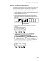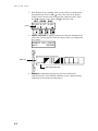
1
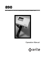
890
AUTOMATIC STRIP READING DENSITOMETER
Operation Manual
Dear Customer:
Congratulations! We at X-Rite, Incorporated are proud to present you with
X-Rite 890 Auto Strip Reading, Color Photographic Densitometer. This
instrument represents the very latest in microcontrollers, integrated circuits,
optics, and display technology. As a result, your X-Rite instrument is a
rugged and reliable instrument whose performance and design exhibit the
qualities of a finely engineered instrument, which is not surpassed.
To fully appreciate and protect your investment, we suggest that you take the
necessary time to read and fully understand this manual. As always, X-Rite
stands behind your instrument with a one year limited warranty, and a dedicated
service organization. If the need arises, please don’t hesitate to call us.
Thank you for your trust and confidence.
X-Rite, Incorporated
i
INTRODUCTION
FCC
This equipment has been tested and found to comply with the limits for a Class
A digital device, pursuant to Part 15 of the FCC Rules. These limits are
designed to provide reasonable protection against harmful interference when
the equipment is operated in a commercial environment. This equipment
generates, uses, and can radiate radio frequency energy and, if not installed
and used in accordance with the instruction manual, may cause harmful
interference to radio communications. Operation of this equipment in a
residential area is likely to cause harmful interference in which case the user will
be required to correct the interference at his own expense.
Canada
This Class A digital apparatus meets all requirements of the Canadian
Interference-Causing Equipment Regulations.
Cet appareil numérique de la classe A respecte toutes les exigences du
Règlement sur le matériel brouilleur du Canada.
NOTE: Shielded interface cables must be used in order to maintain compliance
with the desired FCC and European emission requirements.
CAUTION: Operational hazard exists if AC adapter other than X-Rite SE30-77
(100-240V) is used.
VORSICHT: Betriebsgefahr besteht bei Gebrauch von anderen Adaptern als
X-Rite SE30-77 (100-240 V).
AVISO: No use otro adaptador C.A. que no sea la pieza X-Rite SE30-77 (100240V), por el riesgo de mal funcionamiento del equipo.
ATTENTION: Ne pas utiliser d’adaptateur autre que SE30-77 (100-240V) de XRite au risque de mauvais fonctionnement de l’appareil.
AVVISO: Non usare un altro adattatore C.A. che non è del pezzo X-Rite SE3077 (100-240V), per il rischio di malfunzionamento dell'apparecchio.
The Manufacturer:
Der Hersteller:
El fabricante:
Le fabricant:
Il fabbricante:
X-Rite, Incorporated
4300 44th Street, S.E.
Grand Rapids, Michigan 49512
Declares that:
gibt bekannt:
advierte que:
avertit que:
avverte che:
Densitometer
890
is not intended to be connected to a public telecommunications network.
an ein öffentliches Telekommunikations-Netzwerk nicht angeschlossen werden soll.
no debe ser conectado a redes de telecomunicaciones públicas.
ne doit pas être relié à un réseau de télécommunication publique.
non deve essere connettuto a reti di telecomunicazioni pubblici.
ii
USER INFORMATION
CE DECLARATION
Manufacturer's Name:
Manufacturer's Address:
X-Rite, Incorporated
4300 44th Street, S.E.
Grand Rapids, Michigan 49512
U.S.A.
Model Name:
Model No.:
Densitometer
890
Directive(s) Conformance:
EMC 89/336/EEC LVD 73/23/EEC
WEEE
As of August 13, 2005, X-Rite products meet the European Union – Waste Electrical and
Electronic Equipment (WEEE) directive. Please refer to www.xrite.com for more information on
X-Rite’s compliance with the WEEE directive.
Warning: This is a class A product. In a domestic environment this product may cause radio
interference in which case the user may be required to take adequate measures.
PROPRIETARY NOTICE
The information contained in this manual is derived from patent and
proprietary data of X-Rite, Incorporated. This manual has been prepared
solely for the purpose of assisting in the use and general maintenance of this
instrument.
The contents of this manual are the property of X-Rite, Incorporated and are
copyrighted. Any reproduction in whole or part is strictly prohibited.
Publication of this information does not imply any rights to reproduce or use
this manual for any purpose other than installing and operating the
equipment described herein.
No part of this manual may be reproduced, transcribed, transmitted, stored in
a retrieval system, or translated into any language or computer language, in
any form or by any means, electronic, magnetic, mechanical, optical, manual,
or otherwise, without the prior written permission of an officer of
X-Rite, Incorporated.
This instrument may be covered by one or more patents. Refer to the
instrument for actual patent numbers.
Copyright © 2007 by X-Rite Incorporated
“ALL RIGHTS RESERVED”
X-Rite® is a registered trademark of X-Rite, Incorporated
All other logos, product names, and trademarks mentioned are the property of their respective holders.
iii
INTRODUCTION
LIMITED WARRANTY
X-Rite, Incorporated (“X-Rite”) warrants each instrument manufactured to
be free of defects in material and workmanship (excluding battery pack) for a
period of 12 months. This warranty shall be fulfilled by the repair or
replacement, at the option of X-Rite, of any part or parts, free of charge
including labor, F.O.B. its factory or authorized service center.
This warranty shall be voided by any repair, alteration, or modification, by
persons other than employees of X-Rite, or those expressly authorized by XRite to perform repairs, and by any abuse, misuse, or neglect of the product,
or by use not in accordance with X-Rite’s published instructions.
X-Rite reserves the right to make changes in design and /or improvements to
its products without any obligation to include these changes in any products
previously manufactured. Correction of defects by repair or replacement
shall constitute fulfillment of all warranty obligations on the part of X-Rite.
THIS WARRANTY IS EXPLICITLY IN LIEU OF ANY OTHER
EXPRESSED OR IMPLIED WARRANTIES, INCLUDING ANY
IMPLIED WARRANTY OF MERCHANTABILITY OR FITNESS FOR
ANY PARTICULAR PURPOSE. THIS WARRANTY OBLIGATION IS
LIMITED TO REPAIR OR REPLACEMENT OF THE UNIT RETURNED
TO X-RITE OR AN AUTHORIZED SERVICE CENTER FOR THAT
PURPOSE.
This agreement shall be interpreted in accordance with the laws of the State
of Michigan and jurisdiction and venue shall lie with the courts of Michigan
as selected by X-Rite, Incorporated..
iv
TABLE OF CONTENTS
This manual is organized into eight sections and four appendices. In order to
make the best use of your instrument, it is recommended that you read all
sections and appendices.
SECTION ONE - Getting Started
Unpacking and Inspection __________________________________ 1-1
Packing Drawing and Parts List _______________________ 1-1
Product Description_______________________________________ 1-2
Applying Power _________________________________________ 1-3
User Interface ___________________________________________ 1-4
Channel and Function Menus_________________________ 1-4
Display and Keyswitch Definition _____________________ 1-5
Menu Keys _______________________________________ 1-5
Help Messages ____________________________________ 1-5
Adjusting the Paper Guides_________________________________ 1-6
Strip Measurement Techniques ______________________________ 1-7
Strip Information __________________________________ 1-7
Paper Strip _______________________________________ 1-7
Film Strip ________________________________________ 1-10
Printer Balance Strip _______________________________ 1-10
SECTION TWO - Instrument Calibration
Calibration Information____________________________________ 2-1
Frequency of Calibration ____________________________ 2-1
Auto Calibration Procedure_________________________________ 2-2
Manual Calibration Procedure_______________________________ 2-3
SECTION THREE - Setting System Configuration
Instrument Configuration __________________________________ 3-1
Page 1 Configuration Options ________________________ 3-1
Page 2 Configuration Options ________________________ 3-2
Page 2a Configuration Options _______________________ 3-2
Page 2b Configuration Options _______________________ 3-3
Page 2c Configuration Options _______________________ 3-3
Page 2d Configuration Options _______________________ 3-3
Configuration Setup Procedure _______________________ 3-3
v
INTRODUCTION
SECTION FOUR - Strip Operation
Measuring Strips _________________________________________ 4-1
View Strip Data ___________________________________ 4-3
Manually Transmitting Strip Data____________________________ 4-5
SECTION FIVE - Service and General Maintenance
Repair Information _______________________________________ 5-1
Cleaning the Instrument ___________________________________ 5-2
General Cleaning __________________________________ 5-2
Cleaning the Optics ________________________________ 5-2
Cleaning the Calibration Strip ________________________ 5-3
Replacing the Read Lamp __________________________________ 5-4
Troubleshooting Tips _____________________________________ 5-5
APPENDIX A - Technical Specification
APPENDIX B - Display Messages
APPENDIX C - Term Abbreviations
APPENDIX D - Parts List and Packaging Drawing
APPENDIX E - 890 Instrument Firmware Update
vi
SECTION ONE
Getting Started
This section covers unpacking, inspection, and general set up of your
instrument. Product description, paper guide adjustments, and measurement
techniques are also include.
Section One Contents
•
•
•
•
•
•
Unpacking and Inspection
Product Description
Applying Power
User Interface
Adjusting the Paper Guides
Strip Measurement Techniques
UNPACKING AND INSPECTION
After removing the instrument from the shipping carton, inspect for possible
damage. If any damage occurred during shipping, immediately contact the
transportation company. Do not proceed with installation until the carrier’s
agent has inspected the damage.
Your instrument was packaged in a specially designed carton to assure
against damage. If reshipment is necessary, the instrument should be
packaged in the original carton. If the original carton is not available, contact
X-Rite to have a replacement shipped to you.
Packaging Drawing and Parts List
Check your packaging contents against your packing list and your original
order. Detailed packaging drawing and parts list is included in this manual as
Appendix D.
1-1
SECTION
ONE
PRODUCT DESCRIPTION
The X-Rite 890 automated instruments measures paper, film, and printer
balance control strips. Simply insert the strip into the instrument for
motorized, automatic measurements. Red, green, and blue density data is
sorted for fields such as HD, LD, and Stain, then simultaneously displayed
and transmitted to a minilab printer for analysis.
To accommodate the different size control strips, the instrument has adjustable
paper guides on each side of the control strip entrance. Adjustment is made by
simply sliding the paper guides to the settings displayed for the selected strip.
The instrument communicates through a standard RS-232 interface. If you
wish to remotely control your instrument, you must use the remote control
interface protocol discussed in the RS-232 Interface Manual—available from
X-Rite, Incorporated.
Operating Key llll
Operating Key lll
2 x 16 Character
Display
Operating Key ll
Operating Key l
RS-232 Serial
Interface
Paper Guide
35mm Strip Entrance
Power Input
Paper Guide
1-2
GETTING
STARTED
APPLYING POWER
To apply power to the instrument:
1. Verify that the voltage indicated on the adapter complies with the AC
line voltage in your area. If not, contact X-Rite or your authorized
representative.
2. Insert the small plug from the adapter into the power-input connector on
the instrument.
3. Plug the detachable line cord into the adapter.
4. Plug the line cord into an AC wall receptacle.
IMPORTANT: To extend the life of the internal memory battery, it is
recommended that the instrument remain plugged into AC power. If you are
using a modem, AC power must be applied in order to transmit or receive data.
Detachable Line Cord
Power Input
Adapter
At initial power-up, the instrument performs a “boot memory test.” The
testing sequence is displayed on the instrument screen. If all internal tests are
OK, Page 1 Main Menu displays—see next page.
Testing Program
boot memory...3
2
1
XRite 890 vXXXX
Copyrt 1989—1997
1-3
SECTION
ONE
USER INTERFACE
The 890 instrument incorporates a three page menu system. Menu pages are
displayed by continually pressing keyswitch l (p#) on the instrument. The
first page contains all the predefined control strips. The last two pages
provide access to the instrument setup options and strip measurement data.
Main Menu
•
•
•
pap (paper) - accesses the paper measurement channel. The format
selected remains selected until changed.
film - access the film measurement channel. The format selected remains
selected until changed.
bal (printer balance) - accesses the printer balance measurement channel.
The format selected remains selected until changed.
Function Menus
•
•
•
•
•
view - used to view data of the last strip measured.
xmit (transmit)- used to manually transmit data of the last strip
measured—via RS-232 port.
cal (calibration) - used for calibration.
cnfg (configuration) - used to access system configuration options.
load - for updating the instrument’s firmware (see Appendix E).
MAIN MENU
p1 pap film bal
FUNCTION MENU
p2 view xmit
FUNCTION MENU
p3 cnfg cal load
1-4
GETTING
STARTED
Display and Keyswitch Definition
The characters in the bottom row of the display dictate which function is
selected or which action takes place when a corresponding keyswitch is
pressed. Normally, upper-case lettering in the top row of the display is used
for messages, and lower-case lettering in the bottom row is used for menu
options that are selectable.
Each keyswitch is embossed with identification marks signifying its number.
The left-most key is labeled “I”, center-left key is labeled “ll”, and so on.
Keyswitches that are used to select a function or perform an action are tinted
(grayed) throughout this manual.
MAIN MENU
p1 pap film bal
Messages (top row)
Functions (bottom row)
Keyswitch identification marks
Menu Keys
Keyswitch lll and llll have the word “MENU” printed above them. Pressing
these two keys simultaneously at any location in the menu structure causes
the display to return to page 1 of the main menu.
MAIN MENU
p1 pap film bal
MENU
Press keys simultaneously
Help Messages
Built-in help messages are available for most functions. Help messages are
activated by pressing and holding down a key until the message appears. To
temporarily pause a message, press the key again.
MAIN MENU
p1 pap film bal
PAPer
"pap" key select
MENU
Press and hold keyswitch to see help message
1-5
SECTION
ONE
ADJUSTING THE PAPER GUIDES
To accommodate various size paper strips, the instrument has an adjustable
paper guide on each side of the strip entrance. Each paper guide has a pointer
(triangle) that is aligned with a number on the guide rail. The guide setting
numbers are shown on the instrument display when a paper strip is selected.
The paper guide rail has setting marks that range from “9-30” to the left and
right of the center diamond. Each mark (stop) is 1/10” increment—10 stops
equal one inch. The instrument automatically displays the proper guides
settings for the selected strip (see below).
Instrument Display
30
Paper Guide
20
READ k:RA–4 ALL
18>other
AT<18
10
10
20
30
Pointer
Center Diamond
The paper guides are moved by sliding them to the left or right.
Paper Strip
Center Alignment Line
To accommodate 35mm wide strips, the instrument has a special stationary
guide located above the diamond
Stationary Guide
Film Strip
35mm Slot
35mm Film
1-6
GETTING
STARTED
STRIP MEASUREMENT TECHNIQUES
All control strip types should have at least a 30.5mm (1.25”) leader before the
first measurable patch. However, strips with less than a 30.5mm leader can
also be measured reliably if required. Refer to your Control Strip and
Balance Print Format Guide for leaderless strip measurement procedure.
Supported strip definitions and strip insertion direction information is
available in your Control Strip and Balance Print Format Guide shipped with
your instrument.
Strip Information
•
If a strip becomes “jammed” in your instrument during a measurement,
simultaneously press key lll and key llll labeled “MENU.” This should
cause the instrument to feed-out the strip. If this method does not work,
slowly pull strip out from the front of the instrument.
•
A strips is inserted into the instrument until it rests against the drive
rollers.
•
After a strip is initially inserted into the instrument, a one second delay
occurs before the drive mechanism is activated to allow time for proper
alignment.
•
Due to the amount of variation in printer balance strips, no guide setting
numbers appear in the display in the printer balance categories.
•
Due to the configuration of the instrument drive mechanism, 16mm wide
film control strips cannot be measured.
•
The instrument does measure strips that are creased.
Paper Strip
When a particular paper strip is selected, one or both of the displayed paper
guide setting numbers flash. If only one guide setting number is flashing, this
indicates the guide that the strip rests on first when measuring. In most cases
this only occurs on a strip that required multiple passes such as, Fuji CP-21.
Both guide setting numbers flash on single pass strips.
Indicates CYN patches are
read one the first pass
Indicates ALL patches are
read on one pass
Indicates strip type
Single
Pass
Indicates strip type
READ k:RA–4 ALL
18>other
AT<18
Both guide setting number
flash, indicating a single
pass strip
READ f:CP21 CYN
26>other
AT<17
Multi
Pass
One guide setting number
flashes, indicating strip
placement on this guide first
1-7
SECTION
ONE
Single Pass
Single pass strips require the strip to be inserted into the instrument once.
In this example, the strip—Kodak RA4—can be inserted in either direction.
Refer to your Control Strip and Balance Print Format Guide for information
on all strips supported.
30
20
10
10
20
READ k:RA–4 ALL
18>other
AT<18
30
Indicates ALL patches are measured
Multi Pass
Typically, a multi pass strip requires three pass through the instrument to
obtain measurement data. The instrument displays what color patches are
measured and what guide is used to insert the strip from.
In this example, the cyan—Fuji CP21—row of patches is measured first,
followed by the magenta and yellow. Refer to your Control Strip and
Balance Print Format Guide for information on strip insertion direction.
20
20
10
10
PASS ONE
30
READ f:CP21 CYN
26>other
AT<17
30
Indicates cyan patches are measured
Guide number flashes, indicting
strip positioning
1-8
GETTING
STARTED
20
20
10
10
PASS TWO
30
READ f:CP21 MAG
26>other
AT<17
30
Indicates magenta patches are
Guide number flashes, indicting
strip positioning
20
20
10
10
PASS THREE
30
READ f:CP21 YEL
26>other
AT<17
30
Indicates yellow patches are measured
Guide number flashes, indicting
strip positioning
The third pass requires the strip to be rotated to take the measurement.
1-9
SECTION
ONE
Film Strip
The Film category requires that the film strip be inserted into the 35mm slot
located above the center diamond. In this example—Kodak C41—the strip
can be inserted in either direction. Refer to your Control Strip and Balance
Print Format Guide for information on all strips supported.
20
10
10
20
30
READ k:C41 ALL
AT 35mmSlot other
30
Indicates ALL patches are measured
Indicates the strip is inserted
into the 35mm slot
Printer Balance Strip
The Printer Balance category in the instrument has five basic strip formats:
Wht-Eye, Blk-Eye, No-Ring, K:3510, and Small-BE. Each category has six
print options to choose from. Refer to your Printer Balance and Control
Guide for detailed information on all aspects of the printer balance strips.
Due to the amount of variation between printer balance strips, no guide
setting numbers appear in the display.
In this example—Blk-Eye, UNO 1-Pass—the Under patch is inserted first.
OVER
N
NORMAL
U
UNDER
Indicates the strip type to measure
1-10
O
20
10
10
20
30
READ Blk–Eye UND
UNO 1–Pass other
30
Indicates the under patch is inserted first
SECTION TWO
Instrument Calibration
This section covers the calibration procedures for your instrument.
Section Two Contents
•
•
•
Calibration Information
Auto Calibration Procedure
Manual Calibration Procedure
CALIBRATION INFORMATION
The instrument has two types of calibration procedures available, automatic
and manual. AUTO is the standard method of calibration. If you want your
instrument to measure the same as another densitometer that has the same
response, you would use the MANUAL procedure. When the instrument
automatically calibrates, the density values are set precisely to that of the
paper measured for reflection, and to no film (air) for transmission.
The instrument has many self checking algorithms built in to verify the
accuracy of calibration. If you wish to maintain accuracy verification, we
suggest that you obtain a C41 reference strip and a paper reference strip.
Measure each strip and record the density values. Place the strips in an
envelope and store them in a dry, cool environment. Periodically, measure
them to verify accuracy. Note, reference strips tend to drift in density with
time, consult the manufacturer's specifications for expected density changes.
If your Auto-Cal strip gets ruined or worn, you can order a replacement from
X-Rite or your local dealer. Order Part Number 880-100.
Frequency of Calibration
Under normal operating conditions, the instrument should be calibrated
once a week or when instrument displays a message regarding calibration.
2-1
SECTION
TWO
AUTO CALIBRATION PROCEDURE
NOTE: Make sure the Auto-Cal strip is free of dust, dirt, and smudgemarks.
Refer to Section Eight for cleaning procedure. Handle cal strip by the edges.
1. Press key lll (cal) located on Function Menu page (p3) to initiate calibration.
FUNCTION MENU
p3 cnfg cal load
•
The instrument screen momentarily displays CALIBRATING
TRANSMISSION during automatic transmission calibration
(reading air), and CALIBRATING MOTOR SPEED.
CALIBRATING
TRANSMISSION
•
CALIBRATING
MOTOR SPEED...
After this is complete, the instrument screen asks you to INSERT CAL
STRIP. Make sure the key labeled AUTO is upper-case lettering. If not,
press key l (AUTO) to toggle to upper-case. Note, lower-case lettering
denotes manual calibration (MANUAL) is activated.
INSERT CAL STRIP
manual
AUTO
Auto must be
displayed in uppercase. If not, press
key l to toggle on.
10
2. Insert the designated end of the Auto-Cal strip into the 35mm slot until it
comes to rest against the drive rollers.
X-RITE Auto-Cal Strip P/N 880-100 Patent Pending
SERIAL #: XXX-XXX
35mm slot
CAL R= 0.04 G= 0.07 B= 0.08
10
INSERT THIS END
Note insertion direction
•
READING is momentarily displayed on the screen followed by
calibration density values. Auto calibration is now complete and the
instrument screen returns to the Main menu.
NOTE: If UNRECOGNIZEABLE STRIP momentarily appears on the screen
when a cal strip is measured, the strip may be dirty—refer to Section Eight
for procedure. However, if cleaning the strip does not resolve the problem,
enter calibration manually then re-measure the strip.
2-2
INSTRUMENT
CALIBRATION
MANUAL CALIBRATION PROCEDURE
The manual calibration procedure is used to correlate the low densities of the
instrument to another densitometer. Doing this allows the instrument to
measure approximately the same as another densitometer that has Status A
reflection response, and has been calibrated to ANSI Standards.
1. Using the instrument's own reference, calibrate the densitometer that you
want this instrument to correlate with.
2. Using the same densitometer, measure the white area below the first
black bar on the X-Rite Auto-Cal strip and record the Red, Green, and
Blue values.
X-RITE Auto-Cal Strip P/N 880-100 Patent Pending
SERIAL #: XXX-XXX
CAL R= 0.04 G= 0.07 B= 0.08
INSERT THIS END
Measure here using
other instrument.
3. Press key lll (cal) located on Function Menu page (p3) to initiate
calibration.
FUNCTION MENU
p3 cnfg cal load
•
The instrument screen momentarily displays CALIBRATING
TRANSMISSION during automatic transmission calibration
(reading air), and CALIBRATING MOTOR SPEED.
CALIBRATING
TRANSMISSION
CALIBRATING
MOTOR SPEED...
4. After this is complete, the instrument screen asks you to INSERT CAL
STRIP. DO NOT INSERT STRIP AT THIS TIME.
Press key llll (manual) to advance to calibration reference values screen.
INSERT CAL STRIP
manual
AUTO
2-3
SECTION
TWO
5. Enter the Red, Green, and Blue values you previously recorded into the
designated fields. Press key llll (→) to move the cursor to the desired
location, and to advance to the next step after editing the values. Press
key ll (↑) to increase value and key lll (↓) to decrease value.
RED GREEN BLUE
Cursor
0.04
_
0.07 0.08
→
CAL R ↑
↓
6. INSERT CAL STRIP re-appears on the screen. Insert the designated end
of the Auto-Cal strip into the 35mm slot until it comes to rest against the
drive rollers.
10
INSERT CAL STRIP
auto
MANUAL
X-RITE Auto-Cal Strip P/N 880-100 Patent Pending
SERIAL #: XXX-XXX
35mm slot
CAL R= 0.04 G= 0.07 B= 0.08
10
INSERT THIS END
Note insertion direction
•
READING is momentarily displayed on the screen followed by
calibration density values. Manual calibration is now complete and the
instrument screen returns to the Main menu.
2-4
SECTION THREE
Setting System Configuration
The system configuration allows you to customize your instrument to meet
your requirements. The configuration should be viewed and edited as needed
before any measurements are taken.
Section Three Contents
•
Instrument Configuration
INSTRUMENT CONFIGURATION
The configuration functions are contained in two main screen pages. Page
one contains setup functions for instrument beeper tone, and network. Page 2
is broken down into five menu pages, four of which are submenus—p2a,
p2b, and so on. Page two menus contain serial interface control options.
Descriptions for all configuration options are listed below, followed by set up
procedures.
Page 1 Configuration Options
TONE
Use to adjust the instruments beeper volume. Available settings are: OFF,
SOFT, and LOUD.
NET (Networking)
Enables the instrument to automatically send and receive data via the modem
at a predetermined time that is selected by the QC computer. Available
settings are: OFF, OUT, IN, and I&O.
•
•
•
•
OFF - disables the instrument from automatically sending or receiving data.
OUT - enables unit to call out via modem from QC host.
IN - enables unit to answer incoming call on modem from QC host.
I&O - enables both automatic transmission and reception of data.
3-1
SECTION
THREE
Page 2 Configuration Options
IO preset
This options provides several QC system selections. All the necessary
RS-232 interface parameters are automatically set when a predefined I/O
preset is selected. A “CUSTOM” preset is available which allows you
manually set all available I/O options. Below is a chart that contains all
available I/O presets and their parameter settings.
NOTE: Certain parameters are mandatory for the I/ O preset and cannot be
changed. They are labeled with an “L” for locked. Other parameters are not
considered mandatory and are labeled with a “U” for unlocked. Finally,
parameters that remain unchanged from previous settings—and can be
changed—are shown as an asterisk (*).
I/O Preset
REPORT
SPRD-SHT
k:TNetA
k:TNetXT
K:C.A.P.
k:SYS25-75
f:TECOM
c:I/O#1
c:I/O#2
MITSY#1
MITSY#2
NORITSU
n:QSSnet
n:Micro
kn:Net
a:LC2000
CUSTOM
Windense
Kodatel
Sienna
RCI
Off
*
Off (L)
Off (L)
Off (L)
Off (L)
Off (L)
On (L)
On (U)
Off (U)
Off (L)
Off (L)
Off (U)
*
TTL (U)
Off (U)
#
On (U)
On (U)
On (U)
PIN5
*
*
Off (L)
CTS(L)
CTS(U)
CTS(L)
Off (L)
Off (L)
Off (U)
Off (U)
Off (L)
CTS(U)
Off (U)
*
Off (U)
Off (U)
#
Off (U)
Off (U)
Off (U)
XON
*
*
Off (L)
Off (L)
Off (L)
Off (L)
Off (U)
Off (L)
Off (U)
Off (U)
On (U)
Off (L)
Off (U)
*
Off (U)
Off (U)
#
Off (U)
Off (U)
Off (U)
DPT
On (L)
*
Off (L)
Off (L)
Off (U)
Off (L)
Off (U)
Off (U)
Off (U)
Off (L)
Off (L)
Off (L)
Off (U)
*
Off (U)
Off (U)
#
Off (U)
Off (U)
On (U)
COMP
On (L)
Off (L)
On (L)
On (L)
On (U)
On (L)
Off (U)
On (U)
On (U)
Off(L)
Off(L)
On (L)
Off (U)
*
On (U)
On (U)
#
On (U)
On (U)
On (U)
ALF
On (U)
*
On (L)
On (L)
On (U)
On (L)
Off (U)
On (U)
On (U)
Off(L)
Off(L)
On (L)
Off (U)
*
Off (U)
On (U)
#
Off (U)
Off (U)
On (U)
DEL
Off (L)
*
On (L)
Off (L)
Off (L)
Off (L)
Off (U)
On (U)
On (U)
Off (U)
Off (L)
Off (L)
Off (U)
*
Off (U)
On (U)
#
Off (U)
Off (U)
Off (U)
AXMT
Off (U)
On (L)
On (L)
On (L)
On (L)
On (L)
On (U)
On (L)
On (U)
On (U)
On (L)
On (L)
On (U)
*
Off (U)
On (U)
#
On (U)
On (U)
On (U)
BAUD
*
*
300(L)
*
9600(L)
*
1200(U)
9600(L)
9600(U)
300(L)
300(U)
2400(U)
2400(U)
*
2400(U)
1200(U)
#
9600 (U)
9600 (U)
4800 (U)
k: (Kodak), f: (Fuji), c: (Copal), kn: (Konica), n: (Noritsu), a: (Agfa)
Page 2a Configuration Options
RCI (Remote Control Interface)
Controls the ability of the instrument to be operated remotely. Available
settings are: OFF, ON, TTL.
•
•
•
OFF - sets the instrument into a receive mode at which time the instrument
receives data.
ON - enables data to be received via RCI command.
TTL (Time Tagged Log) - causes all data received into the serial port to be
placed into the log buffer with a time stamp.
PIN5
Determines the status of the handshaking input on Pin 5 of the RS-232 I/O port.
Pin 5 may be interpreted as BUSY, CTS (clear-to-send), or OFF (ignored).
3-2
SETTING
SYSTEM
CONFIGURATION
XON
When set to On (XON), this enables bi-directional transmit On/Off protocol.
When set to Off (xon), the instrument ignores XON/OFF codes. Note, usage
is limited to output at this point.
Page 2b Configuration Options
DPT (Decimal Point)
Controls the decimal point availability during data output. When off (dtp), no
decimal is output with data. When on (DTP), decimal points are included
with the output data.
COMP (Compact)
Varies the output format of the data. When off (comp), data for each color is
delimited with a carriage return—or CR LF if ALF is enabled. When on
(COMP), a space and delimiter is transmitted after each set of RGB data values.
ALF (Automatic Line Feed)
Controls the line feed availability during data output. When off (alf), no line
feed is output with data. When on (ALF), a line is included with the output
data.
Page 2c Configuration Options
DEL (Delay)
Controls a transmitted delay between each set if RGB data output. When off
(del), no delay is sent between each set of RGB data. When on (DEL), a one
second delay is sent between each set of RGB data.
AXMT (Automatic Transmit)
Controls automatic transmission of data after a measurement. When off
(axmt), no data is transmitted out the I/O port after a measurement. When on
(AXMT), data is automatically sent out the I/O after a measurement.
Page 2d Configuration Options
BAUD (Rate)
Determines the data output rate (characters per second) of the I/O port.
Available settings are: 110, 300, 600, 1200, 2400, 4800, and 9600.
LOCK
Controls the ability to change the configuration options. When off (lock),
configuration options are available for change. When on (LOCK),
configuration options cannot be changed. Note, an additional step is required
to change this option, refer to the following procedure for details.
Configuration Setup Procedure
•
Options that toggle on and off display in upper-case (on) or lower-case
(off). For example, COMP = on and comp = off.
3-3
SECTION
THREE
•
You can save and exit the configuration at anytime without editing all
options. This is accomplished by simultaneously pressing key l and
key ll when SAVE is displayed in the screen.
•
Configuration can be exited at anytime without saving changes by
simultaneously pressing key lll and key llll (MENU keys).
1. Press key ll (cnfg) located on the Function Menu screen (p3) to enter
Page1 Configuration screen.
FUNCTION MENU
p3 cnfg cal load
2. Page 1 Configuration Screen
• Press key lll (TONE) to page through and select a beeper tone option
(OFF, SOFT, and LOUD).
• Press key llll (NET) to page through and select a networking option
(OFF, OUT, IN, and I&O. Note, only set if network modem is used.
• After editing Page 1 Configuration options, press key l (P1) to advance
to Page 2 Configuration screen.
SAVE
P1
CNFG
TONE NET
3. Page 2 Configuration Screen
• Press key ll or key lll (IOpreset) once to enter I/O preset menu.
CNFG
P2 IOpreset
•
•
•
Press key ll or key lll to page through and select a preset options
(CUSTOM, REPORT, SPRD-SHT, k:TNetA, etc.).
After selecting I/O preset option, press key llll (P2) to load preset and
advance to Page 2a Configuration screen.
If you do not want to load a preset, press key l (P2) to advance to
Page 2a Configuration screen.
P2
3-4
CNFG
CUSTOM load
SETTING
SYSTEM
CONFIGURATION
4. Page 2a Configuration Screen
• Press key ll (RCI) to page through and select a remote control interface
option (OFF, ON, TTL).
• Press key lll (PIN5) to page through and select a handshake option (OFF,
BUSY, and CTS).
• Press key llll (XON) to select bi-directional transmit On/Off protocol
option. Each key depression alternates between xon (off) and
XON (on).
• After editing Page 2a Configuration options, press key l (P2a) to advance
to Page 2b Configuration screen.
CNFG
SAVE
P2a RCI PIN5 XON
5. Page 2b Configuration Screen
• Press key ll (DPT) to select decimal point output option. Each key
depression alternates between dtp (off) and DPT (on).
• Press key lll (COMP) to select data output format option. Each key
depression alternates between comp (off) and COMP (on).
• Press key llll (ALF) to select automatic line feed option. Each key
depression alternates between alf (off) and ALF (on).
• After editing Page 2b Configuration options, press key l (P2b) to
advance to Page 2c Configuration screen.
CNFG
SAVE
P2b DPT COMP ALF
6. Page 2c Configuration Screen
• Press key ll (DEL) to select delay option. Each key depression alternates
between del (off) and DEL (on).
• Press key lll (AXMT) to select automatic transmission option. Each key
depression alternates between axmt (off) and AXMT (on).
• After editing Page 2b Configuration options, press key l (P2b) to
advance to Page 2c Configuration screen.
CNFG
SAVE
P2c DEL AXMT
3-5
SECTION
THREE
7. Page 2d Configuration Screen
• Press key ll (baud) to page through and select a baud rate option (300,
600, 1200, 2400, 4800, 9600, 19200, 38400, 57600).
• Insert a piece of paper into the paper slot at least 1-¼” to activate the read
switch—heavy paper or film works best. Press key llll (lock) to select
lock option. Each key depression alternates between lock (off) and
LOCK (on). A “LOCK” selection (padlock icon closed) prevents any
option changes from occurring .
• After editing Page 2d Configuration options, simultaneously press
key l (P2d) and key ll (baud) to save configuration settings. Pressing key
l (P2d) alone causes Page 1 Configuration screen to reappear.
CNFG
SAVE
P2d baud
lock
3-6
Padlock icon displays “closed”
when options are locked.
SECTION FOUR
Strip Operation
It is important to make sure control strips and reference strips used are from
the same batch number.
Always inspect control strips for damage before measuring. Care must also
be taken when handing strips. Fingerprints on measurable patches can affect
density values.
IMPORTANT! When inserting strips into the instrument, there should be at
least a 30.5mm (1.25”) leader before the outside edge of the first measurable
target or the first target may not be detected. For information on measuring
leaderless strips (30.5mm), refer to your Control Strip and Balance Print
Format Guide, Section Five.
Section Four Contents
•
•
Measuring Strips
Manually Transmitting Strip Data
MEASURING STRIPS
Refer to your Control Strip and Balance Print Format Guide to located your
control strip for proper insertion direction.
1. Select strip channel from Main Menu page 1.
MAIN MENU
p1 pap film bal
2. If format displayed is not correct, press key llll (other) to select correct
strip format.
READ k:RA—4 ALL
AT <18 18> other
4-1
SECTION
FOUR
3. Measure strip
• For paper strips, adjust the paper guides according to the number
displayed on the screen. If multiple pass, note what color is to be
measured first. Insert strip until it comes to rest against the drive rollers.
•
For film strips, note insertion direction and insert strip into the 35mm
slot until it comes to rest against the drive rollers.
•
For printer balance strips, note insert direction and center bull’s-eye
over middle diamond. Slide paper guides next to strip and insert strip
until it comes to rest against the drive rollers.
Center Diamond
Paper Guide
20
30
10
35mm Slot
•
10
20
30
Paper Guide
The densitometer indicates that processing is taking place and the
measurement status. If a paper strip is measured that has multiple passes,
the display indicates the pass to insert.
PROCESSING...
PASS #1 of 1 OK!
NOTE: If INVALID READING, UNRECOGNIZABLE STRIP, or BUFFER
OVERFLOW messages display after a measurement, re-read strip. If the same
message appears after re-reading strip, refer to Appendix B of this manual.
•
Transmitting Data momentarily appears in the display screen (if auto
transmit is enabled in Configuration Options), indicating measurement
data is being transmitted out the I/O port.
TRANSMITTING
DATA
•
The instrument screen displays the RGB measurement results. Refer to
next page for procedure to view field results.
r.rr g.gg
Stain
4-2
b.bb
exit
STRIP
OPERATION
View Strip Data
Control strip data consists of the “actual” values measured by the instrument.
Control strip data is viewed after a strip measurement or by selection from
the Main Menu (p2).
Viewing Data after Control Strip Measurement
1. Press key l (Stain) to page through RGB data fields of the strip.
2. After viewing data, press key llll (exit) to exit.
Red Green Blue
0.29 0.34 0.54
Stain
exit
Viewing Control Strip Data from View Menu
1. Press key ll (view) located on Function Menu page (p2) to enter View
Menu screen.
FUNCTION MENU
p2 view xmit
2. Press key ll (pap), key lll (film), or key llll (bal) to select strip category.
VIEW MENU
pap film bal
3. Press key ll or key lll (Stain) to page through RGB data fields of the
strip. After viewing data, press key llll (exit) to exit to the View Menu, or
simultaneously press key lll and key llll (MENU) to exit to the Main
Menu.
Red Green Blue
0.29 0.34 0.54
VIEW> Stain exit
NOTE: CHANNEL IS EMPTY appears in the display if no control strip data
is available to view.
4-3
SECTION
FOUR
MANUALLY TRANSMITTING STRIP DATA
The manual transmit function allows you to transmit data for the last
measurement taken in the paper, film, and printer balance categories.
1. Press key lll (xmit) located on Main Menu page (p2) to enter Xmit Menu
screen.
MAIN MENU
p2 view xmit
2. Press key ll (pap), key lll (film), or key llll (bal) to select strip category.
XMIT MENU
pap film bal
NOTE: CHANNEL IS EMPTY appears in the display if no control strip data
is available in the selected channel.
3. Transmit strip data.
• Press key l (xmit) to transmit all strip data. (“xmit” changes to upper-case
during transmission.)
• After transmitting data, press key llll (exit) to exit to the Xmit Menu, or
simultaneously press key lll and key llll (MENU) to exit to the Main
Menu.
film ( k:C41 )
XMIT (All) exit
4-4
SECTION FIVE
Service and General
Maintenance
This section covers repair information, cleaning, general maintenance, and
troubleshooting tips for your instrument.
Section Five Contents
•
•
•
•
Repair Information
Cleaning the Instrument
Replacing the Read Lamp
Troubleshooting Tips
REPAIR INFORMATION
The X-Rite 890 is covered by a one-year limited warranty and should be
referred to the factory or an authorized service center for repairs within the
warranty period. Attempts to make repairs within this time frame may void
the warranty.
X-Rite provides a factory repair service to their customers. Because of the
complexity of the circuitry, all repairs should be referred to the factory or an
authorized service center (call: 1-888-826-3044).
X-Rite will repair any 890 instrument past warranty. Shipping cost to the
factory or authorized service center shall be paid by the customer, and the
instrument shall be submitted in the original carton, as a complete unaltered
unit.
5-1
SECTION
FIVE
CLEANING THE INSTRUMENT
Your instrument requires very little maintenance to achieve years of reliable
operation. However, to protect your investment and maintain reading
accuracy, a few simple cleaning procedures should be performed from time
to time.
General Cleaning
Whenever required, the exterior of the instrument may be wiped clean with a
cloth dampened in water or a mild cleaner.
NOTE: DO NOT use any ketone solvents to clean the unit, this will cause
damage to the cover.
Cleaning the Optics
The optics and drive wheel assembly should be cleaned once a week in
normal environments, and more often in dirty or dusty environments.
1. Carefully lift instrument and insert tube from canned air into “front” strip
insertion slot.
2. With back and forth motion, spray clean, dry air from one side to the
other—do this several times. This should remove any accumulated dust
and lint from the optics and wheel assembly.
WARNING: DO NOT invert cans that use freon as a propellant, doing so
could cause damage to the optics assembly.
5-2
SERVICE
AND
GENERAL
MAINTENANCE
Cleaning the Calibration Strip (Part Number 880-100)
The Auto-Cal strip can be cleaned with a mild soap detergent, and wiped dry
with a clean, lint-free cloth. You must let the calibration strip dry completely
before taking a calibration measurement.
DO NOT clean below the bottom triangle. The attached label is not coated
and smears when moisture is applied. DO NOT get fingerprints on any
portion of the strip, handle by the edge.
X-RITE Auto-Cal Strip P/N 880-100 Patent Pending
INSERT THIS END
DO NOT CLEAN
BELOW THIS LINE!
SERIAL #: XXX-XXX
CAL R= 0.04 G= 0.07 B= 0.08
5-3
SECTION
FIVE
REPLACING THE READ LAMP (PART NUMBER 880-07)
NOTICE: New lamp may appear bent, DO NOT attempt to straighten.
1. Remove four screws (2) securing the bottom cover (3) with a phillipshead screwdriver. Leave bottom cover (3) on unit.
2. Holding top (1) and bottom (3) covers in place, turn unit over so it rests
on the bottom cover (3). Remove top cover (1).
3. Locate optics assembly (4) and remove screw and washer (5) in the
middle of lamp assembly P.C.B. (6).
4. Lift out old lamp assembly (6) and discard.
5. Install new lamp assembly (6) by carefully inserting lamp (6) into
housing (7) and lamp pins (8) into lamp connector. Press down gently to
make sure connector pins (8) are properly seated.
6. Secure lamp screw and washer (5) in place.
7. Carefully clean any dust or plastic chips off circuit board and top cover (1)
using moisture free compressed air. Place top cover back on instrument.
8. Holding top and bottom covers in place, turn unit over so that it rests on
top cover (1).
9. Remove bottom cover (3). Clean circuit board and bottom cover (3) with
compressed air, then place bottom cover (3) back on instrument.
10. Secure bottom cover (3) to instrument with four screws (2) using a
phillips-head screwdriver.
1
5
6
8
4
7
3
2
5-4
SERVICE
AND
GENERAL
MAINTENANCE
TROUBLESHOOTING TIPS
Reflection measurement incorrect:
•
Recalibrate instrument.
•
Clean reflection cal strip or replace if bad.
•
Replace read lamp.*
•
Contact X-Rite or Authorized Service Center.
Transmission measurement incorrect:
•
Recalibrate instrument.
•
Replace read lamp.*
•
Contact X-Rite or Authorized Service Center.
Transmission and Reflection measurement incorrect:
•
Recalibrate instrument.
•
Replace read lamp.*
•
Contact X-Rite or Authorized Service Center.
Measurements drift:
•
Recalibrate instrument.
•
Replace read lamp.*
•
Contact X-Rite or Authorized Service Center.
Unit will not calibrate:
•
Clean or replace cal strip.
•
Read lamp not working.
•
Replace read lamp.*
•
Contact X-Rite or Authorized Service Center.
Measurements unrepeatable/incorrect:
•
Re-insert strip.
•
Use different strip.
•
Contact X-Rite or Authorized Service Center.
* The instrument has a failure monitor that in most cases automatically
indicates when the read lamp requires replacement.
5-5
SECTION
5-6
FIVE
APPENDIX A
Technical Specifications
Transmission Process Control
Film Width
35mm fixed slot or 1.4–6.0in. adjustable
Measurement Speed
1.1 to 1.4 in./sec. (1.2 in./sec. typical)
Spectral Response
Status M
Density Range
0–4.0D
Density Accuracy
±.02D (0–3.0D), ±1% (3.1–3.4D)
±3% (3.5–4.0D)
Density Repeatability
±.01D (0–3.0D)
Control Strip Measurement Area 0.375” (length) x 0.5” (wide) minimum
Reflection (paper) Process Control and Printer Balance
Paper Width
1.4–6.0in. adjustable slot
Measurement Speed
1.3in./sec.
Control Strip Measurement Area 0.375” L x 0.5” W minimum
Printer Balance Measuring Area
0.75” diameter minimum
Spectral Response
Status A
Density Range
0–2.5D
Density Accuracy
±.02D
Density Repeatability
±.01D
General Specifications
AC Adapter
12VDC @ 0.7amp
115VAC (P/N SE30-61)
230VAC (P/N SE30-62)
Instrument Dimensions
7.2” W x 6.0” D x 2.75” H
(182.8mm W x 152.4mm D x 69.mm H)
Specifications and design subject to change without notice.
A-1
APPENDIX
A-2
A
APPENDIX B
Error Messages
Below is a list of typical error messages that can appear on your instrument’s
display screen. If any error messages listed, or not listed should appear, make
a note of it and take the appropriate steps to try to correct it. If an error
message is consistently displayed, contact X-Rite or an authorized service
center.
Message
Reason
Possible Cause
Solution
INVALID READING PLEASE RE-READ!
Unit did not
recognize strip.
Wrong strip selection.
Select correct format.
Strip did not have a
30.5mm (1.2”) leader
before first target.
Use strip with leader or refer
to the Control Strip & Balance
Print Format Guide for
leaderless strip insertion.
Refer to your Control Strip
and Balance Print Format
Guide for insertion direction.
Calibrate instrument, Sec. 2.
Make sure measurement
patches are centered with
diamond and center line.
Usually setting the paper
guides to the numbers
indicated on the display takes
care of the problem. Make
sure strip feed straight through
unit and does not curve toward
one side.
Process and then measure a
new strip.
or
UNRECOGNIZABLE
STRIP
or
BUFFER OVERFLOW
(during measurement)
Strip not inserted in the
correct direction.
Unit needs calibration
Measurement region
not aligned with center
diamond, or strip not
tracking properly.
One or more
measurement patches
are cloudy, have
excessive gradients, or
have flecks.
NOTE: If first read causes invalid error message, try
re-reading strip again. Measurement tolerances across the
patch are opened slightly on second read.
Motor drive roller
Remove restraint/obstruction
slippage due to restraint or dry drive rollers with air.
or obstruction, or
contamination of rollers
from reading wet strips.
Lamp failure (weak or
Perform transmission
bad).
calibration to test lamp, Sec. 2.
B-1
APPENDIX
B
Message
Reason
Possible Cause
UNRECOGNIZABLE
AUTO-CAL STRIP!
Unit did not feed
consistently.
Strip inserted in
Insert strip correctly, Sec. 1.
backwards or upsidedown.
Cal strip is dirty.
Clean cal strip, Sec. 8.
Strip path is blocked by Clean strip path, Sec. 8.
debris keeping cal strip
from feeding properly.
Motor drive roller
Remove restraint/obstruction
slippage due to restraint or dry drive rollers with air. IF
or obstruction, or
problem persists, return unit
contamination of rollers for service.
from reading wet strips.
Strip was pulled out
DO NOT pull on strip during
from back during
measurement.
calibration.
Motor brush wear.
Return unit for service.
NOTE: If motor error message constantly displays, unit
should be returned for proper service.
Recalibrate unit, Sec. 2.
(during reflection cal)
STRIP RESTRAINED
RE-INSERT STRIP!
Cal strip did not
feed consistently.
(during reflection cal)
WARNING MOTOR
ERROR!
Unit senses motor
abnormality.
(during reflection cal)
PRESET MEMORY
PLEASE CALIBRATE
(during power-up)
WARNING LAMP
MARGINAL!
(during trans cal)
WARNING REPLACE
LAMP
(during trans cal)
B-2
Memory data
detected in unit is
not valid.
Lamp output is
less than 50% of
its peak intensity
(but still able to
read).
Lamp output is
less than required
intensity.
Measurement
accuracy of unit is
questionable at
this point.
Solution
Lamp has aged close to
end of its useful life.
Order new lamp. Replace at
convenient time.
Useful lamp life has
expired.
Replace lamp immediately,
Sec. 8.
APPENDIX C
Term Abbreviations
ALF
Automatic Line Feed
ALL
Strip is one pass and may be read in either direction (strip measurement mode)
AXMT
Automatic Transmit
bal
Printer Balance
baud
Varies unit of data transmission speed.
BLK
Black patch must be read first (strip measurement mode)
cal
Calibration
c:I/O#1
Copal, I/O #1
c:I/O#2
Copal, I/O #2
cnfg
Configuration
COMP
Compact
CTS
Clear to Send
CYN
Cyan patch must be read first (strip measurement mode)
def
Default
del
Delete
DEL
Delay (in configuration)
DPT
Decimal Point
f:TECOM
Fuji, Tecom System
HD
High Density patch must be read first (strip measurement mode)
k:C.A.P.
k:SYS
2
7
5→ 5
Kodak, Create a Print
Kodak, Systems 25 through 75
k:TNetA
Kodak, Technet A
k:TNetXT
Kodak, Technet XT
LANG
Language
MIN
Minimum Density patch must be read first (strip measurement mode)
NRM
Normal patch must be read first (strip measurement mode)
NUO 1-Pass
Normal/Under/Over in 1 pass
pap
Paper
PIN5
Pin5 of RS232 port can be set to Off, Busy, or CTS
p1 through p3
Page #1 through Page #3
p2a through p2d
Page #2a through Page #2d
C-1
APPENDIX
C
Q.C.
Quality Control
RCI
Remote Control Interface
SPRD-SHT
Spread Sheet
UND
Under patch must be read first (strip measurement mode)
UNO 1-Pass
Under/Normal/Over in 1 pass
UNO 3-Pass
Under/Normal/Over in 3 passes
xmit
Transmit
YEL
Yellow patch must be read first (strip measurement mode)
↑
Increase amount
↓
Decrease amount
→
Advances cursor
C-2
APPENDIX D
Parts List and
Packaging Drawings
Parts List
D-1
APPENDIX
D
Packaging Drawing
D-2
APPENDIX E
890 Instrument
Firmware Update
The instrument’s firmware is upgraded using Interface Cable P/N SE108-70 and
DB Adapter P/N 881-71, both available from X-Rite.
The following items are required to perform a 890 instrument firmware update:
•
•
•
•
Computer with an available serial port
890 instrument with AC adapter
Update firmware disk
Interface cable (P/N SE108-70) and DB25 adapter (P/N 881-71)
NOTE: Computer screen savers must be disabled during the update
procedure. Once the update has been started, the old firmware
version is permanently erased.
Step 1 Cabling Connection Procedure
•
Insert one end of the interface cable P/N SE108-70 into the I/O port on the
instrument. Modular connector only inserts in one direction.
•
Insert the other end of the interface cable into the DB25 Adapter P/N 881-71.
•
Attach the DB25 adapter to an available “RS-232” I/O port on the computer.
890 Instrument
I/O Serial Port
Interface Cable P/N SE108-70
DB25 Adapter P/N 881-71
E-1
APPENDIX E
Step 2 Setting Instrument to Receive Update
•
Apply AC power to the instrument.
NOTE: Make sure modem baud is set to "57.6K." To check baud, from P3
Function menu, press "Load" key, and then press "cfg" key. Next press "mod"
key, and then press "baud" key. Adjust baud rate if required.
•
Enter the Load Menu by pressing key ll (netwk) on page 3 (p3) Function
Menu.
•
Press key lll (load), Waiting for Host is displayed.
Step 3 Firmware Update Procedure
If you are running DOS under Windows 3.x, you may need to exit Windows to run the
Loader program reliably. You can open an MS DOS window using Win95 or NT.
•
Insert 3-1/2" Update disk into your computer 3-1/2" drive.
•
Change DOS prompt to appropriate drive (A or B).
•
Type: 89X and press [ENTER] key. The program now establishes
communication with the instrument and begins update.
•
After the firmware is updated the unit goes through a normal startup routine.
•
Firmware update is now complete, remove disk and cabling.
Main Menu Fail Message
A Main Menu Fail message will appear on the instrument display if an interruption
in communication occurred during the update. Possible cause for this message is a
power failure, cabling disconnect, etc. When this occurs, the instrument can only be
set to the Waiting for Host mode from the Loader menu. Refer to procedure that
follows.
•
•
•
E-2
From the Main Menu Fail display, press key llll (ok). The instrument displays
the Loader menu.
Press key III (load) and then press key IIII (recv) on Select Function menu.
Waiting for Host is re-displayed on the instrument.
Continue with Step 3.
Corporate Headquarters - USA
4300 44th Street SE
Grand Rapids, Michigan 49512
Phone 1 800 248 9748 or 1 616 803 2100
Fax 1 800 292 4437 or 1 616 803 2705
Corporate Headquarters - Europe
Althardstrasse 70
8105 Regensdorf
Switzerland
Phone (+41) 44 842 24 00
Fax (+41) 44 842 22 22
Corporate Headquarters - Asia
Room 808-810
Kornhill Metro Tower, 1 Kornhill Road
Quarry Bay, Hong Kong
Phone (+852) 2 568 6283
Fax (+852) 2 885 8610
Please visit www.xrite.com for a local office near you.
P/N 890-500 Rev. N