1
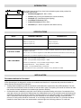
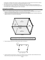
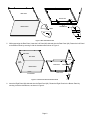
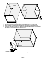
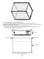
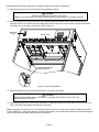
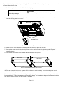
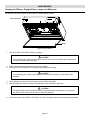
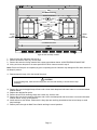
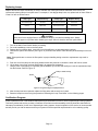
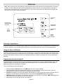
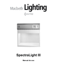
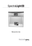
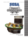
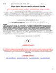
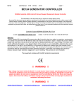
SpectraLight III
Operation Manual
CE DECLARATION
Manufacturer's Name:
X-Rite, Incorporated
Authorized Representative: X-Rite, Incorporated
Siemensstraße 12b • 63263 Neu-Isenburg • Germany
Phone: +49 (0) 61 02-79 57-0 • Fax: +49 (0) 61 02 -79 57-57
Model Name/No.:
SpectraLight III
Directive(s) Conformance:
EMC 89/336/EEC
LVD 73/23/EEC
NOTE: This is a Class A product. In a domestic environment this product may cause radio interference in
which case the user may be required to take adequate measures.
WARRANTY INFORMATION
X-Rite products meet the Restriction of Hazardous Substances (RoHS) Directive 2002/95/EC and
European Union – Waste Electrical and Electronic Equipment (WEEE) Directive
2002/96/EC. Please refer to www.xrite.com for more information on X-Rite’s compliance with the
RoHS/WEEE directives.
FEDERAL COMMUNICATIONS COMMISSION NOTICE
NOTE: This equipment has been tested and found to comply with the limits for a Class A digital device,
pursuant to Part 15 of the FCC Rules. These limits are designed to provide reasonable protection against
harmful interference when the equipment is operated in a commercial environment. This equipment
generates, uses, and can radiate radio frequency energy and, if not installed and used in accordance with the
instruction manual, may cause harmful interference to radio communications. Operation of this equipment in a
residential area is likely to cause harmful interference in which case the user will be required to correct the
interference at his own expense.
INDUSTRY CANADA COMPLIANCE STATEMENT
This Class A digital apparatus complies with Canadian ICES-003.
Cet appareil numérique de la classe A est conforme à la norme NMB-003 du Canada.
EQUIPMENT INFORMATION
Use of this equipment in a manner other than that specified by X-Rite, Incorporated may compromise
design integrity and become unsafe.
WARNING: This instrument is not for use in explosive environments.
Page 2
SAFETY INSTRUCTIONS
•
•
•
•
•
•
•
•
PLEASE READ AND FOLLOW INSTRUCTIONS—Read and follow all instructions before you attempt to
assemble, install or operate the unit.
RETAIN THIS MANUAL FOR FUTURE REFERENCE—Once you have read this manual, keep it handy for
others to read or refer to when they need to operate the unit.
OBEY WARNINGS—Please comply with all warnings and safeguards that we provide in this manual. They
have been written to keep you and your unit safe. If the unit is used in a manner not specified in this manual,
the protection provided by the unit may be impaired.
USE ONLY A PROPER POWER SOURCE—Use the proper power source for this unit. Consult the power
label on the back of the unit for this information. Operation with a power source not specified on the power
label may result in inaccurate lighting conditions, damage to the equipment, and possible personal injury.
DO NOT BLOCK VENTS— Light sources contribute heat to the area of operation. SpectraLight III thermal
contribution is 5460 BTU maximum that is dissipated through the vents in the top panel. Blocking of the vent
could result in overheating, mechanical failure, and a fire hazard if flammables or combustibles are present.
PROTECT FROM WATER AND MOISTURE—Do not install overhead luminaires under a sprinkler system.
Maintain electrical safety when you use this unit. Do not use it in an area where there is possible hazard of
electric shock from spilled water or other liquids or uncontrolled moisture.
CLEAN PROPERLY—You can wipe the unit with a clean, white lint-free cloth. Do not apply liquid cleaners or
agents containing wax, since these can yellow and change reflectance and gloss properties. Clean outer
surfaces with a dampened cloth containing a mild soap.
CAREFULLY HANDLE THE LAMPS AND DAYLIGHT FILTERS—Allow the lamps and daylight filters to cool
before handling them. Always use lens paper or an equivalent to handle any of the replacement tungsten
lamps. Skin oils interfere with lamp performance.
WARRANTY INFORMATION
X-Rite, Incorporated (“X-Rite”) warrants each instrument manufactured to be free of defects in material and workmanship
for a period of 12 months, unless different local regulations apply. This warranty shall be fulfilled by the repair or
replacement, at the option of X-Rite, of any part or parts, free of charge including labor, F.O.B. its factory or authorized
service center.
This warranty shall be voided by any repair, alteration, or modification, by persons other than employees of X-Rite, or
those expressly authorized by X-Rite to perform repairs, and by any abuse, misuse, or neglect of the product, or by use
not in accordance with X-Rite's published instructions.
X-Rite reserves the right to make changes in design and /or improvements to its products without any obligation to include
these changes in any products previously manufactured. Correction of defects by repair or replacement shall constitute
fulfillment of all warranty obligations on the part of X-Rite.
THIS WARRANTY IS EXPLICITLY IN LIEU OF ANY OTHER EXPRESSED OR IMPLIED WARRANTIES, INCLUDING
ANY IMPLIED WARRANTY OF MERCHANTABILITY OR FITNESS FOR ANY PARTICULAR PURPOSE. THIS
WARRANTY OBLIGATION IS LIMITED TO REPAIR OR REPLACEMENT OF THE UNIT RETURNED TO X-RITE OR AN
AUTHORIZED SERVICE CENTER FOR THAT PURPOSE.
This agreement shall be interpreted in accordance with the laws of the State of Michigan and jurisdiction and venue shall
lie with the courts of Michigan as selected by X-Rite, Incorporated.
Page 3
INTRODUCTION
The X-Rite SpectraLight III is a visual color evaluation system which provides five
selectable light sources:
• Simulated Daylight (D75, D65, or D50)
•
Horizon (early morning sunrise/afternoon sunset simulation)
•
Illuminant “A” (incandescent home lighting)
•
Cool White Fluorescent (CWF)
•
Custom Fluorescent (TL84 or U30)
•
Ultraviolet (UV- used in conjunction with another source)
SPECIFICATIONS
MODEL
DIMENSIONS
WEIGHT/SHIPPING WEIGHT
ELECTRICAL POWER
OVERHEAD LUMINAIRE
VIEWING BOOTH
Height: 9.5 in (24.1 cm)
Height: 27.5 in (69.9 cm)
Width: 37.1 in (94.2 cm)
Width: 37 in (94 cm)
Depth: 25.7 in (65.3 cm)
Depth: 24.4 in (62 cm)
92 lbs (42 kg)/115 lbs (52 kg)
154 lbs (70 kg)/181 lbs (82 kg), incl. luminaire
Dedicated 20 A line and 20 A line protection configured receptacle, required for 90-120 VAC. Maximum power
dissipation is 1500 watts.
100-117 VAC ± 10% 50/60 Hz supplied with 5-20P NEMA (National Electrical Manufacturers Association) plug
220-240 VAC ± 10% 50/60 Hz supplied with CEE 7/4 a continental Europe plug
Daylight: Two (2) 750 Watt Tungsten Halogen
LAMP COMPLEMENT
Horizon: Four (4) 500 Watt Tungsten Halogen – 2300K
Illuminant A (Incandescent): Two (2) 150 Watt Tungsten Halogen – 2856K
Cool White Fluorescent:
Two (2) F30T8/CW – 4150K
Ultraviolet: Two (2) F30T8 BLB & One (1) F6T5 BLB
Custom Fluorescent: One (1) F30T12/U30 – 3000K or One (1) F30T8/TL84 – 4000K
INSTALLATION
Recommendations for Surround
X-Rite SpectraLight III is designed for critical color evaluation and therefore it is important that precautions betaken to
ensure the best environment for this purpose.
•
Viewing booth installations provide an area which is manufactured in conformance with ASTM standards. The work
surface and surround area of view are neutral in color and low in gloss. The opening of the booth should face an area
that provides the least interference from ambient light (natural or artificial).
•
Overhead luminaire installations require the user to develop a controlled viewing environment. Contamination from
other light sources can minimize the effectiveness of a standardized source, so the evaluation area should always be
shielded from ambient light (natural or artificial). The best location for an overhead luminaire is in a windowless room
with no interference from other light sources. If these conditions are not available, light-tight curtains should be
selected, a viewing booth should be constructed, or an enclosing curtain should be used. The Luminaire should be
installed no closer than 2 feet to the nearest walls to minimize light level uniformity problems. To avoid color
Page 4
misjudgments, the background on which the sample is placed and the surrounding area of view should be neutral in
color and have a low gloss. It is typically recommended that Munsell N7/ is used.
•
White backgrounds are recommended when evaluating low gloss or light color samples, gray backgrounds are
recommended when evaluating medium gloss of intermediate color samples, and matte or flat black backgrounds are
recommended when evaluating high gloss or dark color samples.
Viewing Booth Installation
Note: To ensure adequate support and space for the unit, see “SPECIFICATIONS” on page1.
1. Move the viewing booth shipping container to the general area that the booth is to be used. Be sure to allow for
sufficient room for assembly (approximately 10 ft x 10 ft area is recommended).
2. Carefully unpack and remove the viewing booth components from the shipping containers. Carefully examine each
shipping container for contents before discarding it.
(2)
Rear Panel
(3)
Left
Side Panel
(5)
Front Panel
(4)
Right
Side Panel
(1)
Bottom Panel
FRONT
CAUTION
Avoid scratching the surface of any of the items in the following steps.
3. Place the Bottom Panel (#1) on a clean, smooth surface. See Figure 1.
Slot
Figure 1. Bottom Panel
4. Position the Rear Panel (#2) bottom notches into the Bottom Panel (#1) rear slots. Fasten the Rear Panel to the
Bottom Panel by securing it with two thumbscrews as shown in Figure 2.
Page 5
Rear Panel
Rear of Unit
Bottom Panel
Thumbscrews
Notch
Slot
Figure 2. Rear Into Bottom Panel
5. While supporting the Rear Panel, insert the Left Panel (#3) side tabs into the Rear Panel (#2). Fasten the Left Panel
to the Bottom Panel by securing it with the thumbscrew as shown in Figure 3.
Side Tabs
Rear Panel
Left
Panel
Left
Panel
Rear Panel
Thumbscrews
Bottom Panel
Rear of Unit
Front of Unit
Figure 3. Left Panel Into Rear and Bottom Panel
6. Insert the Right Panel (#4) side tabs into the Rear Panel (#2). Fasten the Right Panel to the Bottom Panel by
securing it with the thumbscrew, as shown in Figure 4.
Page 6
Right Panel
Rear Panel
Side Tabs
Left Panel
Rear Panel
Right Panel
Thumbscrew
Left Panel
Figure 4. Right Panel Into Rear and Bottom Panel
7. Slide the pivot slots on the front panel (#5) onto the pivots located on each of the two side panels.
8. Flex the side panels as necessary so that both ends of the front panel rest on their respective pivots.
9. Pivot the front panel upwards toward the unit and secure it in place by rotating it about the pivots and locking in
place with the left and right side panel spring clips. See Figure 5.
Front Panel
Side Panel Spring Clips
Front Panel Notches
Front Panel
Pivot
Figure 5. Front Panel Assembly
Page 7
Figure 6. SpectraLight III Viewing Booth
10. The Spectralight Booth is now fully assembled. See Figure 6.
11. Place the viewing booth on the table or bench capable of holding a minimum of 300 lbs (136 kg).
Note: The table or bench height should be determined by the average height of the observer and whether observations
will be made from a standing or sitting position.
12. Carefully unpack and remove the overhead luminaire from its shipping container.
13. With its controls and indicators facing to the front, carefully place the luminaire atop the viewing booth. Align the
luminaire with the positioning tabs on the viewing booth.
Luminaire
Positioning Tab
Positioning Tab
Assembled Booth
Figure 7. Luminaire Placement
Page 8
The SpectraLight III diffuser is shipped in a separate container and must be installed next.
14. Carefully unpack and remove the diffuser from its shipping container.
CAUTION
Be careful not to scratch the interior of the booth.
Make sure the hinge pins are carefully placed behind the Horizon lamps to avoid lamp breakage.
15. Insert the diffuser hinge pins into the front of the slotted receptacles located at the bottom rear corners of the
luminaire housing. The smooth side of the diffuser should face the interior of the luminaire, and the textured side
should face out, to the interior of the booth. Refer to Figure 8.
Main Power
Switch
Diffuser Latch
Horizon Lamp
Notched Receptacles for
Diffuser Hinge Pins
Figure 8. Luminaire Showing Diffuser
16. Rotate the diffuser to its closed position and secure it in place with the latch.
CAUTION
Ensure that the diffuser latch is secured before releasing. Failure to do so may result in the
diffuser sliding out of position.
17. Plug SpectraLight III into a power source matching the voltage specified on the power label on the rear of the unit.
Turn on the Main Power Switch located on the front panel.
Note: Immediately upon power up, the unit will go through a brief system test to ensure that the voltage and electrical
line are satisfactory. Testing Line appears in the front panel display. The incandescent lamps will be powered during the
test. Once the test is complete, the unit is ready for operation
Page 9
Overhead Luminaire Installation
The following describes single- and dual-overhead luminaire installation.
CAUTION
Do not install the overhead luminaire under a fire sprinkler system. Dissipated heat from the
luminaire may cause the sprinkler system to activate.
1. Carefully unpack and remove the SpectraLight III from its shipping container.
2. Remove the eyebolts (four for the single overhead, eight for the dual overhead) from the accessory package and
screw them into the weld nuts located on top of the unit. Refer to Figure 9.
Eyebolts
Figure 9. Overhead Luminaire
CAUTION
In the following step, ensure adequate support. Each unit weighs 92 lbs. (41.7 kg).
3. Attach chains (not supplied) to each of the eyebolts and suspend the unit(s) at the appropriate height and angle
over the work area. The luminaire should be installed so that it is a minimum of two feet from any wall. Refer to
Figure 10.
8 1/2"
36"
30° ± 3°
30° ± 3°
31" ± 2"
Table
6'0" ± 2"
Table
Figure 10. Recommended Overhead Luminaire Installation
Page 10
36"
SpectraLight III is shipped with its lamps and daylight filters installed. The diffuser is shipped in a separate container and
must be installed at this point.
4. Carefully unpack and remove the diffuser from its shipping container.
CAUTION
In the following step, make sure the hinge pins are carefully placed behind the Horizon lamps to
avoid lamp breakage.
5. Insert the diffuser hinge pins into the front of the slotted receptacles located at the bottom rear corners of the
luminaire housing. Refer to Figure 11.
Diffuser Latch
Horizon Lamps
Notched Receptacles for
Diffuser Hinge Pins
Figure 11. Luminaire Showing Diffuser Mounting
6. Rotate the front of the diffuser to its closed position and secure it in place with the latch.
7. Connect the remote control (optional with the single unit) to the front panel at the location marked “Remote.”
8. For single-overhead installations, go to step 10. For dual overhead installations, repeat steps 4 through 6 for the
second luminaire.
9. Connect the dual luminaire cable between the two luminaires. See Figure 12.
Cable
Rear of Unit
Rear of Unit
Figure 12. Dual Overhead Luminaire Cable Conection
10. Plug each luminaire into its own, separate 20 A circuit (one for each luminaire). Turn on the main power switch
located on the front panel.
Note: Immediately upon power up, the unit will go through a brief system test to ensure that the voltage and electrical
line are satisfactory. Testing Line appears in the front panel display. The incandescent lamps will be powered during the
test. Once the test is complete, the unit is ready for operation.
Page 11
MAINTENANCE
Cleaning the Diffuser, Daylight Filters, Lamps, and Reflectors
To clean the unit; refer to Figure 13 and Figure 14, and proceed as follows:
Main Power Switch
Diffuser
Figure 13. Open Luminaire
1. Turn off the Main Power Switch before proceeding.
CAUTION
In the following step, make sure there are no objects in the way of the diffuser upon release and
be careful to gently lower the diffuser.
2. Release the diffuser latch located at the front of the diffuser.
3. Lower the front of the diffuser to its completely opened position (vertical).
CAUTION
In the following step, make sure the hinge pins are removed carefully to avoid Horizon lamp
breakage.
4. Lift the diffuser up to remove the hinge pins from the slotted receptacles.
5. Wash the glass with water containing a mild detergent; rinse thoroughly, and air dry.
CAUTION
The daylight filters and incandescent lamps get very hot during normal operation. Do not touch
the filters or lamps; allow time for them to cool before cleaning.
6. Unscrew the quarter-turn fastener. See Figure 14 on the next page. Gently rotate the filter pack downward.
Page 12
BLB
Cool White Fluorescent
Hinge
Custom Fluorescent
Horizon
Hinge
Filter Pack
UV
Illuminant "A"
Horizon
Quarter
Turn
Fastener
Vent
Quarter
Turn
Fastener
Custom Fluorescent
Cool White Fluorescent
BLB
Figure 14. Filter and Lamp Location
7.
8.
9.
10.
Slide the filter pack sideways and remove it.
Remove dust with a clean, dry, lint-free cloth.
Remove dirt and other foreign material with a spray-type window cleaner. AVOID EXCESSIVE MOISTURE.
Air dry and return the pack to the same position from which it was removed in step 6.
Note: Ensure the filter pack is completely dry prior to operating the unit. Moisture may damage the filter when heat from
the lamps is present.
11. Repeat steps 6 through 10 for the second filter pack.
CAUTION
In the following step, make sure the hinge pins are removed carefully to avoid Horizon lamp
breakage.
12. Remove dirt from the daylight lamp reflectors with a clean cloth dampened with warm water or an ammonia-based
window cleaner.
13. Replace the daylight filter packs.
14. Remove dust from all remaining lamps with a clean, dry, lint-free cloth.
15. Remove dirt from all the remaining reflectors with a clean cloth dampened with warm water or an ammonia-based
window cleaner. Air dry all components.
16. Install and secure the diffuser. Make sure the hinge pins are carefully placed behind the horizon lamps to avoid
lamp breakage.
17. Restore power through the Main Power Switch and begin normal operation.
Page 13
Replacing Lamps
Replace burned out lamps immediately in order to maintain the overall performance standards of the fixture. We
recommend replacing lamps in complete sets. For example, if one daylight lamp burns out, replace both of them. Refer to
“Parts List” later in this document.
Lamp Type
Replace Every
Lamp Type
Replace Every
Simulated Daylight
400 hours
Cool White Fluorescent
4000 hours
Horizon
2000 hours
Ultraviolet 30 Watt
4000 hours
Illuminant “A”
2000 hours
Ultraviolet 6 Watt
4000 hours
CAUTION
Allow time for the daylight filters or incandescent lamps to cool before handling them. Always
use lens paper or equivalent when handling the lamps. Skin oils interfere with their performance.
1.
2.
3.
4.
Turn off the Main Power Switch before proceeding.
For booth installations, remove the front panel.
Release the front diffuser latch. Lower the front of the diffuser to its opened position (vertical).
Unscrew the quarter-turn fastener (see Figure 14.) and lower the diffuser. Slide the filter packs sideways to remove
them.
Note: Take special care to remove the filter packs. Improper handling during removal or replacement may result in
breakage.
5. Push one end of the lamp into the spring loaded socket with pressure to release the other end from its socket.
6. Lift the lamp clear of both sockets and discard in an appropriate receptacle.
7. Using a piece of lens paper (or equivalent) placed between your thumb and forefinger; insert the replacement lamp
into the sockets. Refer to Figure 15.
Grasp in middle of lamp
Socket
Figure 15. Tungsten-Halogen Lamp Replacement
8. After the lamp has been replaced, replace the filter packs and secure them in place.
9. Reset the lamp time meter using the procedure “Resetting the Lamp Time Meter” on the following pages.
Certification Program
X-Rite is pleased to offer a Preventative Maintenance and Certification service for users of SpectraLight viewing systems.
This factory authorized service provides a Certificate of Performance with traceability to A2LA (American Association for
Laboratory Accreditation) for the line of SpectraLight viewing systems. Annual completion of this service is recommended
and will provide you with the assurance that your system meets the specified requirements for color rendering quality.
Page 14
OPERATION
Note: When powering off the SpectraLight III using the Main Power Switch, wait at least 5 seconds before you power it
on again. This will enable all of the firmware and hardware to properly shut off. If you attempt power on less than 5
seconds after the power off, the unit may not power up. If this occurs, power off the unit, wait at least 5 seconds, and
then power it on using the Main Power Switch.
Source Off
Button
Display shows
light source and
hour meter
Program Set/
Save Button
Program Run
Button
Lamp
Source
Buttons
Remote
Control
Receptacle
Selecting a Light Source
To select a light source for viewing a sample, simply press and release the button on the front panel for the light source.
The source remains on until you select another light source or press the Source Off button on the membrane panel.
Using the Source Off Button
The Source Off Button should be used to turn off a selected lamp. You can think of using this button as putting the unit in
“idle” until another lamp source is selected. Do not use the Source Off Button to power off the entire unit. You should use
the Main Power Switch (located to the left of the Membrane Panel) to completely cut power to the unit for maintenance
purposes.
Programming the SpectraLight III
The SpectraLight III can be programmed to power a sequence of light sources, each for a specified period of time. The
program is helpful if you want to view a sample under several light sources in succession and focus on the sample’s
appearance rather than operating the front panel.
To set up the program, proceed as follows:
1. Press and hold the Set/Save button until PGM: appears in the front panel display.
2. Press and hold the light source button for the first source in the sequence. Hold the button for the number of
seconds the source should be powered in the sequence and then release.
3. Seconds= ## appears in the front panel display. ## indicates the number of seconds the button has been held. For
example, press and hold the Cool White button for three seconds. Seconds=03 appears in the display.
4. PGM: XX appears in the display. XX indicates the light source you selected. For example, PGM: CW indicates that
Cool White Fluorescent is the first source in the sequence.
5. Repeat step 2 for the next light source in the sequence.
Page 15
6. PGM: XX YY appears in the display. YY indicates the second light source in the sequence. For example,
PGM:CW HR indicates that Cool White Fluorescent is the first source and Horizon is the second source in the
sequence.
7. Repeat step 2 for the remaining light sources in the sequence.
8. Press the Set/Save Button to save the program. Program Saved appears in the display. You are now finished with
programming the SpectraLight III.
9. To change the program at any time, repeat the above sequence of steps and any previous program is erased.
Running the Program
To run the program on a single unit, proceed as follows:
1. Press the Run button. The unit indicates “L/AUTO” in the display.
2. The SpectraLight III runs the program. The sources are powered in the sequence you programmed. The program
continually runs until you press the Source Off button.
To run the program in a Master/Slave Setup (daisy chain configuration), proceed as follows:
1. Press the Run button twice on the master unit. The unit indicates “R/AUTO” in the display.
2. The SpectraLight III runs the program. The sources are powered in the sequence you programmed on the master
and slave units. The program continually runs until you press the Source Off button on the master unit.
Note: You should not press the UV source button while the program is running. If this occurs, the program will stop
regardless if it is finished. You must press another source button to reset the unit and then run the program again. If you
need UV in the program, you must re-program the unit. Follow the instructions described in "Programming the
SpectraLight III".
Using the Automatic Shut-Off Feature
The SpectraLight III Daylight lamps have the shortest life among all the lamps in the unit. To reduce the frequency of
Daylight lamp replacement, the SpectraLight III has a feature called “Automatic Shut-Off.” This feature automatically
switches the lamp source from Daylight to Cool White Fluorescent after a period of five minutes. This feature is helpful if a
user leaves the booth with the Daylight source selected and does not switch to another source. The Automatic Shut-Off
feature is automatically enabled and is indicated by an * in the display.
You can temporarily disable the Automatic Shut-Off feature. To do so, proceed as follows:
1. While the Daylight source is selected, press the Daylight button.
2. AUTO SHUTOFF DE-ACTIVATED appears in the display. Notice that the * no longer appears in the display.
3. If the Daylight lamp is powered for more than five minutes, it remains selected until you select another source.
The Automatic Shut-Off Feature is enabled again by turning the Daylight source off and then on again. To do this,
proceed as follows:
1. While the Daylight source is selected, press the Source Off button. The Daylight source is turned off.
2. Press the Daylight source button. DAYLIGHT * appears in the display. The Auto Shut-Off is enabled.
Resetting the Lamp Time Meter
The SpectraLight III allows the user to replace lamps. After lamp replacement, you should reset the time meter for the new
lamp. To reset the lamp time meter, proceed as follows:
1.
2.
3.
4.
Press and hold the source button for the replaced lamp for five seconds.
PRESS SET/SAVE TO CONFIRM RESET appears in the display.
Press the Set/Save button.
The hours are set to zero (0).
Page 16
Interpreting Diagnostic Messages
The SpectraLight III may display one of these diagnostic messages in the event that a situation has occurred which
prevents the SpectraLight III from operating normally. The messages and troubleshooting suggestions are listed below.
I got this message...
What does it mean?
What should I do?
Over temperature
The unit is overheating.
1) Turn off the unit using the Main Power Switch.
2) Make sure there is nothing on top of the unit blocking
airflow. If so, remove the object and turn on the unit.
3) If no objects are found or the message remains after
you turn on the unit, proceed to step 4.
4) Call X-Rite for assistance.
Line Problem
Daylight Lamp
Burned Out
There is an electrical
power problem.
1) Turn off the unit and then turn on the unit.
The Daylight Lamp
needs to be replaced.
1) Turn off the unit using the Main Power Switch.
2) If the message remains, call X-Rite for assistance.
2) Follow the procedure “Replacing Lamps” on the
previous pages.
Page 17
Parts:
Consult your X-Rite Price List for additional Lamp Kit Options or call your local X-Rite office.
SPL (Daylight) Lamp Kit
A-L/SPLD
SPL III (TL84) Complete Lamp Kit
A-LK/SPL84
This kit consists of two (2) 750 Watt Tungsten Halogen lamps. Two
(2 )required for the SPL III. Sold in packages of two (2) or as part of a
specific lamp kit.
This kit consists of two (2) 750 Watt Tungsten Halogen Daylight
lamps, four (4) 500 Watt Tungsten Halogen Horizon lamps, two (2)
150 Watt Incandescent lamps, two (2) F30T8/TL84 Fluorescent lamps,
two (2) F30T8/BLB UV lamps, and one (1) F6T5/BLB UV lamp. The
quantities provided in kit represent the number of each lamp required
for each SpectraLight III. Lamps are sold in packages of fifteen (15) or
as part of a specific lamp kit.
SPL (Horizon) Lamp Kit
A-L/SPLH
This kit consists of four (4) 500 Watt Tungsten Halogen lamps. Four
(4) required for the SPL III. Sold in packages of four (4) or as part of a
specific lamp kit.
SPL (Illuminant “A”) Lamp Kit
A-L/SPLIA
This kit consists of two (2) 150 Watt Incandescent lamps. Two
(2)required for the SPL III. Sold in packages of two (2) or as part of a
specific lamp kit.
SPL (CWF) 36" Lamp Kit
A-L/SPLCW
This kit consists of two (2) F30T8/CW Cool White Fluorescent lamps.
Two (2) required for the SPL III. Sold in packages of two (2) or as part
of a specific lamp kit.
SPL (TL84) 36" Lamp Kit
A-L/SPL84
This kit consists of two (2), F30T8/TL84 Fluorescent lamps. Two (2)
lamps required for the SPL III. Sold in packages of two (2) or as part
of a specific lamp kit.
SPL (U30) 36" Lamp Kit
A-L/SPLU30
This kit consists of two (2), F30T8/U30 Ultralume 30 Fluorescent
lamps. Two (2) required for the SPL III. Sold in packages of two (2) or
as part of a specific lamp kit.
SPL (Ultraviolet 30 Watt) 36" Lamp Kit
A-L/SPLUV
This kit consists of two (2) F30T8/BLB Ultraviolet lamps. Two (2)
required for the SPL III. Sold in packages of two (2) or as part of a
specific lamp kit.
SPL (Ultraviolet 6 Watt) Lamp Kit
A-L/SPLUV6W
This kit consists of two (2) F6T5/BLB Ultraviolet lamps. One (1)
required for the SPL III. Sold in packages of two (2) or as part of a
specific lamp kit.
SPL III (U30) Complete Lamp Kit
A-LK/SPLU30
This kit consists of two (2) 750 Watt Tungsten Halogen Daylight
lamps, four (4) 500 Watt Tungsten Halogen Horizon lamps, two (2)
150 Watt Incandescent lamps, two (2) F30T8/U30 Fluorescent lamps,
two (2) F30T8/BLB UV lamps, and one (1) F6T5/BLB UV lamp. The
quantities provided in kit represent the number of each lamp required
for each SpectraLight III. Lamps are sold in packages of fifteen (15) or
as part of a specific lamp kit.
SPL III Daylight Filter Pack (D75) VB or OVHD
A-FP/SPL75
Patented D75 North Sky Daylight at 7500 K filter pack assembly. For
SPL III Viewing Booths only. Two (2) required for the SPLIII. Sold in
packages of two (2).
SPL III Daylight Filter Pack (D65) VB or OVHD
A-FP/SPL65
Patented D65 Average North Sky Daylight at 6500 K filter pack
assembly. For SPL III Viewing Booths only. Two (2) required for the
SPL III. Sold in packages of two (2).
SPL III Daylight Filter Pack (D50) VB or OVHD
A-FP/SPL50
Patented D50 Noon Sky Daylight at 5000 K filter pack assembly. For
SPL III Viewing Booth or Overhead Luminaire. Two (2) required for the
SPL III. Sold in packages of two (2).
SPL Diffuser and Door Assembly
A-AK/SPLDD
Prismatic “water white” glass diffuser. For SPL III Viewing Booth or
Overhead Luminaire. One (1) required for the SPL III. Sold in
packages of one (1).
SPL Remote Control Kit
A-CK/SPLR
Tethered remote control for use with the SPL III Viewing Booth or
Overhead Luminaire.
X-Rite makes no warranty of any kind with regard to the material contained in this manual, including implied warranties or fitness for a particular purpose.
X-Rite shall not be liable for errors contained herein or for incidental or consequential damages in connection with the performance or use of this
material. This manual is the copyright of X-Rite. Any reproduction of the publication in whole or in part without the express permission of X-Rite is a
breach of this copyright. SpectraLight® is a registered trademark of X-Rite, Incorporated.
Page 18
Corporate Headquarters - USA
4300 44th Street SE
Grand Rapids, Michigan 49512
Phone 1 800 248 9748 or 1 616 803 2100
Fax 1 800 292 4437 or 1 616 803 2705
Corporate Headquarters - Europe
Althardstrasse 70
8105 Regensdorf
Switzerland
Phone (+41) 44 842 24 00
Fax (+41) 44 842 22 22
Corporate Headquarters - Asia
Room 808-810
Kornhill Metro Tower, 1 Kornhill Road
Quarry Bay, Hong Kong
Phone (+852) 2 568 6283
Fax (+852) 2 885 8610
Please visit www.xrite.com for a local office near you.
P/N 17500240 Rev. C