1
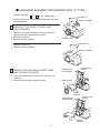
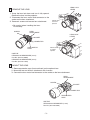
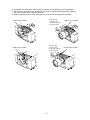
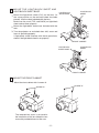
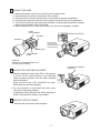
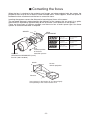
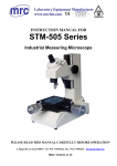
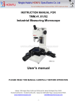
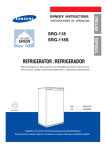
LCD PROJECTOR LENS
MODEL LNS-T33
LENS REPLACEMENT PROCEDURE
NOTE; Lens installation is different in cabinet design (Type A and B). Before installation
the lens, check cabinet design.
Notes on Lens Replacement
● Lens replacement should be performed by the qualified service personnel.
● It should be followed by this procedure precisely.
● Before attempt to replace the lens, confirm the model number (both the
LCD projector and the lens) and use the proper lens.
● The lens cover is on the lens for protection. Be sure to remove the lens
cover before installation.
● When installing or removing the lens, be careful not to stain, scratch or
damage the lens.
● When shipping the projector with the lens, remove the lens before shipping
the projector.
● If you have any questions, contact the dealers.
PARTS LIST
Following parts are contained in the packing.
● LENS
● SCREW DRIVER (3 mm, Green)
● SCREW DRIVER (4 mm, Yellow)
● LIGHT-BLOCK SHEET
● SPACER
● CABLE TIE
1 piece
1 piece (Part No. 910 287 7329)
1 piece (Part No. 910 275 6020)
1 piece Type PJ1 (Part No. 610 347 3901)
1set (Part No. 610 301 6658)
2 pieces (Part No. 645 004 5387)
Following checks and confirmations should be taken for safety.
Check the following things by the time of the cabinet mount after the lens replacement.
1. Check the lens is securely fixed.
2. Check the proper wiring and the wires are fixed properly.
3. Check each connector is connected properly.
4. Check no wiring is tangled on the gear of lens motor or the other mechanical parts.
5. Check no parts is missing, or no mounting part is loose.
Some parts are not used for installation or replacement. Keep these parts and
drivers included in the lens for later use.
Printed in Japan
1AA6P1P5722-- (IFRD)
■ LENS REPLACEMENT PROCEDURE (FOR "A" TYPE )
Perform the steps 1 to
6 for lens replacement.
SCREW "A"
At first set the lens at the fully lower position with lens
shift adjustment.
1
FRONT CABINET
R E M OV E T H E L E N S C OV E R A N D
FRONT CABINET
1. Turn the lens cover to counter-clockwise and pull it
toward front and remove the lens cover.
2. Remove 2 screws-A.
3. Remove the front cabinet
LENS COVER
SCREW "A"
1. Remove 2 screws-A.
2. Remove the front cabinet
FRONT CABINET
2
REMOVE THE LIGHT-BLOCK SHEET BASE
AND LIGHT-BLOCK SHEET
LIGHT-BLOCK
SHEET
LIGHT-BLOCK
SHEET BASE
1. Slide the light-block sheet base upward and
remove it.
2. Remove the light-block sheet from lens.
LENS COVER
FRONT
CABINET
LIGHT-BLOCK
SHEET BASE
LIGHT-BLOCK
SHEET
FRONT
CABINET
--
3
LENS LOCK
LEVER
REMOVE THE LENS
1. Grasp the lens lock lever and turn it fully upward.
Remove the lens into the projector.
2. Disconnect the lens motor lead connector to the
socket on the lens attachment.
3. Remove 4 screws and remove lens attachment.
Pull the lens
lock lever
upward
※ Be careful when handling the lens.
Do not drop.
LENS
ATTACHMENT
SCREW
LENS LOCK
LEVER
SOCKET
CONNECTOR
LENS MOTOR
LEAD
Pull the lens
lock lever
upward
USE THE
HEXAGON SCREWDRIVER (4 mm)
Part No. (910 275 6020)
HEXAGON SCREWDRIVER (3 mm)
Part No. (910 287 7329)
4
MOUNT THE LENS
1. Remove protective caps (front and back) on the optional lens.
2. Mount the lens on the lens attachment with 4 screws.
3. Connect the lens motor lead connector to the socket on the lens attachment.
LENS
ATTACHMENT
SCREW
SOCKET
CONNECTOR
LENS MOTOR
LEAD
USE THE
HEXAGON SCREWDRIVER (4 mm)
Part No. (910 275 6020)
--
4. Grasp the lens lock lever and turn it fully upward. Install the lens into the projector.
5. Turn the lens lock lever fully downward until lever is locked (clicked position) properly.
Be sure to mount lens motor on left-side.
6. After installing the lens, make sure the lens is not loose and properly installed.
Push the lens
lock lever fully
downward until it is
locked (clicked).
LENS LOCK LEVER
Push the lens
lock lever fully
downward until it is
locked (clicked).
LENS LOCK LEVER
--
LENS LOCK LEVER
LENS LOCK LEVER
5
MOUNT THE LIGHT-BLOCK SHEET AND
LIGHT-BLOCK SHEET BASE
1. Mount the light-block sheet (PJ1) on the lens. (In
LIGHT-BLOCK
SHEET BASE
LIGHT-BLOCK
SHEET
the same position as the removed sheet has been
placed). Use the sheet included with the lens.
Make sure the mark (TOP and BACK) on light-block
sheet and set them properly.
2. Mount the light-block sheet base included with the
lens.
3. Turn the projector on and check lens shift, zoom and
focus is operating properly.
If light-block sheet interfere with those operations,
check if the light-block sheet is set properly.
FRONT CABINET
LIGHT-BLOCK
SHEET BASE
LIGHT-BLOCK
SHEET
FRONT CABINET
6
MOUNT THE FRONT CABINET
1. Mount the front cabinet with 2 screws-A.
SCREW "A"
SCREW "A"
The removed lens cover is not uesd for
the installation of this lens. Keep this lens
cover with provided drivers for later use.
--
■ LENS REPLACEMENT PROCEDURE (FOR "B" TYPE )
Perform the steps 1 to
6 for lens replacement.
Shift the lens to the center position by using the lens
shift function.
1
TOP COVER
RELEASE BUTTON
REMOVE THE TOP COVER
1. While pressing the top cover release button on
the top cover, slide the top cover toward front to
remove it.
TOP COVER
2
REMOVE THE LIGHT-BLOCK SHEET
LIGHT-BLOCK
SHEET
1. Slide the light-block sheet upward and remove it.
3
REMOVE THE LENS
1. Hold the lens with one hand and pull the lens lock
lever upward with the other hand. Remove the lens
from the projector.
2. Disconnect the lens motor lead connector from the
socket on the lens attachment.
3. Remove 4 screws and remove lens attachment.
SCREW
LENS
ATTACHMENT
LENS LOCK
LEVER
Pull the lens
lock lever
upward
SOCKET
CONNECTOR
LENS MOTOR
LEAD
USE THE
HEXAGON SCREWDRIVER (4 mm)
Part No. (910 275 6020)
※ Be careful when handling the lens.
Do not drop.
--
4
MOUNT THE LENS
1.
2.
3.
4.
5.
Remove protective caps (front and back) on the optional lens.
Mount the lens on the lens attachment with 4 screws.
Connect the lens motor lead connector to the socket on the lens attachment.
Grasp the lens lock lever and turn it fully upward. Install the lens into the projector.
Turn the lens lock lever fully downward until lever is locked (clicked position) properly.
Be sure to mount lens motor on left-side.
6. After installing the lens, make sure the lens is not loose and properly installed.
LENS
ATTACHMENT
LENS LOCK LEVER
SOCKET
SCREW
Push the lens
lock lever fully
downward until it is
locked (clicked).
CONNECTOR
LENS MOTOR
LEAD
USE THE
HEXAGON SCREWDRIVER (4 mm)
Part No. (910 275 6020)
5
LIGHT-BLOCK SHEET
TYPE PG1
MOUNT THE LIGHT-BLOCK SHEET
1. Slide the light-block sheet (Type PG1) in the groove
to mount. (In the same position as the removed
sheet has been placed). Use the sheet included
with the projector.
Make sure the mark (TOP and BACK) on lightblock sheet and set them properly.
2. Turn the projector on and check lens shift, zoom
and focus is operating properly.
If light-block sheet interfere with those operations,
check if the light-block sheet is set properly.
6
MOUNT THE TOP COVER
1. Slide the top cover back to the projector.
--
■ Correcting
the focus
When the lens is attached to the projector and images are being projected onto the screen, the
peripheral focus may be out of focus in some localized areas. If this happens, insert the spacer in
between the lens attachment and the lens to correct the focus.
Inserting the spacers corrects the distance for best diagonal focus at the screen.
The corrected distance is determined by the thickness of the spacers that are used. As a guide,
the distance is adjusted by approximately 30 mm for each 0.1-mm thickness of the spacers.
There are three types of spacers provided, and there are four of each spacer type. Use these
spacers to correct the distance as required.
SPACER
A
B
LENS
ATTACHMENT
C
D
A~D
Insertion position
of the focus
correction spacers.
Spacer "1"
Color; Clear
Thickness; 0.1 mm
Correction distance
30 mm/for 40-inch
projection
Spacer "2"
Color; Black
Thickness; 0.2 mm
Correction distance
55 mm/for 40-inch
projection
Spacer "3"
Color; Cream
Thickness; 0.3 mm
Correction distance
80 mm/for 40-inch
projection
USE THE
HEXAGON SCREWDRIVER (4 mm)
Part No. (910 275 6020)
Screen
A”
Screen
40-inch projection
D”
B”
C”
Distance
Insert spacers in the location A"~D" (above figure)
corresponding to the screen location A~D.
--