1
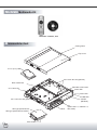
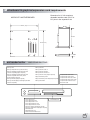
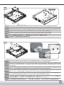
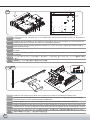
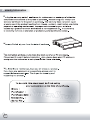
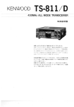
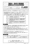
Product overview ML02ʟML02MX Specification Material Acrylic front panel, 4.0mm aluminum frames, SECC body Color Black plus silver SST-ML02B-R (black,w/out LCD panel) Model SST-ML02B-MXR (black,with LCD panel) Motherboard Micro ATX, Mini-ITX, DTX External Slim optical slot x 1 Drive Bay internal 3.5” x 1 or 2.5” x 1 (vibration dampening) Cooling System Expansion Slot Top Oversized venting holes Sides 50mm fan slot x 3 Rear 50mm fan x 1 1 (includes 1 X PCI & 1X PCI-E riser cards) USB2.0 x 2;IEEE1394 x 1;audio x 1;MIC x 1; Front I/O Ports 52-in-1 card reader Power Supply Fanless 120W DC/DC board & AC adapter Net Weight 4 kg Dimension 397mm (W) x 82mm (H) x 375mm (D) 02 ML02MX Multimedia Kit Remote control, CD Disassemble chart Venting holes Top cover 3.5" or (2.5") HDD 50 x 15mm fan slot (optional) Riser card brace 120W DC to DC board Power SW 50 x 15mm fan Power LED HDD LED LCD/IR (ML02MX) 50 x 15mm fan slot (optional) Silm type optical device Silm type optical device bracket Card reader 03 Door I/O (IEEE 1394 x 1, USB 2.0 x 2, MIC, SPK) Motherboard & graphics/expansion card requirements Dimension for LC19's maximum allowable interface card (PCI-E or PCI) size in the expansion slot MICRO ATX MOTHERBOARD 244mm ( 9.6'') 98.4mm M L 171.8mm J H 2 1 F C Card reader/writer S R 3 4 244 mm ( 9.6'' ) B 19mm MMC/SD/MS/SM/CF/MD Memory Stick Memory Stick Pro Memory Stick(with memory select function) Memory Stick Pro Ultra II Memory Stick(Magic Gate/High Speed data transfer compatible)(adaptor required) Memory Stick Pro Extreme Memory Stick(Magic Gate/High Speed data transfer compatible with memory select function)(adaptor required) Memory Stick Pro Duo (adaptor required) Memory Stick Pro Extreme III Magic Gate Memory Stick Magic Gate Memory Stick Duo(adaptor required) Memory Stick Duo(adaptor required) Memory Stick Duo(Magic Gate/High Speed data transfer compatible) Memory Stick ROM Secure Digital Card Secure Digital PRO Card Secure Digital Ultra II Card Secure Digital Extttreme Card Secure Digital Extttreme III Card Mini Secure Digital Card(adaptor required) Mini Secure Digital PRO Card(adaptor required) Multi Media Card Multi Media PRO Card Reduced Sized Multi Media Card Compact Flash Card TYPE I Compact Flash Card TYPE II Compact Flash Ultra Card TYPE I Compact Flash Ultra I Card TYPE I Compact Flash Extreme III Card Micro Drive Card Smart Media Card 04 This is a unique product,please read the following detailed installation guide we have prepared meticulously for you. ıIJ ENGLISH Loosen three screws from the rear of the chassis Bitte lösen Sie die 3 Schrauben an der Rückseite des DEUTSCH Gehäuses. ESPAÑOL Afloje tres tornillos de la parte trasera de la caja FRANÇAIS Desserrez les 3 vis de l’arrière du boîtier ITALIANO Svitare tre viti dalla parte posteriore del chassis Р ġ ҏ ġ ᇭ ࠪࡖࠪᓟㇱߩࡀࠫ3ᧄࠍᄖߒ߹ߔޕ ϛȁġġġМ ᚬᐠ٘ࡣПέᗻᚇ՞ΰᇐޟᖳ๛ ıij ENGLISH Lift top cover up to remove it from the chassis DEUTSCH Heben Sie den Deckel an, um ihn vom Gehäuse zu entnehmen. ESPAÑOL Levante el panel superior para sacarlo del chasis FRANÇAIS Soulevez le panneau supérieur pour le retirer du boîtier ITALIANO Sollevare il panello superiore per rimuoverlo dal chassis Р ġ ҏ ġ ᇭ ㇱࠞࡃࠍࠤࠬ߆ࠄขࠅᄖߒ߹ߔޕ ϛȁġġġМ өΰܜ։џڥήΰᇐ ıĴ ENGLISH Loosen two screws holding the center brace to remove it DEUTSCH Lösen Sie die 2 Schrauben der mittleren Gehäuseschiene ESPAÑOL Afloje dos tornillos de la abrazadera para sacarla FRANÇAIS Desserrez les 2 vis tenant la barre centrale pour la retirer ITALIANO Svitare 2 viti che fissano il supporto centrale per rimuoverlo Р ġ ҏ ġ ᇭ ࡦ࠲ࡉࠬࠍ⇐ߡࠆࡀࠫ2ᧄࠍᄖߒ߹ߔޕ ϛȁġġġМ ᚬijᗻᖳ๛ϛЛ࢜ڥή 05 ıĵ Screw holes for securing slim optical drive brace ENGLISH Loosen four screws located on the bottom side of the chassis to remove the slim optical drive bracket DEUTSCH Lösen Sie die 4 Schrauben an der Unterseite des Gehäuses um den optischen Slim Käfig herausnehmen zu können. ESPAÑOL Afloje dos tornillos que se encuentran en la parte inferior del chasis para quitar el soporte de la unidad óptica slim FRANÇAIS Desserrez les 4 vis situées dessous le boîtier pour retirer le casier du lecteur optique slim. ITALIANO Svitare 4 viti situate sul fondo del chassis per rimuovere il supporto dell’unità ottica sottile Рġҏġᇭ ࠪࡖࠪᐩㇱߩࡀࠫ4ᧄࠍᄖߒߡဳ⭯ޔశቇ࠼ࠗࡉࡉࠤ࠶࠻ࠍขࠅᄖߒ߹ߔޕ ϛȁġġġМ ᚬᐠ٘ήПĵᗻᖳ๛ᖡӎᆅᐠЛ࢜ڥή ıĶ IJ Ĵ ij Secure motherboard onto the chassis with corresponding screws. If the motherboard has either "S" or "R" ENGLISH type mounting holes, please install the included screw holder from the accessories bag Befestigen Sie das Motherboard auf den zugehörigen Halterungen mit Schrauben. Sollten Sie ein Motherboard DEUTSCH mit "S" oder "R" Bauart benutzen, so installieren Sie bitte die zusätzlichen Motherboard Abstandshalter aus dem Zubehörpaket. ESPAÑOL Sujete la placa base sobre el chasis con los tornillos correspondientes. Si la placa base tiene agujeros de tipo “S” o “R”, inserte también el portatornillos que se encuentra en la caja de los accesorios FRANÇAIS Fixez la carte mère dans le boîtier avec les vis adéquates. Si la carte mère possède des trous de montage de type “S” ou “R”, veuillez installer les supports de vis inclus dans le sachet d’accessoires. ITALIANO Fissare la scheda madre sul chassis con le viti correspondenti. Se la scheda madre ha dei fori di montaggio di tipo “S” o “R” utilizzare gli appositi tasselli per le viti, che si trovano nella scatola degli accessori. Рġҏġᇭ ࡑࠩࡏ࠼ࠍࠪࡖࠪߦኻᔕߒߚࡀࠫߢ࿕ቯߒ߹ߔ̌ ߦ࠼ࡏࠩࡑޕS̍߹ߚߪ̌R̍࠲ࠗࡊߩขࠅઃ ߌⓣ߇ࠆ႐วߪࠢ࠶ࡄࠨࠢࠕޔౝߩࡀࠫࡎ࡞࠳ࠍขࠅઃߌߡߊߛߐޕ ϛȁġġġМ кᐠݖᚇܻھᐠ٘ۻ৴ࣺᄇᔖޟЌΰȂषԤкᐠݖΰԤŔܖœЌȂѪѴԊ၆ႭӇѓϛޟᖳ๛৴Սۻ৴Ȅ 06 ıķ B B A : 2.5" B : 3.5" A A A A B B ENGLISH Install hard drive (can use either 2.5" or 3.5" size) into the case and secure it with screws from the bottom of the chassis DEUTSCH Installieren Sie die Festplatte in das Gehäuse und befestigen Sie sie mit Schrauben von der Unterseite des Gehäuses(Sie können entweder 2,5" oder 3,5" Festplatten installieren). ESPAÑOL Instale el disco duro(se pueden utilizar las medidas 2.5” o 3.5”) en la caja y sujetelo atornillando desde la parte inferior de la caja. FRANÇAIS Installez le disque dur (vous pouvez utiliser un disque 2.5” ou 3.5”) dans le boîtier et fixez-le par le dessous du boîtier. ITALIANO Installare l’hard disk( è possible usare la misura 2.5” o 3.5”) nel case e fissarlo con le viti, avvitando dal fondo del chassis. Рġҏġᇭ ࡂ࠼࠺ࠖࠬࠢ࠼ࠗࡉ㧔ࠨࠗ࠭ߪ2.5̍߹ߚߪ3.5̍ߕࠇ߽น㧕ࠍࠤࠬߦࠇࠪࡖࠪޔᐩㇱ߆ࠄ࿕ቯ ߒ߹ߔޕ ϛȁġġġМ ᆅܹΣȂܻήПᚇΰᖳ๛ġџᒵᐅijįĶģܖĴįĶģᆅ ġ PCI ıĸ őńŊ 3 2 PCI PCI PCI PCI IPC PCI-Express 4 1 Exp s res PCI I PC 07 ENGLISH Install PCI riser card onto the center brace, make sure to install on the side that indicates "PCI" DEUTSCH Installieren Sie die PCI Riserkarte an der Gehäuseschiene aus Schritt 3. Vergewissern Sie sich, dass die Riserkarte an der mit "PCI" markierten Seite installiert wird. ESPAÑOL Instale la tarjeta riser PCI sobre la abrazadera. Tiene que ser montada por el lado que indica”PCI” FRANÇAIS Installez l’adaptateur de carte PCI sur la barre centrale, vérifiez bien de l’installer du côté ou il est indiqué “PCI” ITALIANO Installare la riser card PCI sul supporto centrale. Assicurarsi che sia installato sul lato contrassegnato con”PCI”. Рġҏġᇭ PCIࠗࠩࠞ࠼ࠍࡦ࠲ࡉࠬࠍขࠅઃߌ߹ߔߩߘޕ㓙̌PCI̍ߩ␜߇ࠆߦขࠅઃߌߡߊߛߐޕ ϛȁġġġМ Ԋ၆PCIᙽњܻϛЛ࢜ΰȂݧཎPCIಒဴޟ՝ည ıĸ őńŊĮņŹűųŦŴŴ PCIE őńŊĮņŹűųŦŴŴġřIJķġŪůġŴŭŰŵġIJ 3 PCIE PCI PCI őńŊ 4 2 1 őńŊĮņŹűųŦŴŴġŦŹŵŦůŴŪŰůġŤŢųť ŇŪųŴŵġŴŭŰŵġġ őńŊĮņŹűųŦŴŴ őńŊĮņŹűųŦŴŴġ ŦŹŵŦůŴŪŰůġŤŢųť ŇŪųŴŵġŴŭŰŵ ŇŪųŴŵġŴŭŰŵ ʳ őńŊĮņŹűųŦŴŴġřIJķġŪůġŴŭŰŵġij PCIE ENGLISH 3 PCIE ŔŦŤŰůťġŴŭŰŵ PCI PCI 4 2 1 ŔŦŤŰůťġŴŭŰŵ Use of PCIE riser card can be inserted into the first or the second slot and turn the bracket 180 degrees, and then use 2 screws to secure it on the bracket. Then use 2 screws to secure the bracket on the chassis. DEUTSCH Die PCI-Express Riserkarte kann im ersten oder zweiten Slot benutzt werden und dreht die Halterung um 180°. Benutzen Sie dann zwei Schrauben um die Karte in der Halterung zu fixieren. Benutzen Sie dann zwei Schrauben um die Halterung im Gehäuse zu befestigen. ESPAÑOL La tarjeta riser PCIE puede ser insertada en el primero o segundo slot. Gire la abrazadera de 180 grados y utilize dos tornillos para sujetarla en la abrazadera. Utilize dos tornillos más para sujetar la abrazadera en el chassis FRANÇAIS Les adaptateurs pour PCIE peuvent être insérés dans le premier ou le deuxième emplacement. Tournez le casier à 180 degrés, et ensuite utilisez 2 vis pour les fixer au casier. Puis utilisez 2 vis pour fixer le casier ITALIANO La riser card PCIE può essere inserita nel primo o secondo slot. Girare il supporto di 180 gradi ed utilizzare due viti per fissarla al supporto. Utilizzare altre due viti per fissare il supporto sul chassis. Рġҏġᇭ PCIEࠗࠩࠞ࠼↪ߩ႐วߪ╙1߹ߚߪ╙2ࠬࡠ࠶࠻ߦᝌߒߡࡉࠤ࠶࠻ࠍ180q࿁ォߐߖޔ2ᧄߩࡀࠫ ߢࡉࠤ࠶࠻ߦ࿕ቯߒ߹ߔࠍ࠻࠶ࠤࡉߡߒߘޕ2ᧄߩࡀࠫߢࠪࡖࠪߦ࿕ቯߒ߹ߔޕ ϛȁġġġМ џौٺҢޟőńŊĮņᙽњඨՍΙܖΠඨዀӔװЛ࢜ᙽIJĹı࡙ȂҢڍᗻᖳ๛ѺᚇھӵЛ࢜ΰȄณࡣӔҢ ڍᗻᖳ๛װЛ࢜ᚇھӵᐠ෦Ȅ 08 ıĹ ENGLISH Remove expansion slot cover and then re-install the center brace back onto the chassis Entnehmen Sie die Erweiterungskarten-Slotblende und DEUTSCH installieren Sie die Gehäuseschiene wieder in das Gehäuse. ESPAÑOL Quite la tapa del slot de expansión y re-instale la abrazadera sobre el chasis Retirez les équerres PCI et ensuite réinstallez la barre FRANÇAIS centrale dans le boîtier. ITALIANO Rimuovere la mascherina degli slot d’espansione e reinstallare il supporto centrale sul chassis. Рġҏġᇭ ᒛࠬࡠ࠶࠻ߩࠞࡃࠍᄖߒࡉ࠲ࡦߦࠪࡖࠪޔ ࠬࠍᚯߒ߹ߔޕ ϛȁġġġМ ڥήϭ७њඨዀ᐀аȄӔϛЛ࢜ᚇΰijᗻᖳ๛ܻۡھᐠ٘Ȅ ıĺ Insert the PCI riser card's daughter card onto either second, third, or fourth slot (whichever PCI slot is available) ENGLISH on the motherboard. Then install PCI expansion card into the riser card and secure it with screw. Installieren Sie die Daughter-Karte der PCI-Riserkarte in DEUTSCH einen freien PCI Slot Ihres Motherboards. Stecken Sie dann die PCI Erweiterungskarte in die Riserkarte und befestigen Sie diese mit Schrauben. Inserte la tarjeta hija de la tarjeta riser PCI sobre el segundo, tercero o cuarto slot(el que esté disponible) en la ESPAÑOL placa base. Instale la tarjeta de expansión en la tarjeta riser y sujete con los tornillos. Insérez la partie enfant de l’adaptateur pour carte PCI sur le deuxième, troisième ou quatrième emplacement (celui FRANÇAIS qui est disponible) de la carte mère. Puis installez la carte d’extension PCI dans l’adaptateur et fixez-la avec. Inserire la card figlia della PCI riser sul secondo, terzo o ITALIANO quarto slot( a seconda della disponibilità) sulla scheda madre. Quindi installare la card d’espansione PCI nella riser card e fissare con le viti. PCIࠗࠩࠞ࠼ߩ࠼࠲ࡏ࠼ࠍࡑࠩࡏ࠼ߩ2,3,4 Р ġ ҏ ġ ᇭ ⇟⋡ߩࠬࡠ࠶࠻㧔ⓨߡࠆPCIࠬࡠ࠶࠻ߕࠇ߽น㧕ߦ ᝌߒ߹ߔߦ࠼ࠞࠩࠗࠄ߆ࠇߘޕPCIᒛࠞ࠼ࠍࡀ ࠫᱛߒ߹ߔޕ őńŊᙽњ௶৴ԊඨՍкᐠݖΰӈդΙಢőńŊඨዀȄϭ ϛȁġġġМ ७њඨΰőńŊᙽњȂٮиᇄᐠ෦धݖᚇھȄ IJı 09 ENGLISH Install IDE adapter to the back of slim optical drive DEUTSCH Installieren Sie den IDE Adapter an der Rückseite Ihres optischen Slim-Laufwerks. ESPAÑOL Instale el adaptador IDE en la parte trasera de la unidad óptica slim FRANÇAIS Installez l’adaptateur IDE à l’arrière de votre lecteur optique slim ITALIANO Installare l’adattatore IDE sulla parte posteriore dell’unità ottica sottile Рġҏġᇭ IDEࠕ࠳ࡊ࠲ࠍ⭯ဳశቇ࠼ࠗࡉᓟㇱߦขࠅઃߌ߹ߔޕ ϛȁġġġМ ŊŅņᙽݖԊ၆Սᖡӎᆅᐠधݖ IJIJ ENGLISH Install the slim optical drive onto the slim optical drive bracket and secure with screws DEUTSCH Installieren Sie das optische Slim Laufwerk auf den Slim- Laufwerkskäfig und befestigen Sie es mit Schrauben. IJij ESPAÑOL Instale la unidad óptica slim sobre el soporte de la únidad óptica slim y atornille FRANÇAIS Installez le lecteur optique slim dans son casier et vissez-le avec des vis. ITALIANO Installare l’unità ottica sottile nel suo supporto ed avvitare. Рġҏġᇭ ⭯ဳశቇ࠼ࠗࡉࠍ⭯ဳశቇ࠼ࠗࡉࡉࠤ࠶࠻ߦࡀࠫᱛ ߒ߹ߔޕ ϛȁġġġМ ᖡӎᆅᐠᇄᖡӎᆅᐠЛ࢜ᚇھ ENGLISH Insert the slim optical drive with bracket installed into the chassis and secure with screws from the bottom side Fügen Sie den Slim Laufwerkskäfig wieder in das Gehäuse DEUTSCH und befestigen Sie diesen mit Schrauben von der Unterseite des Gehäuses. ESPAÑOL Re-inserte la únidad óptica slim con el soporte instalado, en el chasis y atornille desde la parte inferior. FRANÇAIS Insérez le lecteur optique (installé dans son casier) dans le boîtier et fixez-le avec des vis par le dessous. ITALIANO Inserire nel chassis l’unitá ottica sottile con il suo supporto installato e fissare con le viti, avvitando dal fondo Р ġ ҏ ġ ᇭ ⭯ဳశቇ࠼ࠗࡉࠍขࠅઃߌߚࡉࠤ࠶࠻ࠍࠪࡖࠪߦ ࠇޔᐩㇱ߆ࠄࡀࠫᱛߒ߹ߔޕ ϛȁġġġМ ᖡӎᆅᐠЛܹ࢜ΣȂܻήПᚇΰᖳ๛Ȅ ENGLISH Insert all other components, wires, and cables, then place the top cover back onto the chassis and secure with screws to complete installation IJĴ Schließen Sie alle anderen Komponenten und Kabel an. Zum abschließen der Installation platzieren Sie den Deckel DEUTSCH auf dem Gehäuse und befestigen Sie diesen wieder mit den Schrauben. ESPAÑOL Inserte los demás componentes y cables y recoloque el panel superior sobre el chasis. Atornille la parte superior para completar la instalación FRANÇAIS Insérez tous les autres composants, câbles, puis replacez le panneau supérieur sur le boîtier et fixez-le pour terminer l’installation. ITALIANO Inserie i restanti componenti e cavi, quindi ricollocare il pannello superiore e fissare con le viti per completare l’installazione Рġҏġᇭ ߘߩઁߩᔅⷐߥࠦࡦࡐࡀࡦ࠻࡞ࡉࠤޔ࠼ࠦޔ㘃ࠍ⊝ ߡޔㇱࠞࡃࠍࠪࡖࠪߦᚯߒࠫࡀޔᱛߔࠆߣࠗ ࡦࠬ࠻࡞ߪቢੌߢߔޕ ϛȁġġġМ Ԋ၆ԁܚԤϯӇࡣӔΰᇐ၆ӱᐠ٘Ȃᚇΰӑࠉܶ ήޟĴᗻᖳ๛Ȅ 10 SilverStone ML02MX LCD/IR Insert the 4 pin USB connector from the LCD/IR module to your motherboard ENGLISH USB pin header. You can also use the included USB adapter to connect to an external USB port header on the motherboard. Verbinden Sie den 4 pin USB Anschluss mit den USB-Anschlüssen auf Ihrem DEUTSCH Motherboard. Bitte nutzen Sie zur Installation Ihre Motherboard-Anleitung. Sie können auch den externen USB-Anschluss an der Rückseite Ihres Motherboards nutzen, falls Sie keinen freien Onboard USB-Anschluss haben. Inserte el conector USB de 4 pines del módulo LCD/IR a la cabeza del pin ESPAÑOL USB del motherboard o placa madre. Usted puede utilizar tambien el adaptador incluido USB para conectar un cabezal exterior del puerto USB en el motherboard. Insérez le connecteur 4pin USB du module LCD/ IR aux broches USB de FRANÇAIS votre carte mère. Vous pouvez aussi utiliser 'adaptateur USB inclus pour relier un port USB externe sur la carte mère. Inserire il connettore USB a quattro poli dal modulo LCD/IR allo spinottoUSB ITALIANO della scheda madre. È inoltre possibile utilizzare l’adattatore USB(incluso) per collegare uno spinotto di porto esterno USB sulla scheda madre. LCD/IR ࡕࠫࡘ࡞߆ࠄߩ4ࡇࡦUSBࠦࡀࠢ࠲ࠍߏ↪ߩࡑࠩࡏ࠼ߩ Р ġ ҏ ġ ᇭ USBࡇࡦࡋ࠶࠳ߦᝌߒ߹ߔߪߚ߹ޕઃዻߩUSBࠕ࠳ࡊ࠲ࠍࡑࠩࡏ࠼ߩ ᄖㇱUSBࡐ࠻ࡋ࠶࠳ߦធ⛯ߔࠆߎߣ߽ߢ߈߹ߔޕ ϛȁġġġМ LCD/IRಢޟVTC௶ጣԊ၆ՍкᐠݖȂௌџоٺҢUSBᙽᓞԊ၆Սк ᐠݖΰПޟUSBඨዀȂܖкᐠݖI/OधޟݖUSBѴඨዀȄ From the front panel LCD/IR module, locate two female single wire leads colored in black and red. The black wire should have the connector labeled, ENGLISH "GND". Refer to your motherboard manual and connect the two wire leads to "power switch" or "power button" on the motherboard's front panel pin headers. Nehmen Sie bitte die zwei einzelnen Stecker, schwarz und rot, welche vom LCD/ IR Modul kommen. Der schwarze Stecker hat die Aufschrift "GND". DEUTSCH Bitte schauen Sie in Ihrer Motherboard-Anleitung und schließen Sie die beiden Kabel an den Anschluss "Power Switch" oder "Power Button" an. Du panneau frontal du module LCD/ IR, repérez les deux fiches femelles , de couleurs noir et rouge. Le câble noir portant la mention “GND” ESPAÑOL Referente a su manual motherboard y conexión de los 2 cables del “interruptor” o del “botón de arranque” en los cabezales de los pines del panel frontal del motherboard. Del panel frontal de LCD/IR , situe dos cables individuales hembra pintados en color negro y rojo. El cable negro debera tener el conector etiquetado, FRANÇAIS GND. Référez vous au mode d´emploi de votre carte mère pour relier les deux câbles "power switch" ou " power button "aux broches du panneau frontal de votre carte mère. Localizzare dal modulo LCD/IR del pannello frontale, due cavi conduttori singoli di colore nero e rosso. Il cavo nero deve essere contrassegnato con la sigla “GND”. ITALIANO Consultare il manuale d’istruzioni della scheda madre per collegare i due cavi conduttori al “power switch” o al “power button” dello spinotto presente sul pannello frontale della scheda madre. ࡈࡠࡦ࠻ࡄࡀ࡞ߩLCD/IRࡕࠫࡘ࡞߆ࠄ㤥ߣ⿒ߩࡔࠬࠦࡀࠢ࠲ઃ߈ߩ ࠼✢2ᧄࠍ⏕ߒ߹ߔޕ㤥࠼✢ߦߪ"GND"ߣࡌ࡞ߩઃߚࠦࡀࠢ࠲ ߇ࠆߪߕߢߔޕ Рġҏġᇭ ߏ↪ߩࡑࠩࡏ࠼ߩࡑ࠾ࡘࠕ࡞ࠍෳ⠨ߦߒߡ2ᧄߩ࠼✢ࠍࡑࠩࡏ ࠼ߦࠆࡈࡠࡦ࠻ࡄࡀ࡞ࡇࡦࡋ࠶࠳ߩౝߩ"㔚Ḯࠬࠗ࠶࠴"߹ߚߪ"㔚Ḯࡏ࠲ ࡦ"ߦធ⛯ߒ߹ߔޕ LCD/IRಢࡣПԤΙಢᐠႫྛ௶ጣȂऔՓᇄ༃ՓႫጣȂࣱ࣏༃Փ༭ጲ ᓞȄऔՓԊ၆ՍႫྛ)Ьጣ*༃Փ"GND"Ԋ၆Սкᐠ)ݖӴጣ*Ȅ ϛȁġġġМ Ճௌкᐠݖᇳ݂ਪȂྱٷٮкᐠݖΰП"power switch" or "power button"ۡޟဎऔՓᇄ༃Փ༭ጲᓞԊ၆ՍкᐠݖȄ 11 SilverStone Milo ML02 add-ons and accessories NT07 NT07 ultra low profile CPU cooler Designed specifically for SilverStone's MoDT enclosures, the NT07 is a perfect solution for low noise CPU cooling in ML02 system (compatible with Socket 478/479 Intel mobile CPUs utilizing Socket 478 bracket). 12 Warranty Information D W T W 13