1
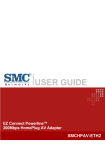
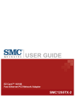
EZConnect Connect EZ N Powerline™ 200Mbps HomePlug AVAdapter Adapter Draft 11n Wireless USB2.0 SMCHPAV-ETH Copyright Information furnished by SMC Networks, Inc. (SMC) is believed to be accurate and reliable. However, no responsibility is assumed by SMC for its use, nor for any infringements of patents or other rights of third parties which may result from its use. No license is granted by implication or otherwise under any patent or patent rights of SMC. SMC reserves the right to change specifications at any time without notice. Copyright © 2009 by SMC Networks, Inc. 20 Mason Irvine, CA 92618 All rights reserved. Printed in Taiwan Trademarks: SMC is a registered trademark; and EZ Connect Powerline is a trademark of SMC Networks, Inc. Other product and company names are trademarks or registered trademarks of their respective holders. 1 Warranty and Product Registration To register SMC products and to review the detailed warranty statement, please refer to the Support Section of the SMC Website at http://www.smc.com SMC Networks, Inc. 20 Mason Irvine, CA 92618 2 Compliances Federal Communication Commission Interference Statement This equipment has been tested and found to comply with the limits for a Class B digital device, pursuant to Part 15 of the FCC Rules. These limits are designed to provide reasonable protection against harmful interference in a residential installation. This equipment generates, uses and can radiate radio frequency energy and, if not installed and used in accordance with the instructions, may cause harmful interference to radio communications. However, there is no guarantee that interference will not occur in a particular installation. If this equipment does cause harmful interference to radio or television reception, which can be determined by turning the equipment off and on, the user is encouraged to try to correct the interference by one or more of the following measures: • Reorient or relocate the receiving antenna. • Increase the distance between the equipment and receiver. • Connect the equipment into an outlet on a circuit different from that to which the receiver is connected. • Consult the dealer or an experienced radio/TV technician for help. This device complies with Part 15 of the FCC Rules. Operation is subject to the following two conditions: (1) This device may not cause harmful interference, and (2) this device must accept any interference received, including interference that may cause undesired operation. FCC Caution: To assure continued compliance, (example - use only shielded interface cables when connecting to computer or peripheral devices) any changes or modifications not expressly approved by the party responsible for compliance could void the user’s authority to operate this equipment. FCC Radiation Exposure Statement: This equipment complies with FCC radiation exposure limits set forth for an uncontrolled environment. This equipment should be installed and operated with a minimum distance of 20cm between the radiator and your body. This transmitter must not be co-located or operating in conjunction with any other antenna or transmitter.. 3 EC Declaration of Conformity SMC contact for these products in Europe is: SMC Networks Spain, S.L. Edificio Conata II, Group CTSG Fructuos Gelabert 6-8 2o2a 08970 Sant Joan Despi, Barcolona,Spain This product indicates compliance with the Essential Requirements of the EMC Directive (2004/108/EC) and the LVD Directive (2006/95/EC) of the European Union. This equipment meets the following conformance standards. EN 55022:2006 CISPR/I/XX/CDV Opt B EN 61000-3-2 : 2006 EN 61000-3-3 : 1995+A1:2001+A2:2005 EN 55024: 1998+A1:2001+A2:2003 IEC 61000-4-2: 1995+A1:1998+A2:2000; IEC 61000-4-3:2006; IEC 61000-4-4: 2004; IEC 61000-4-5: 2005; IEC61000-4-6:2007; IEC61000-4-8:1993+A1:2000; IEC 61000-4-11: 2004 EN 60950-1: 2006 4 Index Preface…………………………………………………………………………............... 6 Important Safety Instructions………………………………………………………… 6 Chapter 1 Installation Notice………………………………….................................. 8 Chapter 2 Product Installation Guide……………………………………………….. 9 2.1 Installing the local powerline network……….……………………………………. 9 2.2 Sharing a xDSL or cable modem Internet connection………………………….. 9 2.3 Extending a wireless network with powerline to share an Internet connection. 10 Chapter 3 Utility…………………………………………………………………………. 11 3.1 System Requirements……………………………………………………………... 11 3.2 Installation…………………………………………………………………………… 11 3.3 Running the Utility………………………………………………………………….. 12 3.4 How to use…………………………………………………………………………... 13 3.4.1 Main Tab………………………………………………………………………… 13 3.4.2 Privacy Tab……………………………………………………………………... 16 3.4.3 Diagnostics Tab………………………………………………………………… 17 3.4.4 About Tab……………………………………………………………………….. 20 Appendix………………………………………………………………………………..... 21 A-1. Specification……………………………….……………………………………….. 21 A-2. Push buttons……………………….………………………………………………. 23 5 PREFACE This document describes the installation of the SMCHPAV-ETH device. Please read this document before installing the product. This publication contains the following sections: Important safety instructions The first thing you need to know before you begin to install Product installation guide Specification IMPORTANT SAFETY INSTRUCTIONS This product is intended for connection to the AC power line. For installation instructions, please refer to the Installation section. For removing the device, refer to the Unplug section. The following precautions should be considered when using this product. z Please read all instructions before installing and operating this product. z Please keep all instructions for later reference. z Please follow all warnings and instructions marked on the product. z Unplug the powerline adapter from the power outlet before cleaning the product. Use a damp cloth for cleaning. DO NOT use liquid or aerosol cleaners. z DO NOT operate this product near water. z This product should never be placed near or over a radiator, or heat register. z This product relies on the building’s electrical installation for short-circuit (over current) protection. z Ensure that a fuse or circuit breaker no larger than 120VAC/20A or 240VAC/16A is used on the phase conductors (all current-carrying conductors). z DO NOT allow anything to rest on the product interconnect cords. DO NOT install this product where people may walk on the cords. z Because the SMCHPAV-ETH device sends data over the powerline, it is recommended that you plug it directly into a power outlet. Do not plug the device into a UPS or power strip with surge protection. The SMCHPAV-ETH device has its own power filter for protection against surges. z The product can be operated at an ambient temperature of 40oC. z For pluggable equipment, the socket-outlet shall be installed near the equipment and shall be easily accessible. 6 z Only a qualified technician should service this product. Opening or removing covers may result in exposure to dangerous voltage points or other risks. z Unplug the powerline adapter from the power outlet and refer the product to qualified service personnel for the following conditions: ¾ When the interconnect cords are damaged or frayed. ¾ If liquid has been spilled into the product. ¾ If the product has been exposed to rain or water. ¾ If the product does not operate normally when the operating instructions are followed. ¾ If the product shows a distinct change in performance. 7 Chapter 1. Installation notice The first thing you need to know before you begin to install…… 1. Before installing, make sure your PC meets these requirements for hardware installation: z Microsoft Windows® 98SE, ME, 2000, XP, Vista, Mac OS or Linux OS z Pentium® III or better, clock rate faster than 2.0GHz recommended z Resource on your PC At least one free Ethernet port for SMCHPAV-ETH device 2. Your PC must not be configured for another network. This means that: z No network clients except for Microsoft Network*, Client for Netware* Networks, or Microsoft Family Logon* are installed z No network services except file and printer sharing for Microsoft Networks or Personal Web Server* are installed z No network protocols except Microsoft’s TCP/IP, IPX/SPX, NetBEUI, or Net BIOS support for IPX/SPX are installed 3. Network installation requires two steps: 1. Install the SMCHPAV-ETH device 2. For each PC to be added to the network, repeat the process 4. Check that you have the following parts for each PC on the network: Quick installation guide for SMCHPAV-ETH device: 1. SMCHPAV-ETH device 2. Ethernet Cable (CAT 5) 5. Familiarize yourself with the Powerline device connections: There is only one Ethernet port. This is used for the connection with PC, xDSL Router, Cable Modem, or Wireless AP. 6. Limitation of the PLC device: To meet the safety regulation, the longest distance between powerline devices is limited to 100 meter and for in-house use only. More than 100 meter will cause the signal reduction or data loss. 8 Chapter 2. Product Installation Guide Important: Do not plug the device into a power strip or surge protector because these devices may consist of filter and impair signal. Also avoid plugging the device right next to noisy sources such as cell phone charger, Halogen light, Energy saving bulb, noisy desktop computer, vacuum cleaner, etc. Both cases result in poor transmission speed. 2.1 Installing the local powerline network 1. Use the supplied Category 5 Ethernet cable to connect the SMCHPAV-ETH to your PC’s Ethernet port. 2. Plug the SMCHPAV-ETH device to an AC power outlet. 3. The Power LED indicator will light on after plugging. 4. You can repeat steps 1 and 2 for connecting the more powerline devices 5. The Link LED indicator starts blinking when the data communication proceeds on the Powerline network. 6. The Ethernet LED indicator starts blinking when the data communication proceeds on the Ethernet network. 2.2 Sharing a xDSL or cable modem Internet connection 1. Connect one SMCHPAV-ETH device to your broadband xDSL/ Cable Router z Plug the SMCHPAV-ETH into an AC power outlet. z Plug the provided Ethernet cable into the RJ45 connector of SMCHPAV-ETH and plug the other end of the cable into an available Ethernet port of the broadband router. 2. Connect the other SMCHPAV-ETH device(s) to the PC(s) to share the Internet connection z Plug the SMCHPAV-ETH device into an AC power outlet. z Plug the provided Ethernet cable into the RJ45 connector of SMCHPAV-ETH and plug the other end of the cable into an available Ethernet port of the PC. 9 2.3 Extending a wireless network with powerline to share an Internet connection 1. Connect one SMCHPAV-ETH device to the broadband router z Plug the SMCHPAV-ETH into an AC power outlet. z Plug the provided Ethernet cable into the RJ45 connector of SMCHPAV-ETH and plug the other end of the cable into an available Ethernet port of the broadband router. 2. Connect the other SMCHPAV-ETH adapter to the wireless Access Point (AP) z Plug the SMCHPAV-ETH device into an AC power outlet. z Plug the provided Ethernet cable into the RJ45 connector of SMCHAV-ETH and plug the other end of the cable into the Ethernet port on the wireless AP. 10 Chapter 3. Utility This Windows utility enables users to find the SMCHPAV-ETH on the Powerline network, measures data transfer rates, ensures privacy and performs diagnostics. 3.1 System Requirements Operation System CPU RAM Free Disk Space Network Interface Microsoft Windows® 2000, XP, Vista Intel Pentium III or better, clock rate faster than 2.0GHz recommended Minimum 128MB Minimum 20MB One Fast Ethernet (10/100Mbps) network card with RJ45 port, one RJ45 Ethernet cable 3.2 Installation Step1. Before installing this utility, please verify that there is no any other Powerline utility installed on your computer. If there is another utility installed, please uninstall it and restart your computer before installing the SMCHPAV-ETH utility. Step 2. Please insert the SMCHPAV-ETH CD-ROM into your computer’s CD-ROM drive. Go to the SMCHPAV-ETH directory and double-click Setup.exe to start the installation. Then the following screens will appear (See Figure 1). Figure 1.Installation Browser Snapshot Step 3. Follow the steps to install this utility by clicking Next >. No password or CD-key is required for installation. 11 3.3 Running the Utility After installing the utility, please run it from the Start/All Programs menu or double click the utility icon on the desktop. Figure 2 shows the main screen of the utility. This screen shows a SMCHPAV-ETH connected as local device and another SMCHPAV-ETH connected as remote device. Figure 2. The Main Tab Screen 12 3.4 How to use 3.4.1. Main Tab The Main tab lists all SMCHPAV-ETH devices that are currently logically connected to the available powerline network. See chapter 3.4.2 on “privacy” to learn more about logical powerline networks. Upper Window The upper window, entitled “Local Device(s) on your computer”, shows all the local SMCHPAV-ETH devices directly connected to your computer via Ethernet. In most cases, there is only one device shown in the upper window. If you have more than one NIC (Network Interface Card) on your computer and each of them connects SMCHPAV-ETH devices, you will find more than one local powerline device shown in the upper window. The utility will scan the Powerline network periodically to search for all SMCHPAV-ETH devices and keep the information updated. 13 CCo MAC Address This window shows the Hardware MAC Address of the “CCo”(Central Coordinator) of this Powerline network. The CCo is automatically appointed by the Powerline network and cannot be changed unless the original CCo is unplugged. Lower Window The lower window lists all the SMCHPAV-ETH devices discovered in the current logical Powerline network. This window will report each powerline device’s connection status, as shown in Figure 2. TEI The TEI shows the unique “Terminal Equipment Identifier” of each SMCHPAV-ETH inside the Powerline network. The TEI is automatically defined by the Powerline network and cannot be changed unless the device is unplugged. Password Shows the password for each SMCHPAV-ETH on the network. You can add or chance the password by selecting a device and clicking the “Enter Password” button. MAC Address Shows the Hardware MAC Address for each SMCHPAV-ETH on the network. Bridged MAC Address Shows the Hardware MAC Adress of the NIC that the SMCHPAV-ETH connects to. If it´s not connected to a NIC, its default value is “ff:ff:ff:ff:ff:ff”. Speed(Mbps) Shows the data transfer speed between the remote device and the local device in Mbps (Million bits per second) “Enter password” button If you’d like to create a secure private network, you need to enter the password for the devices. Please click on the device you want to add a password for and click the “Enter Password” button. The “Set Device Password” dialog box will show up (Figure 3). The TEI and MAC address of the selected device are shown in the dialog box. After entering the password, click “OK” button. You can find the password for each device on the backside of the device. The password typically appears as a number and letter code, in groups of four, separated by dashes. If the input password does not match the device’s real password, an error message will appear and you need to try again. 14 Figure 3. Set Device Password “Add Remote” button The “Add Remote” button is used to add a remote device which is not listed in the lower window to your logical network (for example, a device is currently in another logical network). The dialog box in Figure 4 is shown after clicking the “Add Remote” button, and it allows you to enter both, the device name and the password of the remote device you want to add. The device will be added to your logical network only if the Network Name (see chapter 3.4.2) and Password (see password on the device label) are both correct. Like the “Enter Password” function, incorrect passwords will be warned and denied. Figure 4. Add Remote Device 15 “Scan” button The “Scan” button is used to immediately search for SMCHPAV-ETH devices connected to your logical network. By default setting, it will automatically scan every 10 seconds and update the display lists accordingly. 3.4.2 Privacy Tab By factory default, every SMCHPAV-ETH device carries a default logical network name: “HomePlug AV”. The “Privacy” tab provides functions to manage this logical network name and create private network. “Use Default (Public Network)” button You can directly set the network name back to factory default “HomePlug AV” by clicking the “Use Default (Public Network)” button first, and then clicking the “Set Local Device Only” or “Set All Devices” button. Figure 5. The Privacy Tab Screen 16 “Set Local Device Only” button The “Set Local Device Only” button is used to change the network name of the local device only. After changing the network name to a new one, all the devices existing in the same network before will no longer be able to communicate or respond to you because they will not have the same network name within the local device. “Set All Devices” button The “Set All Devices” button is used to change the network name of all devices in the logical networks, both local and remote, that are shown in the Main Tab. Please enter the password for remote devices in advance, following the instructions in “Enter Password” button to ensure that this function can proceed normally. 3.4.3 Diagnostics Tab The “Diagnostics” tab shows the system information and the history of all devices that have been found before in the logical network (Figure 6). The upper window of the Diagnostics tab shows the host computer’s system information: z MAC Address of all NICs (network interface card) z MAC Address and the firmware version of the SMCHPAV-ETH device which is connected to each NIC. z Computer name z User name z Processor and operating system information z Utility version z Versions of all the driver DLLs and libraries used 17 Figure 6. The Diagnostics Tab Screen The lower window of Diagnostics tab contains the history of all remote devices which have been found by the computer previously. All the devices will be shown here, regardless whether they are currently active or not. The following information is available from the list: z TEI (Terminal Equipment Identifier) z MAC Address z Password z Speed(Mbps) z Last Seen The diagnostics information displayed on the upper and lower window could be saved to a text file or printed out by printers. Devices which no longer exist in the logical network can be deleted using the “Delete…” button. “Delete…”button Select the device that no longer exists in the logical network by clicking its record, and then click this button to delete the record. 18 “View Report…” button Click this button to view all the device information displayed on the upper and lower window in the default text editor. “Save Report…” button Click this button to save all the device information displayed on the upper and lower window to a text file. “Print Report…” button Click this button to print the all diagnostics information to your default printer. 19 3.4.4 About Tab The “About” Tab shows the software version and manufacturer information. Figure 7. The About Tab Screen 20 Appendix A-1.Specification Items Description PHY Rate 200Mbps Effect Data Rate TCP: Up to 65 Mbps effective throughput UDP: Up to 85 Mbps effective throughput Frequency Band 2~28 MHz (With Mask) Access Methods CSMA/CA channel-access schemes Qos z Four-level priority based contention access, and multi segment bursting z 8-levels VLAN priority field, TOS Field z QoS Classification by destination MAC address and IP Port Modulation OFDM (QAM 8/16/64/256/1024, QPSK, BPSK, ROBO) Standards IEEE 802.3, IEEE 802.3u, HomePlug AV 1.1 Operating System Microsoft Windows® 98 SE, Me, 2000, XP, Vista, MacOS, Linux Nodes Up to 63 slaves with 1 master, 64 total devices 4 overlapping networks for neighbor networks with CCo failover Up to 4 masters with up to 252 slaves, 256 total devices in 4 AVLNs Max 64 bridged devices per station Up to 4096 addressable devices including bridged devices IGMP Support for IPv4/IGMPv1,v2,v3 snooping Support for IPv6 and MLDv1,v2 snooping Max 16 source addresses and Group Members Encryption 128-bit AES Link Encryption with key management Push button Security button Reset button Port One 10/100M Ethernet port Distance AC Wire : 100 meters LEDs Power (Red) Link(Green/Orange/Red throughput indicator) Ethernet(Green) Environment Operating : 0~40 ℃ Temperature Storage : -20~60 ℃ Operating : 10~85% Non-Condensing Relative Humidity Storage : 5~90% Non-Condensing Power Source 100 ~ 240 VAC 50/60Hz 21 Power Consumption 4W Max (Normal mode) Below 2W (Standby mode) Certification CE / FCC LEDs Power LED (Red) Link LED (Green/Orange/Red) Ethernet LED (Green) On: Power on Blinking: Standby mode (*1) Off: Power off On: Powerline Link detected and no traffic Blinking: Powerline traffic detected Green: The Powerline connection quality is good Orange: The Powerline connection quality is fair Red: The Powerline connection quality is bad Off: No Powerline Link detected On: Ethernet Link detected Blinking: Ethernet traffic detected Off: No Ethernet Link detected *1: The Power LED indicator will blink in standby mode. It will get into standby mode, if you plug the device to outlet and no Ethernet link detected after booted and 60 second later. If you unplug the Ethernet cable, it will get into standby mode after 60 seconds. Under standby mode, Link LED and Ethernet LED will both be off. 22 A-2. Push buttons Please note that push button functions are disabled in standby mode. ※Security Button Usage: 1. First time to setup your private network: It is highly recommended to setup a private network with encryption to protect the network from unauthorized access through the Powerline network. In a private network each device must use exactly the same private network name to be able to communicate. Step 1. Press and hold the device’s “Security” button for more than 10 seconds to set up a random name for the private network. You can release the button when you see all the device’s LEDs are turned off and on again. The original private network name (HomePlugAV) is cleared. Step 2. Repeat step 1 to clear another device’s original private network name setting. Step 3. Press both devices’ “Security” button for 2 seconds. You will see both devices’ “Power” LED start blinking. The devices start to communicate and try to setup their private network name. They will complete the process within 10 seconds. On both devices’ all LEDs are turned off and on again. Note: The setup operation timeout is 120 seconds. Step 4. If the process to setup your private network failed, please repeat step 1 to step 3 again. 2. Add a new device to an existing private network: Step 1. Press and hold the “Security” button of the new device for more than 10 seconds to clear the original private network name setting. Step 2. Press the new device’s “Security” button for 2 seconds. The “Power” LED starts blinking. Step 3. Select a random device from the existing private network. Press its “Security” button for 2 seconds. The device’s “Power” LED starts blinking. 23 Step 4. The new device starts to communicate with the device from the existing private network, and tries to join the existing private network. It will complete the process within 10 seconds. On the new device’s all LEDs are turned off and on again. The existing private network device’s “Power” LED become solid. Note: The setup operation timeout is 120 seconds. Step 5. If the process to add a new device to an existing private network failed, please repeat step 1 to step 3 again. 3. Remove a device from an existing private network: To remove a device from existing network, press and hold the device’s “Security” button for more than 10 seconds to clear the private network name setting and generate a new random private network name. This will remove the device from the existing private network. To recover the private network name back to default, a hardware reset is required. Please press reset button. ※Reset Button Usage: 1. Reset the device to the factory default setting: Press the device’s “Reset” button for 2 seconds. You will see all the device’s LEDs are off and restart. The device’s setting will reset to the “factory defaults”. 24 SMCHPAV-ETH