1
®
Dolphin
7600 Mobile Computer
with Windows Mobile® 6
User’s Guide
Disclaimer
Honeywell International Inc. (“HII”) reserves the right to make changes in specifications and other
information contained in this document without prior notice, and the reader should in all cases consult HII
to determine whether any such changes have been made. The information in this publication does not
represent a commitment on the part of HII.
HII shall not be liable for technical or editorial errors or omissions contained herein; nor for incidental or
consequential damages resulting from the furnishing, performance, or use of this material.
This document contains proprietary information that is protected by copyright. All rights are reserved. No
part of this document may be photocopied, reproduced, or translated into another language without the
prior written consent of HII.
Web Address: www.honeywellaidc.com
Trademarks
Dolphin, Dolphin RF, HomeBase, Mobile Base, and QuadCharger are trademarks or registered
trademarks of Hand Held Products, Inc. or Honeywell International Inc.
Microsoft, Windows, Windows Mobile, Windows CE, Windows NT, Windows 2000, Windows ME,
Windows XP, ActiveSync, Outlook, and the Windows logo are trademarks or registered trademarks of
Microsoft Corporation.
Other product names mentioned in this manual may be trademarks or registered trademarks of their
respective companies and are the property of their respective owners.
Patents
Please refer to the product packaging for a list of patents.
Other Trademarks
The Bluetooth trademarks are owned by Bluetooth SIG, Inc., U.S.A. and licensed to Honeywell
International Inc.
microSD and microSDHC are trademarks.
©2008–2009 Honeywell International Inc. All rights reserved.
Table of Contents
Chapter 1 - Agency Approvals
Label Locations ....................................................................................................................1-1
LED Safety Statement....................................................................................................1-1
FCC RF Radiation Exposure Statement ........................................................................1-1
R&TTE Compliance Statement—802.11b/g, Bluetooth, and/or GSM..................................1-2
Dolphin RF Terminal—802.11b/g, Bluetooth, and/or GSM ..................................................1-3
For European Community Users .........................................................................................1-3
Waste Electrical and Electronic Equipment Information ......................................................1-4
Chapter 2 - Getting Started
Out of the Box ......................................................................................................................2-1
Today Screen.......................................................................................................................2-2
Navigation Bar and Start Menu ............................................................................................2-2
Icons in the Navigation Bar ............................................................................................2-3
Command Bar ......................................................................................................................2-4
Selecting Programs..............................................................................................................2-5
Using the Stylus ...................................................................................................................2-5
Chapter 3 - Hardware Overview
Standard Configurations ......................................................................................................3-1
Hardware Features ........................................................................................................3-1
Peripherals ...........................................................................................................................3-2
Accessories..........................................................................................................................3-2
Front Panel Features ...........................................................................................................3-3
Touch Screen Display ..........................................................................................................3-4
Display Backlight............................................................................................................3-4
Using Screen Protectors ................................................................................................3-4
Back Panel Features..........................................................................................................3-10
Using the Accessory Attachment .................................................................................3-11
Side Panel Features ..........................................................................................................3-12
Installing Memory Cards ..............................................................................................3-13
Bottom Panel Features ......................................................................................................3-15
Connecting the USB Cable ..........................................................................................3-16
ActiveSync Communication ...............................................................................................3-18
Battery Power ....................................................................................................................3-21
Checking Battery Power...............................................................................................3-24
Resetting the Terminal .......................................................................................................3-25
Soft Reset (Warm Boot) ...............................................................................................3-25
Hard Reset (Cold Boot)................................................................................................3-25
Suspend Mode ...................................................................................................................3-26
iii
Chapter 4 - Using the Keyboards
Overview.............................................................................................................................. 4-1
29-Key Numeric Keyboard............................................................................................. 4-1
38-Key Alpha Keyboard................................................................................................. 4-1
Suspend/Resume .......................................................................................................... 4-1
Function Keys ................................................................................................................ 4-2
Modifier Keys ................................................................................................................. 4-2
Alpha/Numeric Indicator ................................................................................................ 4-3
29-Key Numeric Keyboard .................................................................................................. 4-4
Navigation Keys............................................................................................................. 4-4
Hardware Application Buttons ....................................................................................... 4-5
Toggling Between Alpha and Numeric Modes............................................................... 4-6
29-Key Blue Key Combinations (Alpha Mode) .............................................................. 4-7
29-Key Shift Functionality in Numeric Mode.................................................................. 4-7
29-Key Red Key Combinations...................................................................................... 4-8
38-Key Alpha Keyboard..................................................................................................... 4-10
Toggling Between Alpha and Numeric Modes............................................................. 4-10
38-Key Red Key Combinations.................................................................................... 4-11
38-Key NUM Lock Mode ............................................................................................. 4-12
Chapter 5 - Using the Image Engine
Overview.............................................................................................................................. 5-1
Available Engines ................................................................................................................ 5-1
Supported Bar Code Symbologies ..................................................................................... 5-2
Activating the Engine........................................................................................................... 5-3
Decoding ............................................................................................................................. 5-3
Capturing Images ................................................................................................................ 5-5
Chapter 6 - System Settings
Overview.............................................................................................................................. 6-1
Personal Tab ....................................................................................................................... 6-2
Buttons........................................................................................................................... 6-3
Input............................................................................................................................... 6-4
Menus ............................................................................................................................ 6-5
iv
System Tab ......................................................................................................................... 6-7
About ............................................................................................................................. 6-7
Backlight ........................................................................................................................ 6-8
Certificates..................................................................................................................... 6-8
ClearType Tuner............................................................................................................ 6-8
Clock & Alarms .............................................................................................................. 6-9
Encryption...................................................................................................................... 6-9
Error Reporting .............................................................................................................. 6-9
External GPS ............................................................................................................... 6-10
Memory........................................................................................................................ 6-10
Power........................................................................................................................... 6-12
Regional Settings......................................................................................................... 6-12
Remove Programs....................................................................................................... 6-13
Screen ......................................................................................................................... 6-14
WAN Info ..................................................................................................................... 6-15
Chapter 7 - Connecting the Terminal
Connections Tab ................................................................................................................. 7-1
Infrared Communication ...................................................................................................... 7-2
IrDA Port Location ........................................................................................................ 7-2
Sending Data ................................................................................................................. 7-2
Receiving Data .............................................................................................................. 7-3
Connections Manager ......................................................................................................... 7-4
Task Tab........................................................................................................................ 7-4
Advanced Tab................................................................................................................ 7-5
Dolphin Wireless Manager .................................................................................................. 7-6
Dolphin Wireless Manager Window............................................................................... 7-6
Enabling the Radios....................................................................................................... 7-6
Accessing Radio Configuration Utilities ......................................................................... 7-7
Icons in the Navigation Bar............................................................................................ 7-7
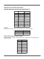
COM Port Assignment Table............................................................................................... 7-8
7600 with Windows Mobile Professional (with GSM): .................................................. 7-8
7600 with Windows Mobile Classic (without GSM): ...................................................... 7-8
Network Cards..................................................................................................................... 7-9
USB to PC ......................................................................................................................... 7-10
Installing Additional Software ............................................................................................ 7-11
Adding Programs via ActiveSync................................................................................. 7-11
Adding Programs From the Internet ............................................................................ 7-12
Chapter 8 - Working with GSM
Overview.............................................................................................................................. 8-1
Antenna ......................................................................................................................... 8-1
Icons in the Navigation Bar............................................................................................ 8-2
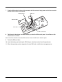
SIM Card Installation ........................................................................................................... 8-2
To Install a SIM Card ..................................................................................................... 8-2
Enabling the GSM Radio ..................................................................................................... 8-4
Data Communication ........................................................................................................... 8-5
Establishing Data Communication................................................................................. 8-5
Ending the Data Connection.......................................................................................... 8-7
v
Voice Communication.......................................................................................................... 8-8
Audio Modes.................................................................................................................. 8-8
Accessing the Dialer Window ........................................................................................ 8-9
Keyboard Combinations for Sending and Ending Calls................................................. 8-9
Setup Options.................................................................................................................... 8-10
Roaming ............................................................................................................................ 8-11
Chapter 9 - Working with the Bluetooth Radio
Enabling the Bluetooth Radio .............................................................................................. 9-1
Icons in the Navigation Bar............................................................................................ 9-1
Connecting to Other Bluetooth Devices .............................................................................. 9-2
Pairing and Trusted Devices ............................................................................................... 9-4
Types of Devices and Services ........................................................................................... 9-5
Connecting to Bluetooth Printers......................................................................................... 9-6
Connecting to Bluetooth Headsets ...................................................................................... 9-6
Transferring Files................................................................................................................. 9-7
Making the Terminal Discoverable ...................................................................................... 9-8
Chapter 10 - Dolphin 7600 with GPS
Overview............................................................................................................................ 10-1
GPS Functionality ........................................................................................................ 10-1
Powering the GPS Module ................................................................................................ 10-1
Suspend/Resume with GPS .............................................................................................. 10-2
Suspend Via Keyboard Combination........................................................................... 10-2
Suspend Via Activity timeout ....................................................................................... 10-2
Time to First Fix (TTFF)..................................................................................................... 10-2
Typical TTFF From No Satellite Data .......................................................................... 10-2
Serial Communications...................................................................................................... 10-3
GPS Demo ........................................................................................................................ 10-3
Chapter 11 - Dolphin HomeBase Device
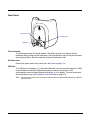
Overview............................................................................................................................ 11-1
Front Panel ....................................................................................................................... 11-2
Back Panel ....................................................................................................................... 11-3
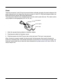
Power ................................................................................................................................ 11-4
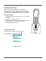
Charging the Main Battery................................................................................................. 11-5
Mounting............................................................................................................................ 11-6
Bottom Panel Dimensions ................................................................................................. 11-7
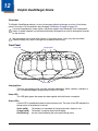
Chapter 12 - Dolphin QuadCharger Device
Overview............................................................................................................................ 12-1
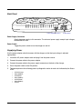
Front Panel ....................................................................................................................... 12-1
Back Panel ........................................................................................................................ 12-2
Supplying Power................................................................................................................ 12-2
Battery Charging................................................................................................................ 12-3
Recommendations for Storing Batteries............................................................................ 12-3
Mounting............................................................................................................................ 12-4
Troubleshooting................................................................................................................. 12-6
vi
Chapter 13 - Dolphin Mobile Mount
Overview............................................................................................................................ 13-1
Inserting a Terminal ..................................................................................................... 13-1
Mounting............................................................................................................................ 13-3
Chapter 14 - Technical Specifications
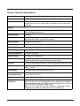
Terminal Technical Specifications ..................................................................................... 14-1
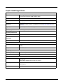
Dolphin HomeBase Device................................................................................................ 14-3
Dolphin QuadCharger Device............................................................................................ 14-4
Chapter 15 - Customer Support
Technical Assistance......................................................................................................... 15-1
Online Technical Assistance........................................................................................ 15-1
Product Service and Repair............................................................................................... 15-1
Online Product Service and Repair Assistance ........................................................... 15-2
Limited Warranty ............................................................................................................... 15-3
How to Extend Your Warranty ..................................................................................... 15-4
..................................................................................................................................... 15-4
vii
viii
1
Agency Approvals
Label Locations
Dolphin 7600 terminals meet or exceed the requirements of all applicable standards organizations for
safe operation. However, as with any electrical equipment, the best way to ensure safe operation is to
operate them according to the agency guidelines that follow. Please read these guidelines carefully
before using your Dolphin terminal.
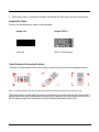
Compliance Label
Molded-in Text
(see page 1-1)
Molded-in Text
This Class B Digital Device Complies with
Canadian ICES-003. Cet appareil numerique
de la Classe B est conforme a la norme
NMB-003 du Canada.
See
Manual
!
Laser Safety Label
If the following label is attached to your product, it indicates the product
LASER LIGHT. DO NOT STARE INTO BEAM.
contains a laser engine or laser aimer:
CLASS 2 LASER PRODUCT
1.0 mW MAX OUTPUT: 650nM
IEC60825-1: 1993+A1+A2
Laser Eye Safety Statement: This device has been tested in accordance
with 21 CFR 1040.10 and 1040.11
with and complies with IEC60825-1: 1993+A1+A2 and 21 CFR 1040.10 and Complies
except for deviations pursuant to Laser
1040.11, except for deviations pursuant to Laser Notice No. 50, dated July
Notice No. 50, dated June 24, 2007.
26, 2001. LASER LIGHT, DO NOT STARE INTO BEAM, CLASS 2 LASER
PRODUCT, 1.0 mW MAX OUTPUT: 650nM.
Caution - use of controls or adjustments or performance of procedures other than those specified herein
may result in hazardous radiation exposure.
LED Safety Statement
The LED output on this device has been tested in accordance with IEC60825-1 LED safety and certified
to be a Class 1 LED device.
FCC RF Radiation Exposure Statement
This equipment complies with FCC RF radiation exposure limits set forth for an uncontrolled environment.
This device has been tested and meets the FCC RF exposure guidelines for body worn operation only.
An accessory must be used for body worn operation. This device is not intended to be held next to the
head for voice communication.
1-1
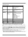
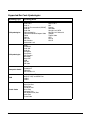
Approvals by Country
Country
Safety
EMC, Radio, & SAR
U.S.A.
UL60950-1
FCC Part 15, Subpart C, 15.247
FCC Part 15, Subpart B
FCC Part 22H
FCC Part 24H
FCC SAR OET 65 Supplement C
Canada
cUL60950
ICES-003 (Class B)
RSS 132
RSS 133
European
Community/CE
EN/IEC60950-1:2000
EN60825-1:1994 + A11
+ A2
IEC60825-1
EN 300328-1/2
EN55022:1998+A1:2000+A2:2003
EN55024:1998+A1:2001+A2:2003
EN301 511
EN301 489-1/-7
EN301 489-17
EN61000-3-2:2000
EN61000-3-3:1995+A1-2001
EN60360 June 2001
EN50361 June 2001
EN50371 June 2001
Turkey
EN60950
CE/EMC
South Africa
N/A
ICASA
ANATEL
Brazil
Mexico
NOM
COFETEL
Russia
GOST-R
Russian Telecom. type approval cetificate
R&TTE Compliance Statement—802.11b/g, Bluetooth, and/or GSM
Dolphin RF terminals are in conformity with all essential requirements of the R&TTE Directive (1999/5/
EC).
This product is marked with
0678 in accordance with the Class II product requirements specified
in the R&TTE Directive. In addition, this product complies to 2006/95/EC Low Voltage Directive when
supplied with the recommended power supply. Honeywell shall not be liable for use of our product with
equipment (i.e., power supplies, personal computers, etc.) that is not CE marked and does not comply
with the Low Voltage Directive.
The equipment is intended for use throughout the European Community; PAN European Frequency
Range: 2.402–2.480 GHz. Restrictions for use in France are as follows:
• Indoor use: Maximum power (EIRP*) of 100 mW for the entire 2.400–2.4835 GHz
• Outdoor use: Maximum power (EIRP*) of 100 mW for the 2.400–2.454 GHz band & maximum power
(EIRP*) of 10 mW for the 2.454–2.483 MGHz band.
1-2
For further information, please contact:
Hand Held Products BV, a wholly owned subsidiary of Honeywell International Inc.
Nijverheidsweg 9
5627 BT Eindhoven
The Netherlands
Dolphin RF Terminal—802.11b/g, Bluetooth, and/or GSM
This device complies with Part 15 of the FCC Rules. Operation is subject to the following two conditions:
(1) this device may not cause harmful interference, and (2) this device must accept any interference
received, including interference that may cause undesired operation.
This equipment has been tested and found to comply with the limits for a Class B digital device pursuant
to Part 15 of the FCC Rules. These limits are designed to provide reasonable protection against harmful
interference in a residential installation. This equipment generates, uses, and can radiate radio frequency
energy and, if not installed and used in accordance with the instructions, may cause harmful interference
to radio communications. However, there is no guarantee that interference will not occur in a particular
installation. If this equipment does cause harmful interference to radio or television reception, which can
be determined by turning the equipment off and on, the user is encouraged to try to correct the
interference by one or more of the following measures:
• Reorient or relocate the receiving antenna.
• Increase the separation between the equipment and receiver.
• Connect the equipment into an outlet on a circuit different from that to which the receiver is connected.
• Consult the dealer or an experienced radio/TV technician for help.
If necessary, the user should consult the dealer or an experienced radio/television technician for
additional suggestions. The user may find the following booklet helpful: “Something About Interference.”
This is available at FCC local regional offices. Our company is not responsible for any radio or television
interference caused by unauthorized modifications of this equipment or the substitution or attachment of
connecting cables and equipment other than those specified by our company. The correction is the
responsibility of the user. Use only shielded data cables with this system.
In accordance with FCC 15.21, changes or modifications not expressly approved by the party responsible
for compliance could void the user’s authority to operate the equipment.
CAUTION!
Any changes or modifications not expressly approved by the grantee of this device
could void the user's authority to operate the equipment.
Canadian Compliance
This Class B digital apparatus complies with Canadian ICES-003. Operation is subject to the following
two conditions: (1) this device may not cause harmful interference, and (2) this device must accept any
interference received, including interference that may cause undesired operation.
To prevent radio interference to the licensed service, this device is intended to be operated indoors and
away from windows to provide maximum shielding. Equipment (or its transmit antenna) installed outdoors
is subject to licensing.
Cet appareil numérique de la Classe B est conforme à la norme NMB-003 du Canada.
For European Community Users
Honeywell complies with Directive 2002/96/EC OF THE EUROPEAN PARLIAMENT AND OF THE
COUNCIL of 27 January 2003 on waste electrical and electronic equipment (WEEE).
1-3
Waste Electrical and Electronic Equipment Information
This product has required the extraction and use of natural resources for its production. It may contain
hazardous substances that could impact health and the environment, if not properly disposed.
In order to avoid the dissemination of those substances in our environment and to diminish the pressure
on the natural resources, we encourage you to use the appropriate take-back systems for product
disposal. Those systems will reuse or recycle most of the materials of the product you are disposing in a
sound way.
The crossed out wheeled bin symbol informs you that the product should not be disposed of along
with municipal waste and invites you to use the appropriate separate take-back systems for product
disposal.
If you need more information on the collection, reuse, and recycling systems, please contact your local or
regional waste administration.
You may also contact your supplier for more information on the environmental performances of this
product.
ANATEL
Este produto está homologado pela ANATEL, de acordo com
os procedimentos regulamentados pela Resolução 242/2000, e
atende aos requisitos técnicos aplicados.
Para maiores informações, consulte o site da ANATEL www.anatel.gov.br.
Este equipamento opera em caráter secundário, isto é, não tem
direito a proteção contra interferência prejudicial, mesmo de
estações do mesmo tipo, e não pode causar interferência a
sistemas operando em caráter primário.
1866-08-4741
Pacemakers, Hearing Aids and Other Electrically Powered Devices
Most manufacturers of medical devices adhere to the IEC 601-1-2 standard. This standard requires
devices to operate properly in an EM Field with a strength of 3V/m over a frequency range of 26 to
1000MHz. The maximum allowable field strength emitted by the Dolphin is 0.3V/m according to Subpart
B of Part 1 of the FCC rules. Therefore, the Dolphin RF has no effect on medical devices that meet the
IEC specification.
Microwaves
The radio in the Dolphin RF terminal operates on the same frequency band as a microwave oven.
Therefore, if you use a microwave within range of the Dolphin RF terminal you may notice performance
degradation in your wireless network. However, both your microwave and your wireless network will
continue to function. The Dolphin Batch terminal does not contain a radio, and therefore, is not affected
by microwave ovens.
1-4
2
Getting Started
Out of the Box
Verify that your carton contains the following items:
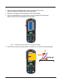
• Dolphin 7600 mobile computer (the terminal)
• Main battery pack (3.7v, Li-ion)
• AC power supply
• Localized plug adapters
• User CD
Note: Be sure to keep the original packaging in case you need to return the Dolphin terminal for service; see Limited
Warranty on page 15-3.
Step 1. Install the Main Battery
!
We recommend use of Hand Held Products Li-Ion battery packs. Use of any non-Hand Held
Products battery may result in damage not covered by the warranty.
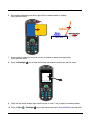
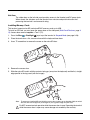
Step 2. Charge the Batteries
Dolphin terminals ship with both the main battery
pack and internal backup battery significantly
discharged of power. Charge the main battery
pack with the charging cable for a minimum of
four hours before initial use.
1. Attach the appropriate plug adapter to the
plug of the power cable.
1
Power Cable
2. Plug the *power cable into the DC Power Jack
(see page 3-12) on the left side.
3. Insert the plug into the appropriate power
source.
*This power cable can also be used to power the
Dolphin HomeBase Device (see page 11-1).
!
2
We recommend use of Hand Held Products peripherals, power cables, and power adapters. Use of any nonHand Held Products peripherals, cables, or power adapters may cause damage not covered by the warranty.
2-1
Step 3. Boot the Terminal
The terminal begins booting as soon as power is applied and runs by itself. Do NOT press any keys or
interrupt the boot process. Only tap the screen when prompted. When the boot process is complete, the
Today Screen (see page 2-2) appears and the terminal is ready for use.
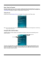
Today Screen
System resets (see Resetting the Terminal on page 3-25) complete on the Today screen.
Note: You can access the Today screen any time by tapping the Start button on the Navigation bar and selecting
Today in the drop-down list.
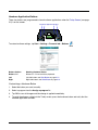
Navigation Bar and Start Menu
Located at the top of every window, the Navigation bar displays various icons representing various
system functions.
Navigation Bar
Start Menu
The icons in the table below may appear in the Navigation bar. Which icons appear depend on your
terminal’s configuration; for example, if the terminal does not have a GSM radio, then the icons that
pertain to the GSM radio won’t appear. If the terminal does have a GSM radio, then those icons will
appear according to system functions.
2-2
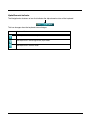
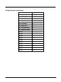
Icons in the Navigation Bar
Indicator
Meaning
The terminal could not synchronize data with the workstation via ActiveSync
New e-mail or text message (SMS)
New voicemail
New instant message
Ringer off
Voice call
Voice call in progress
Calls are forwarded
Call on hold
Missed call
Data call in progress
Battery levels (1–4). Tap this icon to open the Power system setting and see the charge
percentage (see page 6-12).
Critical battery. The charge percentage is at the critical battery point set in the registry (the
default is 10%). For details about the critical battery point, (see page 3-22).
Tap this icon to open the Power system setting and see the charge percentage (see page 612).
Terminal is running on external power (If a battery pack is installed, that battery is charging.)
The terminal is not connected to external power. A battery is installed but is defective;
specifically, its charge level cannot be measured.
No SIM card is installed
GPRS available
GPRS connected
EDGE available
EDGE connected
2-3
Icons in the Navigation Bar
Indicator
Meaning
Roaming
Radio is disabled
The radio is not connected to a network
Radio connected
No radio signal
The terminal is searching for a signal
Radio signal strength
Wi-Fi on
Wi-Fi data call
Pending alarm
Bluetooth
Command Bar
Located at the bottom of the Today screen, the command bar displays running applications.
This area displays various icons that access
applications running on the terminal. Use the right
and left arrows to navigate through these icons.
2-4
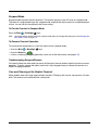
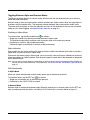
Selecting Programs
Tapping Start opens the drop-down menu, which provides access to the most common system functions
and programs. To open a program, tap Start > Programs. Then, tap the program icon on the menu.
Using the Stylus
The terminal comes with a stylus inserted into the Stylus Slot (see page 3-10), Use this stylus (or your
finger) to select or enter information on the touch screen. The stylus functions as a mouse; generally, a
tap is the same as a click.
Tap
Tap the touch screen once to open menu items and select options.
Drag
Hold the stylus on the screen and drag across the screen to select text and images.
Tap & hold
Tap and hold the stylus on an item and a pop-up menu appears. On the pop-up menu, tap
the action of the task you want to perform.
!
Use of other objects other than the stylus, such as paper clips, pencils, or ink pens can damage the touch
screen and may cause damage not covered by the warranty.
For more information about the touch screen, see Touch Screen Display on page 3-4.
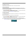
Using File Explorer
Use File Explorer to navigate through the files on your terminal. Tap Start > Programs > File Explorer.
Move files by tapping and holding on the file, then tapping Cut, Copy or Paste on the pop-up menus that
appear.
Pop-Up Menus
With pop-up menus, you can quickly choose an action for an item.
1. Tap and hold the stylus on the item name. The pop-up menu appears.
2.
Lift the stylus, and tap the action you want to perform.
Note: The contents of pop-up menus change according to the program you’re in.
2-5
2-6
3
Hardware Overview
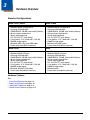
Standard Configurations
WPAN / WLAN / WWAN
WPAN / WWAN
•
•
•
•
•
•
•
•
•
•
•
•
•
Windows Mobile 6 Professional
Samsung 2440 400 MHz
128MB RAM X 128 MB (non-volatile) Memory
29-key numeric keyboard or
38-key alpha keyboard
2.8” 1/4 VGA TFT color display
Li-ion battery: 3.7V / 3240 mAh / 12.0 Wh
5300SR image engine
Bluetooth, 802.11b/g, and GSM radios
Power cable (included in each box)
•
•
•
•
•
Windows Mobile 6 Professional
Samsung 2440 400 MHz
128MB RAM X 128 MB (non-volatile) Memory
29-key numeric keyboard or
38-key alpha keyboard
2.8” 1/4 VGA TFT color display
Li-ion battery: 3.7V / 3240 mAh / 12.0 Wh
5300SR image engine
Bluetooth and GSM radios
Power cable (included in each box)
WPAN / WLAN
WPAN
•
•
•
•
•
•
•
•
•
•
•
•
•
Windows Mobile 6 Classic
Samsung 2440 400 MHz
128MB RAM X 128 MB (non-volatile) Memory
29-key numeric keyboard or
38-key alpha keyboard
2.8” 1/4 VGA TFT color display
Li-ion battery: 3.7V / 3240 mAh / 12.0 Wh
5300SR image engine
Bluetooth and 802.11b/g radios
Power cable (included in each box)
•
•
•
•
•
Windows Mobile 6 Classic
Samsung 2440 400 MHz
128MB RAM X 128 MB (non-volatile) Memory
29-key numeric keyboard or
38-key alpha keyboard
2.8” 1/4 VGA TFT color display
Li-ion battery: 3.7V / 3240 mAh / 12.0 Wh
5300SR image engine
Bluetooth radio
Power cable (included in each box)
Hardware Features
See
• Front Panel Features on page 3-3
• Back Panel Features on page 3-10
• Side Panel Features on page 3-12
• Bottom Panel Features on page 3-15
3-1
Peripherals
The following items are sold separately and enhance the capabilities of your Dolphin terminal.
Dolphin HomeBase™ Device
The Dolphin HomeBase device is a charging and communication cradle. There are two versions of this
device: one that supports USB and another that supports RS-232 communication. These two options
enable your terminal to interface with the majority of PC-based enterprise systems. When a terminal is
seated in a powered base, its main battery pack charges in less than four hours.
For more information, see Dolphin HomeBase Device on page 11-1.
Dolphin QuadCharger™ Device
The Dolphin QuadCharger device is a four-slot charging station for Li-ion battery packs that can charge
each battery in less than four hours.
For more information, see Dolphin QuadCharger Device on page 12-1.
Accessories
Each of the following items is sold separately to enhance your Dolphin terminal’s capabilities.
Protective Enclosure
This enclosure wraps around the terminal to protect it from wear and tear.
Li-ion Battery Packs
The available Li-ion battery packs provide the main power supply for the terminal.
For more information, see Battery Power on page 3-21.
3-2
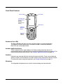
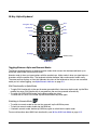
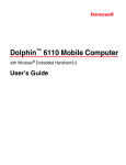
Front Panel Features
Decode LED
Scan LED
1/4 VGA Touch
Screen Display
(screen
protector
installed at the
factory)
Microphone
Hardware
Application
Buttons
Keyboard
(29-key
numeric)
Decode and Scan LEDs
The Scan LED lights red when you press the Scan trigger in scanning applications.
The Decode LED lights green when a scanned bar code is successfully decoded.
Both LEDs are user-programmable.
Hardware Application Buttons
These hardware buttons appear only on the 29-key numeric keyboard and can be
programmed to perform software functions available in the Buttons setting (see page 6-3). For
more information about these buttons, see Hardware Application Buttons on page 4-5.
Keyboard
Keyboards are recessed within the housing to increase durability. There are two keyboard
options available: one that defaults to numeric (shown above) and one that defaults to alpha.
For information about using both keyboards, see Using the Keyboards on page 4-1.
Microphone
The integrated microphone can be used for voice recording and communication.
3-3
Touch Screen Display
The display is a 65,536-color LCD (Liquid Crystal Display) covered by a touch screen lens. The 2.8” 1/4
VGA (Video Graphic Array) is TFT (Thin Film Transistor) color, backlit, and the resolution is 240 x 320;
see Display Backlight on page 3-4.
Dolphin terminals ship with a screen protector already installed over the touch screen lens to help
prevent damage to the touch screen. Do NOT remove this screen protector before initial use.
! Honeywell recommends using screen protectors, especially for applications that require highvolume interfacing with the touch screen. For more information, see Using Screen Protectors on
page 3-4.
For touch screen input, use the stylus included with the terminal or your finger. The method you choose
depends on which one is most appropriate for your application. While there is a great deal of variation in
different applications, for buttons or icons that are close together, you generally achieve greater accuracy
with the stylus; see Using the Stylus on page 2-5.
!
Use of objects, such as paper clips, pencils, or ink pens on the touch screen can damage the input panel and
may cause damage not covered by the warranty.
Display Backlight
The touch screen display has a backlight that is programmed to turn off after a specified period of time
that the terminal is idle. For details, see Backlight on page 6-8.
Using Screen Protectors
Honeywell defines proper use of the terminal touch panel display as using a screen protector and proper
stylus. Screen protectors maintain the ongoing integrity (i.e., prevent scratching) of the touch panel, which
is why their use is recommended for applications that require a high to medium level of interface with the
touch panel.
Honeywell continues to advocate the use of screen protectors on all Dolphin terminals. We recommend
implementing a screen protector replacement program to ensure that screen protectors are replaced
periodically when signs of damage/wear are noticeable. For general use, we recommend replacing the
screen protector every thirty (30) days. However, replacement cycles vary according to the average level
of touch panel use in your application.
Replacement screen protectors can be purchased directly from Honeywell. Please contact a Honeywell
sales associate for details.
Honeywell also mandates use of a proper stylus, which is one that has a stylus tip radius of no less than
0.8mm. Use of the Honeywell stylus included with the terminal is recommended at all times.
Honeywell warranty policy covers wear on the touch panel display for the first 12 months provided that a
screen protector is applied and an approved stylus is used for the 12 month duration covered by the
warranty.
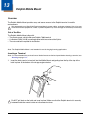
Removing the Screen Protector
Dolphin terminals ship with a touch screen protector already installed. To replace the screen protector,
you must remove the one already installed.
3-4
1.
You will need a strong, flat, plastic card (a credit card, for example) to wedge under the existing
screen protector.
Note: If you have one, you can also use the small plastic squeegees designed for touch panels.
2.
Press the Blue
+ Backlight
keys to put the terminal in Suspend Mode (see page 3-26).
3.
Carefully apply the flat edge of your plastic card to the upper right corner of the touch screen.
Catch the edge of the screen protector and pull it up and away from the touch panel.
Touch Panel
3-5
4.
Wipe the screen with a clean, non-abrasive, lint-free cloth.
Note: Use ionized air, if available, to blow additional dirt or particles off the touch panel.
Installing Your Screen Protector
When installing a new screen protector, use a flat plastic card (such as a credit card) to apply the screen
protector smoothly and remove any air bubbles.
Note: If you have one, use the small plastic squeegees designed for touch panels.
1.
3-6
Press the Blue
+ Backlight
keys to put the terminal in Suspend Mode (see page 3-26).
2.
Clean the touch panel thoroughly with a clean, non-abrasive, lint-free cloth.
Make sure nothing is attached to the top of the touch panel.
3.
Release the left edge of the releasing paper on the screen protector.
4.
Align the exposed edge of the screen protector along the left edge of the touch panel.
Make sure that it lies flush with edges of the touch panel.
Note: To reposition the screen protector, lift up gently and reapply.
5.
Use the card on top of the screen protector to it smooth out as you pull on the releasing paper.
Touch Panel
3-7
6.
Pull smoothly and evenly from left to right until the screen protector is applied.
Press gently but firmly.
Touch Panel
7.
Use the card as necessary to smooth out any air pockets or bumps after application.
Press gently but firmly.
8.
Press the Backlight
9.
Verify that the screen accepts input from the stylus as usual. If not, re-apply the screen protector.
10. Press the Blue
3-8
key to wake the terminal and check the touch panel with the stylus.
+ Backlight
keys to put the terminal back in Suspend Mode (see page 3-26).
11. Clean the surface of the screen protector with a clean, non-abrasive, lint-free cloth.
12. Press the Backlight
key to wake the terminal.
13. For maximum performance, recalibrate the screen. Tap Start > Settings > System tab > Screen
> Align Screen.
14. Follow the instructions on the screen.
3-9
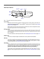
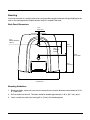
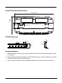
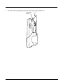
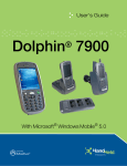
Back Panel Features
Image Engine Window
Stylus Slot
Accessory Attachment
Rear Speaker
Finger Saddle
SIM Card Door
I/O Connector
Accessory Attachment
Use this button to attach accessories; see Using the Accessory Attachment on page 3-11.
Finger Saddle
This is a slightly depressed and angled area of the back panel that is designed to cradle or
“saddle” your pointer finger while holding the terminal. This unique ergonomic design makes
the terminal comfortable to hold and helps prevent you from accidentally dropping the terminal.
Rear Speaker
The integrated speaker sounds audio signals as you scan bar code labels and enter data but
emits no ambient noise on system activity such as processor activity, memory access, radio
traffic, etc. The speaker can also be used for playing sounds (e.g., WAV or MP3 files).
The rear speaker also receives audio signals during voice communication over a GSM
network. For more information, see Speakerphone on page 8-8.
SIM Card Door
Access to the SIM card slot is under this door, which is under the battery. You must open this
door to insert or remove a SIM card. For details, see SIM Card Installation on page 8-2.
Stylus Slot
Dolphin terminals ship with a stylus inserted in the back panel. Store the stylus in this slot when
you’re not using it. For details, see Using the Stylus on page 2-5.
3 - 10
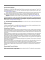
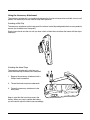
Using the Accessory Attachment
The accessory attachment is a standard tab designed to fit universal accessories available for most cell
phones. An accessory must be used for body worn operation.
Attaching a Belt Clip
The accessory attachment on the back panel fits universal swivel clips designed for belts or even pedestal
mounts (not available from Honeywell).
Simply insert the tab into the slot until you hear a click or follow the instructions that came with the clip or
accessory.
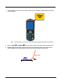
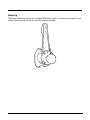
Attaching the Hand Strap
The accessory attachment is also how you
attach the hand strap available from Honeywell.
1.
Remove the accessory attachment with a
Phillips head screwdriver.
2.
Thread the hand strap hook underneath.
3.
Fasten the accessory attachment to the
back panel.
Keep in mind that the hand strap covers the
battery. When you want to replace the battery,
you will need to adjust the hand strap accordingly.
3 - 11
Side Panel Features
DC Power
Jack
Headset
Jack
IrDA Port
Side
Button
Access
Door
Side Door
Note:
This graphic shows the left side of the terminal.
Access Door
This door covers the memory card slot. To increase memory, install a memory card in this slot.
This terminal supports microSD™ and microSDHC™ memory cards. For details, see Installing
Memory Cards on page 3-13.
When closed, the access door seals the memory interface from moisture and particle intrusion
thus preserving the terminal’s environmental rating.
DC Power Jack
The DC power jack receives external power from the power cable that comes in the box with
the terminal. When connected to the power cable, the terminal is powered and the main battery
pack is charging.
For more information, about the power cable, see Connecting the Power Cable on page 3-17.
Headset Jack
This 2.5mm audio jack supports a headset with a mono speaker and microphone.
IrDA Port
The IrDA (Infrared Data Association) port communicates with IrDA-enabled devices such as
PCs, printers, modems, or other Dolphin terminals. Maximum data transfer speed is 115 Kbps.
For more information, see Infrared Communication on page 7-2.
Side Button
There is a button like this on both side panels. By default, these buttons wake the terminal from
suspend mode unless you are in a scanning application, in which case, these buttons activate
the image/scan engine. Scanning with the side buttons can be a more comfortable and
therefore a more ergonomic alternative to pressing the SCAN key on the keyboard.
These buttons can be programmed to launch applications from the Today screen. For more
information about programming these buttons, see Customizing a Hardware Button on page
4-5.
3 - 12
Side Door
The rubber door on the left side panel provides access to the Headset and DC power jacks.
When closed, the side door seals the terminal from moisture and particle intrusion thus
preserving the terminal’s environmental rating.
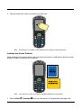
Installing Memory Cards
This terminal supports microSD and microSDHC memory cards up to 4GB.
To install an SD card, you must open the access door on the side panel (Side Panel Features, page 312). Access door removal requires a Torx 5 (T5).
1.
Press the Blue
+ Backlight
keys to put the terminal in Suspend Mode (see page 3-26).
2.
Place the terminal on a flat, secure surface with the keyboard face-down.
3.
Use a T5 screwdriver to remove the screw on the micro-SD door.
4.
Remove the access door.
5.
Slide the micro-SD card in with the contacts facing up (away from the keyboard) and the flat, straight
edge parallel to the top panel (with the imager).
Note: To remove an installed SD card while the access door is open, tap on the edge lightly to unlock
the card; the card will pop out just enough for you to grab its edge and pull it out.
!
Do NOT resume terminal operation while the access door is open! Operating the terminal
while the access door is open may cause damage not covered by the warranty.
3 - 13
6.
Replace the access door and tighten the screw. The access door must be properly sealed before
resuming terminal operation. Failure to seal the access door may cause damage not covered by the
warranty.
7.
Press the Backlight
8.
To verify that the operating system recognizes the new memory card, Tap Start > Programs > File
Explorer and navigate to the My Device\Storage Card folder. You should see the contents of the
memory card displayed on the screen.
3 - 14
key to resume operation.
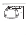
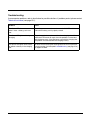
Bottom Panel Features
I/O Connector
Hand Strap Slot
Hand Strap Slot
There is an adjustable, elastic hand strap available for purchase with the terminal. When
installing the hand strap, you loop the elastic strip through this slot. For instructions, see
Attaching the Hand Strap on page 3-11.
I/O Connector
The I/O mechanical connector is designed to work exclusively with peripherals and cables
designed for the Dolphin 7600 terminal. This connector powers the terminal, charges the main
battery, and facilitates communication.
This connector supports full speed USB 1.1 communication (up to 12 Mbps) and RS-232
communications with a maximum speed of 115Kbps and seven baud rate settings.
Through this connector, you can communicate with a host workstation via Microsoft
ActiveSync; see ActiveSync Communication on page 3-18.
The I/O connector supports the following signals:
•
•
•
•
•
•
•
•
•
•
•
•
•
Data Carrier Detect
Received Data
Transmitted Data
Data Terminal Ready
Signal GND
Data Set Ready
Request To Send
Clear To Send
Ring Indicator
USB GND
USB +5V
USB D+
USB D-
Note: Signals referenced are for a DTE device.
3 - 15
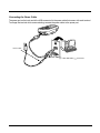
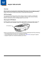
Connecting the USB Cable
Connect the USB cable to the I/O connector to facilitate USB communication between the terminal and
host workstation.
I/O
Connector
Host
Workstation
USB
Cable
*Power
Port
USB
Connector
*This is a communication-only cable until you plug the power cable into the power port.
3 - 16
Connecting the Power Cable
The power port on the back end of the USB connector fits the power cable that comes with each terminal.
To charge the terminal while communicating, connect the power cable to the power port.
Power Cable
Power Port
3 - 17
ActiveSync Communication
To synchronize, ActiveSync 4.5 or higher must be installed and configured for the appropriate
communication type on the host workstation and the Dolphin terminal. Dolphin terminals ship with
ActiveSync already installed. Therefore, if ActiveSync is already installed on the host workstation, you just
need to connect the Dolphin terminal to the host workstation (via Dolphin peripheral) to initiate
communication.
If ActiveSync 4.5 or higher is not installed on the host workstation, install it from the Getting Started CD
that came with the Dolphin terminal. Insert the CD into the CD-ROM drive of the host workstation and
follow the directions on your screen. You can also download the most current version of ActiveSync from
www.microsoft.com and install.
!
When communicating via ActiveSync, your terminal is designed to be connected to the host workstation with
a Hand Held Products communication peripheral. We recommend use of Hand Held Products peripherals,
power cables, and power adapters. Use of any non-Hand Held Products peripherals, cables, or power
adapters may cause damage not covered by the warranty.
Communication Types
The terminal supports the following types of communication via ActiveSync through its I/O Connector (see
page 3-15) on the bottom panel:
USB
The USB cable and hardware peripherals allow the terminal to communicate with a
workstation or to networked through a USB hub. The terminal supports full-speed USB
communication (USB 1.1); maximum data transfer rate is 12 Mbps. The terminal defaults
to USB communication out of the box.
RS-232
The RS-232 cable allows the terminal to communicate with a workstation, modem, or any
RS-232 device. Maximum data transfer rate is 115 Kbps.
Hardware Requirements for Setup
•
•
•
•
•
Dolphin HomeBase device
Communication cable from Honeywell
Power cable from Honeywell; see Connecting the Power Cable on page 3-17.
USB cable (for USB communication) from Honeywell
Serial cable (for RS-232 communication) from Honeywell
Software Requirements for Communication
On the workstation:
• Windows 98 Second Edition, Windows Me, Windows 2000, Windows NT (4.0, SP6 or higher), Windows
XP, or Windows Vista operating systems.
• ActiveSync must be setup on the workstation before you initiate synchronization from the terminal for
the first time.
On the terminal and the workstation:
• ActiveSync 4.5 or higher. ActiveSync must be configured for same communication type (USB or RS232) on both the host workstation and the Dolphin terminal.
Note:
3 - 18
ActiveSync software is available on the Getting Started CD that comes in the box with the Dolphin terminal.
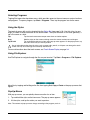
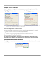
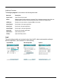
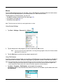
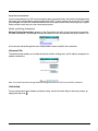
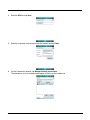
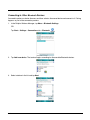
Setting Up the Host Workstation
Verify that ActiveSync is configured to use the appropriate communication type by clicking File >
Connection Settings.
For USB communication, check
Allow USB connections.
Note:
For RS-232 communication,
connect to COM1.
You can have both USB and RS-232 selected in the software without impacting processing. However, your
hardware setup should use only RS-232 or USB, not both.
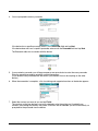
Communicating with the Dolphin Terminal
After setting up both the workstation and the terminal, ActiveSync connection should be automatic.
1.
Connect the Dolphin terminal to the a communication peripheral.
2.
The Dolphin terminal automatically opens ActiveSync to establish a connection.
Synchronizing with the Host Workstation
After setup, synchronization begins automatically whenever the terminal’s mechanical connector
connects to a Dolphin peripheral that is connected to a host workstation with ActiveSync installed.
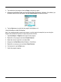
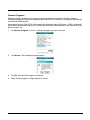
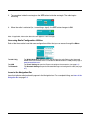
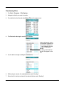
Exploring the Terminal from the Workstation
When the terminal and workstation are connected, open the main ActiveSync window (on the desktop),
and click Explore.
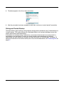
3 - 19
The Mobile Device folder opens in Windows Explorer.
The terminal is now treated as a mass storage device, and transferring files is as simple as dragging and
dropping or copying and pasting as you would for moving files between folders on your hard drive.
3 - 20
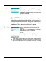
Battery Power
Dolphin terminals feature intelligent battery technology with two types of battery power:
•
•
The main battery pack on the back panel (see Main Battery Pack on page 3-21)
The backup battery located inside the terminal (see Internal Backup Battery on page 3-24)
Both batteries work together to prevent data loss when the terminal is used over long periods of time.
Both batteries must be charged to full capacity before using the terminal for the first time!
Main Battery Pack
!
We recommend use of Hand Held Products Li-Ion battery packs. Use of any non-Hand Held Products battery
may result in damage not covered by the warranty.
The Li-ion battery pack is 3.7V/3240mAh/12.0Wh and
the primary power source for both the Dolphin terminal
and the internal backup battery.
Changing the Main Battery Pack
Before installing a battery pack, press the Blue +
Backlight keys to put the terminal in Suspend Mode
(see page 3-26) so that operations are suspended
before removing the main power source. Always put the
terminal in suspend mode prior to changing the battery.
Charging Options
When the battery is installed in the terminal, you can insert the terminal into any one of the following
peripherals:
•
•
•
Power Cable (see page 2-1)
Dolphin HomeBase Device (see page 11-1)
Charge/Comm Cable (see page 3-17)
To fully charge the Li-ion battery before installing in the terminal, use the
•
Dolphin QuadCharger Device (see page 12-1)
Charging Time
The Li-ion battery pack requires four hours to charge to full capacity.
Battery Pack Storage Guidelines
To maintain optimal battery performance, follow these storage guidelines:
• Avoid storing batteries outside the specified range of -4 to 122° F (-20 to 50°C) or in extremely high
humidity.
• For prolonged storage, do not keep batteries stored in a charger that is connected to a power source.
Guidelines for Battery Pack Use and Disposal
The following are general guidelines for the safe use and disposal of batteries:
• We recommend use of Honeywell Li-Ion battery packs. Use of any non-Honeywell battery may pose a
personal hazard to the user.
3 - 21
• Replace defective batteries immediately; using a defective battery could damage the Dolphin terminal.
• Never throw a used battery in the trash. It contains heavy metals and should be recycled according to
local guidelines.
• Don’t use a battery in any other manner outside its intended use in Dolphin terminals and peripherals.
• Don’t short-circuit a battery or throw it into a fire; it can explode and cause severe personal injury.
• Excessive discharge damages a battery. Recharge the battery when your terminal indicates low battery
power.
• If you observe that the Honeywell battery supplied is physically damaged in some way, please send it
to Honeywell International Inc. or an authorized service center for inspection. Refer to the Product
Service and Repair section of this guide.
• Although your battery can be recharged many times, it will eventually be depleted. Replace it after the
battery is unable to hold an adequate charge.
• If you are not sure the battery or charger is working properly, please send it to Honeywell International
or an authorized service center for inspection.
Managing Main Battery Power
Data and files saved on the Dolphin terminal may be stored in RAM memory; therefore, maintain a
continuous power supply to the terminal to help prevent data loss. When you remove a battery pack, insert
another charged battery pack in the Dolphin. If the main battery pack is low, insert the terminal into a
charging peripheral to power the terminal and begin recharging the battery.
Note:
If the main battery is low and the terminal is in suspend mode, pressing the SCAN button does not wake
the Dolphin terminal; you must replace the discharged battery with a fully charged battery.
Default Critical and Low Battery Points
Dolphin terminals are programmed to display warnings when the battery reaches critical and low battery
points. The following registry entry sets both warning points:
[HKEY_LOCAL_MACHINE\System\CurrentControlSet\Control\Power]
There are two DWORD values in this registry entry: LowBatt and CriticalBatt. The default values for these
entries are as follows:
LowBatt=19 (25%)
This sets the Low Battery point to 25% (19 hex=25 decimal). When the battery hits the
percentage charge specified here, the user is notified by this icon in the Navigation bar .
If the main battery is low and the terminal is in suspend mode, pressing the SCAN or Power
button won’t wake the Dolphin terminal; you must replace the discharged battery with a battery
charged over 25% mark before you can resume terminal operation.
CriticalBatt=a (10%)
This sets the Critical Battery point to 10% (a hex= 0 decimal). When the battery hits the
percentage charge specified here, the user is notified by this icon in the Navigation bar .
Note:
Warnings do not appear when the terminal is on external power.
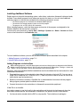
Setting Critical and Low Battery Points
Developers can re-reset the default battery points in the RegEdit Power Tool.
1. Tap Start > Power Tools > RegEdit.
3 - 22
2.
Drill-down to HKEY_LOCAL_MACHINE > System > CurrentControlSet > Control > Power.
3.
Change the Value Data of the BattPowerOff and ExtPowerOff entries.
4.
Tap OK to save changes.
Note:
These changes will not persist through a cold boot. To ensure that these settings persist through cold boots,
you need to use the RegBackup Power Tool.
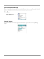
For more information about Registry Power Tools, refer to the Dolphin Power Tools User’s Guide
available for download at www.honeywell.com/aidc.
3 - 23
Internal Backup Battery
Located inside the terminal, the backup battery is a 2.4V nickel metal hydride (NiMH) battery.
The internal backup battery prevents the terminal from being reset when you remove the main battery
pack. This battery retains RAM data and allows the real-time clock to remain operational for up to 30
minutes. If the terminal is left without the main battery pack for more than 30 minutes, the internal backup
battery discharges and needs to be recharged to function according to specifications.
Note:
Even if the internal backup battery fails, data and programs stored in Flash memory (IPSM) or an optional
SD card are not lost. However, the terminal automatically cold boots when you install a fully charged battery
pack and you need to reset the real-time clock.
Charging
The internal backup battery charges off the main battery pack and requires eight hours charge time to
backup RAM data for 30 minutes. You can begin using the Dolphin terminal after charging the main
battery for four hours; however, the internal backup battery will continue to charge off the main battery.
To ensure that the internal backup battery functions properly, maintain a consistent power supply for the
first eight hours of terminal operation. This power supply can be external power (using a charging
peripheral) or an installed, charged battery pack or a combination of both.
Guidelines
Follow these guidelines to maximize the life of the Dolphin’s internal backup battery:
• Keep a charged Li-ion battery pack in the Dolphin terminal.
• Keep the Dolphin terminal connected to a power source when the terminal is not in use.
Checking Battery Power
Tap Start > Settings > System tab > Power.
3 - 24
Resetting the Terminal
There are two ways to reset the Dolphin terminal: a soft reset and a hard reset.
Soft Reset (Warm Boot)
A soft reset re-boots the terminal without losing RAM data. You would perform a soft reset 1) after
installing software applications that require a reboot, 2) after making changes to certain system settings,
or 3) when the terminal fails to respond.
1.
Press and hold Red
+ ESC
for approximately 5 seconds. The screen turns white and the
decode and scan LEDs flash for approximately three seconds.
2.
When the reset is complete, the Today Screen (see page 2-2) appears.
Hard Reset (Cold Boot)
A hard reset erases all of the data and applications stored in RAM memory and launches AutoInstall, which
re-initializes the terminal.
!
Hard resets automatically launch a soft reset as part of the boot process.
1.
Press and hold Red
+ TAB
for approximately 5 seconds. The screen turns white and the
decode and scan LEDs light for approximately three seconds.
2.
The terminal re-initializes, which re-installs all programs stored in the \IPSM\Autoinstall folder.
Note:
Set the time and date after each hard reset to ensure that the system clock is accurate. Tap the date on the
Today Screen (see page 2-2) to open the Clock setting and set the time and date.
3 - 25
Suspend Mode
Suspend mode suspends terminal operation. The terminal appears to be “off” when in suspend mode.
The terminal is programmed to go into suspend mode automatically when inactive for a specified period
of time. You can set this time period in the Power setting.
To Put the Terminal in Suspend Mode
Press the Blue
Note:
+ Backlight
keys.
You should always put the terminal in suspend mode when you change the battery pack; see Changing the
Main Battery Pack on page 3-21.
To Resume Terminal Operation
To resume terminal operation (or “wake” the terminal from suspend mode),
• Press the Blue
+ Backlight
keys.
• Press the Scan key
.
• If not in a scanning or imaging application, press one of the side buttons (see page 3-12).
Troubleshooting Suspend/Resume
If the terminal does not wake when you press the Scan key, the main battery might be too low to resume
operation. To check, remove the battery and install a fully charged battery or connect the terminal to a
Dolphin charging peripheral.
Care and Cleaning of the Dolphin Terminal
When needed, clean the image engine window and the LCD display with a clean, non-abrasive, lint-free
cloth. The terminal can be cleaned with a damp cloth.
3 - 26
4
Using the Keyboards
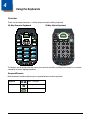
Overview
There are two keyboard options: a 29-key keyboard and the 38-key keyboard.
29-Key Numeric Keyboard
38-Key Alpha Keyboard
P2
P1
P3
P4
SCAN
SEND
END
ESC
PG
SFT
PG
F1
1
F4
4 GHI
F7
7 PQRS
TAB
F3
F2
2 ABC
3 DEF
F6
F5
5 JKL
6 MNO
F9
F8
8 TUV
9 WXYZ
F10
BKSP
0
START
SP
.
The buttons are recessed under the overlay for maximum durability and the panel is backlit for maximum
viewability in various lighting conditions.
Suspend/Resume
Both keyboards provide multiple ways to suspend/resume terminal operation.
Suspend
Blue + Backlight
Resume
Backlight
Scan
4-1
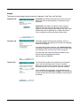
Function Keys
Function keys appear on both keyboards and perform specific functions.
Name
Key
Function
Backlight
Toggles the keyboard backlight on and off.
Backspace
Backspace moves the cursor back one space.
If you are typing text, a character is deleted each time you press the backspace key.
Escape
Cancels an action.
Enter
Performs the same function as the Enter key on a PC or workstation.
Scan
• Activates the image engine to scan a bar code or take an image.
• Wakes the terminal from suspend mode.
Tab
Moves the cursor to the next tab stop or field (on a form or application window).
The following keys appear only on the 29-key keyboard:
Shift
Provides functions as a shift key in application windows and a Caps Lock key when
the 29-key keyboard is in alpha mode.
On the 38-key keyboard, the Blue modifier key functions as a shift key in both alpha
an numeric modes.
Space
Moves the cursor one space forward.
If you are typing text, it moves the text one space forward as well.
On the 38-key keyboard, you can perform the same function as the SP key by:
• Pressing NUM + E in alpha mode
• Pressing E in numeric mode
Modifier Keys
Modifier keys modify the next key pressed to perform functions or type special characters.
Name
Blue and
Red
Key
Function
Modifies the next key pressed. The overlay of each keyboard is color-coded to
indicate the character typed or function performed when the keyboard buttons are
pressed in combination with these keys.
For modifier key combinations on the 29-key keyboard:
• See 29-Key Blue Key Combinations (Alpha Mode) on page 4-7.
• See 29-Key Red Key Combinations on page 4-8.
For modifier key combinations on the 38-key keyboard:
• See 38-Key Red Key Combinations on page 4-11.
• See 38-Key NUM Lock Mode on page 4-12.
4-2
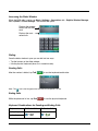
Alpha/Numeric Indicator
The Navigation bar features an icon that indicates the alpha/numeric status of the keyboard.
This icon changes when the keyboard status changes.
Icon
Keyboard Status
The keyboard is in lowercase alpha mode.
The keyboard is in shifted (uppercase) alpha mode.
The keyboard is in numeric mode.
4-3
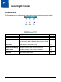
29-Key Numeric Keyboard
Hardware Application Buttons
P2
P3
P1
Escape
Navigation Keys
P4
SCAN
SEND
END
ESC
PG
SFT
PG
Scan
Enter
Shift
F1
2 ABC
F4
5 JKL
F7
6 MNO
8 TUV
9 WXYZ
F10
BKSP
0
Alpha Indicators
F9
F8
7 PQRS
3 DEF
F6
F5
4 GHI
Tab
F3
F2
1
Backspace
TAB
START
SP
Space
.
Backlight
Modifier Keys
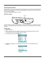
Navigation Keys
Located in the center of each keyboard for easy access with either hand, the navigation keys enable you
to move the cursor through application screens.
Key
Description
PG
Move the cursor up one row or line.
Volume up
Page up
PG
Move the cursor down one row or line.
Volume down
Page down
4-4
Move the cursor one character to the right.
+
Move the cursor one character to the left.
-
Hardware Application Buttons
These four buttons are programmed to launch software applications when the Today Screen (see page
2-2) is on the screen.
Hardware Application Buttons
P2
P1
P3
SCAN
END
P4
SEND
To customize these settings, tap Start > Settings > Personal tab > Buttons
Buttons Column
Matching Hardware Button
Buttons 1–4
Buttons P1—P4 on the 29-key keyboard.
Left
Left side button; see Side Button on page 3-12.
Right
Right side button; see Side Button on page 3-12.
.
Customizing a Hardware Button
1.
Select the button you want to modify.
2.
Select a program from the Assign a program list.
3.
Tap OK to save all changes and the change is applied immediately.
4.
To verify the change, navigate to the Today screen, press the hardware button and verify that the
selected application launches.
4-5
Toggling Between Alpha and Numeric Modes
The 29-key keyboard defaults to numeric mode, which means that the keyboard boots up to numeric
mode after each hard reset.
Numeric mode is when you type numbers with the number keys. Alpha mode is when you type letters or
characters with the number keys. The keyboard switches between alpha and numeric modes easily.
The command bar displays an icon that indicates the status of the keyboard so that you can see which
mode you’re in when toggling; see Alpha/Numeric Indicator on page 4-3.
Switching to Alpha Mode
To switch modes, tap the Blue modifier key
as follows:
• Single-tap to switch only the next character pressed to alpha mode.
The keyboard automatically switches back to numeric mode for the next key pressed.
• Double-tap to switch to alpha mode permanently.
Double-tap again to switch back to numeric mode permanently.
Alpha Indicators
Each number key has a blue section with white characters inside it that indicate which letter or symbol is
typed when you press that key in alpha mode.
Please note that when typing in alpha mode, you must use the same multi-press method you would use
when typing letters on a phone keypad. Each key press types the next letter in the sequence as displayed
by the alpha indicator.
Note: You can still use regular Blue key combinations in alpha mode by pressing and holding the Blue modifier key
with the next key in the combination. For combinations, see 29-Key Blue Key Combinations (Alpha Mode) on
page 4-7.
Shift Functionality
In Alpha Mode
When you switch the keyboard to alpha mode, letters type in lowercase by default.
To capitalize letters, tap the SFT key
as follows:
• Single-tap to capitalize only to the next letter pressed.
• Double-tap to turn CAPS LOCK on and off.
In Numeric Mode
Numeric mode is the default keyboard mode. When the keyboard is in numeric mode, tap the SFT key
once to produce special characters; see 29-Key Shift Functionality in Numeric Mode on page 4-7.
4-6
29-Key Blue Key Combinations (Alpha Mode)
Tap the Blue modifier key to switch to alpha mode for the next key pressed.
Double-tap the Blue modifier key to switch to alpha mode permanently.
Key
Character
Uppercase:
Double-tap SFT
1
@? ! :
@? ! :
2
abc
ABC
3
def
DEF
4
ghi
GHI
5
jkl
JKL
6
mno
MNO
7
pqrs
PQRS
8
tuv
TUV
9
wxyz
WXYZ
Functions
If the keyboard is in numeric mode, tap the Blue key once to achieve the following:
Key Combination
Function
Blue + Up Arrow
Volume up
Blue + Down Arrow
Volume down
29-Key Shift Functionality in Numeric Mode
When the keyboard is in numeric mode (the default state), tap the SFT key once to produce several
common characters.
Key
Character
1
!
2
@
3
#
4
$
5
%
6
^
7
&
8
*
4-7
Key
Character
9
(
0
)
29-Key Red Key Combinations
Special Characters
Key Combination
Character
Red + Left Arrow
-
Red + Right Arrow
+
Red + BKSP
*
Red + SP
#
Red + .
,
Red + P1
/
Red + P2
=
Red + P3
;
Red + P4
\
Functions
4-8
Key Combination
Function
Red + ESC (hold)
Soft reset (warm boot)
Red + TAB (hold)
Hard reset (cold boot)
Red + Up Arrow
Page up
Red + Down Arrow
Page down
Red + 1
F1
Red + 2
F2
Red + 3
F3
Red + 4
F4
Red + 5
F5
Red + 6
F6
Red + 7
F7
Red + 8
F8
Key Combination
Function
Red + 9
F9
Red + 0
F10
4-9
38-Key Alpha Keyboard
Scan
Navigation Keys
Tab
Backspace
Enter
Escape
Space
Shift
Backlight
NUM Lock Key
Modifier Keys
Toggling Between Alpha and Numeric Modes
The 38-key keyboard defaults to lowercase alpha mode, which means that the keyboard boots up to
lowercase alpha mode after each hard reset.
Numeric mode is when you type numbers with the number keys. Alpha mode is when you type letters or
characters with the number keys. The keyboard switches between alpha and numeric modes easily.
The command bar displays an icon that indicates the status of the keyboard so that you can see which
mode you’re in when toggling; see Alpha/Numeric Indicator on page 4-3.
Shift Functionality in Alpha Mode
• To apply Shift functionality to the next character pressed while in lowercase alpha mode, tap the Blue
modifier key once. Shift functionality is removed from the next key pressed automatically
• To switch into CAPS LOCK mode, tap the Blue modifier key twice.
To switch out of CAPS LOCK mode, tap the Blue modifier key twice again.
Switching to Numeric Mode
• To switch to numeric mode for the next key pressed, tap the NUM key once.
• To lock into numeric mode, double-tap the NUM key.
• If locked in numeric mode, double-tap NUM key again to switch back to alpha mode.
For more information about NUM Lock functionality, see 38-Key NUM Lock Mode on page 4-12.
4 - 10
38-Key Red Key Combinations
Key Combination
Function
Red + ESC (hold)
Soft reset (warm boot)
Red + TAB (hold)
Hard reset (cold boot)
Red + Down Arrow
P1
Red + Up Arrow
P2
Red + Left Arrow
P3
Red + Right Arrow
P4
Red + Left Side Button
P5
Red + Right Side Button
P6
Red + A
F1
Red + F
F2
Red + K
F3
Red + P
F4
Red + U
F5
Red + E
F6
Red + J
F7
Red + O
F8
Red + T
F9
Red + Z
F10
4 - 11
38-Key NUM Lock Mode
• To switch to numeric mode for the next key pressed, tap the NUM key once.
• To lock into numeric mode, double-tap the NUM key.
• If locked in numeric mode, double-tap NUM key again to switch back to alpha mode.
Numbers
Key
Character
B
1
C
2
D
3
G
4
H
5
I
6
L
7
M
8
N
9
R
0
Key
Character
J
\
Q
.
S
,
O
/
T
+
U
@
V
*
W
X
Y
#
Z
-
Special Characters
4 - 12
Special Functions
Key
Character
A
Volume up
F
Volume down
E
SP
4 - 13
4 - 14
5
Using the Image Engine
Overview
The Dolphin terminal houses a compact image engine using Adaptus™ Imaging Technology that instantly
reads all popular 1D and 2D bar codes and supports omni-directional aiming and decoding. The image
engine can also capture digital images.
*Pull the plastic tab to remove the plastic film cover over the image engine window before activating the
image engine.
Available Engines
5300 Standard Range (5300SR)
8.3 mil
Linear
*Working
Range:
(.020cm)
10 mil
PDF417
(.025cm)
13 mil
UPC
(.033cm)
15 mil
Data Matrix
(.038cm)
15 mil
QR
(.038cm)
35 mil
MaxiCode
(.089cm)
Near
3.5 in.
(8.9cm)
3.1 in.
(7.9cm)
2.1 in.
(5.3cm)
2.3 in.
5.8cm)
3.1 in.
(7.9cm)
2.0 in.
(5.1cm)
Far
7.6 in.
(19.3cm)
9 in.
(22.9cm)
13.2 in.
(33.5cm)
10.2 in.
(25.9cm)
8.8 in.
(22.4cm)
13.0 in.
(33cm)
*Data characterized at 23°C and 0 lux ambient light.
5-1
Supported Bar Code Symbologies
Symbology Type
Symbology Name
1D Symbologies
Codabar
Code 3 of 9
Code 11
Code 32 Pharmaceutical (PARAF)
Code 93
Code 128
EAN with Add-On
EAN with Extended Coupon Code
EAN-8
EAN-13
GS1-128
GS1 Databar
Interleaved 2 or 5
2D Symbologies
Aztec
Codablock
Code 16K
Code 49
Composite
Data Matrix
GS1 Databar
MaxiCode
Micro PDF
OCR
PDF417
QR Code
Composite Codes
Aztec Mesa
Codablock F
EAN·UCC
GS1 Databar-14
OCR
OCR US Money Font
MICR (E 13 B) and SEMI Font
OCR-A
OCR-B
Postal Codes
Postnet and most international 4-state codes
Australian Post
British Post
Canadian Post
China Post
Japanese Post
KIX (Netherlands) Post
Korea Post
Planet Code
5-2
ISBT 128
Matrix 2 of 5
MSI
Plessey
PosiCode
Straight 2 of 5 IATA
Straight 2 of 5 Industrial
Telepen
Trioptic Code
UPC
UPC-A
UPC-E
Activating the Engine
When a scanning application is open, press the SCAN key
to activate the image engine. You can
also press one of the side buttons (see page 3-12), which are programmed to activate the image engine
in a scanning application by default.
Using Demos
Demos are software utilities loaded on all Dolphin terminals that demonstrate the advanced features of
the terminal. There are two Demos feature the image engine: Image Demo and Scan Demo.
To access these demos, tap Start > Demos,
• Select Scan Demo to verify decoding, or
• Select Image Demo to verify imaging.
For more information about Demos, refer to the Dolphin Demos User’s Guide, which is available for
download from www.honeywellaidc.com.
LEDs
The LEDs in the center of both keyboards (for location, see LEDs on page 4-1) light when using the image
engine.
Scan LED
The LED on the right lights red when you press the scan trigger in scanning applications.
Decode LED
The LED on the left lights green when a scanned bar code is successfully decoded.
Decoding
The Dolphin terminal supports two types of image decoding: full-area imaging and Advanced Linear
Decoding (ALD).
Full-area Imaging
Full-area imaging means that the Dolphin terminal support omni-directional aiming, which
means that a positive read can be obtained from many positions. For details, see OmniDirectional Scanning Positions on page 5-4.
ALD
ALD provides fast reading of linear (1D) and stacked linear bar codes (PDF417). For the best
read, the aiming pattern should be centered horizontally across the bar code. When ALD is
enabled, the reader does not read matrix or postal codes.
To Decode a Bar Code
1.
Tap Start > Demos > Scan Demo.
2.
Position the Dolphin terminal over one of the sample bar codes on page 5-4.
A range of 4–10 inches (10–25 cm) from the bar code is recommended.
3.
Project the aiming brackets by pressing and holding the SCAN key. The Scan LED lights red.
4.
Center the aimer crosshair over the bar code. The aiming beam should be oriented in line with the
bar code to achieve optimal decoding; Omni-Directional Scanning Positions, page 5-4
5-3
5.
When the bar code is successfully decoded, the decode LED lights green and the terminal beeps.
Sample Bar Codes
You can use the following bar codes to verify decoding:
Sample 128
Sample PDF417
Code 128
PDF417 Test Message
Omni-Directional Scanning Positions
The high-vis aiming pattern frames the bar code to provide you with the best scanning performance.
Note: To achieve the best read, the aiming beam should be centered horizontally across the bar code.
The aiming pattern is smaller when the terminal is held closer to the code and larger when the terminal is
held farther from the code. Symbologies with smaller bars or elements (mil size) should be read closer to
the unit whereas larger bars or elements (mil size) should be read farther from the unit.
5-4
Capturing Images
The image-capture process is an intuitive, split-second operation for experienced users. By following
basic guidelines, however, new users can easily develop their own technique and, with practice, quickly
learn to adapt to different application environments.
Image Preview
When the imaging process is initiated, the touch screen displays a preview of the object. This
is a live video image of what the imager is currently viewing and has a slightly degraded
appearance compared to the captured image. This is normal; the captured image has a higher
resolution.
File Formats
The Dolphin terminal is capable of saving images in a number of industry-standard file formats
such as BMP, JPG and PNG. The default file format for images is a grayscale JPG.
File Size
Digital images have a maximum image size of 640 x 480 pixels and may have up to a 256
grayscale image definition. The image quality and related file size are determined by the data
compression method used by the software application used to take the image.
The average size of the image file is approximately 4–8K. However, the size of the image
depends on image content, the more complex the content, the larger the file size.
Taking an Image
1.
Tap Start > Demos > Image Demo.
2.
Point the terminal at the object.
3.
Press the SCAN key to activate the engine. The touch screen displays a preview of the object.
4.
Adjust the terminal’s position as necessary. Use the preview on the screen as a guide.
5.
Hold the terminal still and release the SCAN key.
The touch screen flashes, and the captured image appears on the screen.
6.
By default, the image is saved to the My Device folder.
To save the image to another location, tap File > Save As.
High-Vis Aiming Pattern
If your terminal is configured with the 5300SR imager, you can enable the aiming pattern for imaging in
the Image Demo application.
1. Tap Start > Demos > Imaging Demo > Options menu > Aimer.
2.
The aiming pattern is now enabled for imaging.
Uploading Images
Image files can be transmitted to a host workstation via
• Microsoft ActiveSync and a Dolphin communication peripheral
• Wireless radio: 802.11b/g and/or Bluetooth
5-5
5-6
6
System Settings
Overview
Customized settings are available on the Start menu. Tap Start > Settings and settings screen opens
displaying the Personal tab. Settings consists of three tabs: Personal, System, and Connections.
Personal Tab
System Tab
Connections Tab
Tab
Description
See Page
Personal
Customizes buttons, set SIP options, and adjust headset settings.
6-2
System
Adjusts system settings.
6-7
Connections
Establishes network connections settings.
7-1
6-1
Personal Tab
To access the Personal tab, go to Start > Settings. The screen opens displaying the Personal tab.
Icon
Description
For more information…
Buttons
Program the side buttons to perform specific tasks.
See Buttons on page 6-3.
Input
Customizes the SIP.
See Input on page 6-4.
Lock
Password protect the terminal to limit access to the terminal.
Menus
Customizes what appears on the Start menu.
Owner Information
Enter your contact information.
This information will appear on the Today screen.
Phone
When the GSM radio is enabled, tap this icon to set
up user parameters.
Sounds &
Notifications
Set the sound volume, enables and disables sounds for specific actions, and sets
sound parameters for system notifications.
Today
Customize the look and the information displayed on the Today screen.
See Menus on page 6-5.
See Setup Options on page
8-10.
Note: Personal settings are stored in RAM memory. They are replaced by system defaults after each hard reset.
For more information about resets, see Soft Reset (Warm Boot) on page 3-25.
6-2
Buttons
Buttons programs both keyboard buttons and the side buttons to launch applications or execute
commands. The default button assignments that appear on the Buttons window are inactive until you
enable the HotKeys Power Tool.
To Enable HotKeys
1.
Tap Start > Power Tools and tap the HotKeys icon once
assignments in the Buttons setting are active.
2.
Verify the assignment by tapping the button on the keyboard.
. HotKeys is enabled and the button
For more information about the HotKeys Power Tool, refer to the Dolphin Power Tools User’s Guide,
which is available for download from the web at www.honeywell.com/aidc.
Button Assignments
By default, the side buttons (for locations, see page 3-12) activate the image engine but can be
programmed to launch applications or execute commands in the Buttons setting.
1.
After HotKeys is enabled, tap Start > Settings > Personal tab > Buttons
.
Note: The buttons that appear on this window are the only buttons that can be programmed via the Buttons setting.
You cannot add buttons to this window.
2.
To change button assignment, tap on the name of the application in the Assignment column and
select a program or command in the Assign a program drop down list.
3.
Tap OK to save.
Available Applications
The Assign a program list contains the applications installed on the terminal. If there is a program
installed that you would like to see in this list, paste a Shortcut to the program in the \\Windows\Start
Menu\Programs folder. For instructions about creating shortcuts, see Using File Explorer on page 6-5.
6-3
Additional Functions
The Assign a program list also contains the following commands:
Command
Description
<Input Panel>
Opens the soft input panel.
<None>
Nothing happens when the button is pressed. This is the default setting for the LSide and
RSide buttons and means that pressing either button activates the image engine.
<OK/Close>
Performs the same function as tapping OK on the screen.
<Scroll Down>
Scrolls down in the open application.
<Scroll Left>
Scrolls left in the open application.
<Scroll Right>
Scrolls right in the open application.
<Scroll Up>
Scrolls up in the open application.
<Start Menu>
Opens the Start menu.
<Today>
Opens the Today screen.
Input
The Input settings enables you to customize input from the SIP, adjust word completion settings in
Microsoft applications, and set defaults for voice recording.
Input Method
6-4
Word Completion
Options
Menus
You can add existing programs you use often, such as File Explorer, to the Start menu for faster access.
You are not installing the program, just allowing access to it from the Start menu.
To add programs to the Start menu, you can use
• The Menus setting on the Personal tab (see page 6-5),
• File Explorer (see page 6-5), or
• ActiveSync (see page 6-6).
Note: The Start menu can hold only seven applications at a time.
Using System Settings
1.
Tap Start > Settings > Personal tab > Menus
.
2.
Tap the check box for the program you want to add and tap OK to save.
Note: If you try to go over seven applications, a warning message appears and you will have to delete
applications as necessary.
3.
Tap the Start menu to verify that the program appears on it.
Using File Explorer
If you do not see the program listed, you can either use File Explorer to move the program or ActiveSync
on the workstation to create a shortcut to the program and place the shortcut in the Start Menu folder.
Note: We recommend that you Copy and Paste Shortcut so that you do not alter your program configurations by
accident. Using Copy and Paste Shortcut (as opposed to Cut and Paste) ensures that the program files
remain where they need to be for the system to find them to perform system functions.
1.
Tap Start > Programs > File Explorer, and navigate to the program.
File Explorer opens to My Documents by default; to see a list of all folders, tap the folder name and
then My Device.
6-5
2.
Tap and hold on the program, then tap Copy on the pop-up menu.
3.
Navigate to the Windows folder and open the Start Menu (My Device > Windows > Start Menu), tap
and hold a blank area of the window, and tap Paste Shortcut on the pop-up menu.
4.
Tap the Start menu to verify that the program now appears on it.
Using ActiveSync on the Workstation
Here, you are performing the same basic process as on the terminal, except that you are using the
Explore utility (Windows Explorer) to copy and paste the shortcut.
1. Open ActiveSync > Explore and navigate to the program.
2.
Right-click on the program and select Create Shortcut.
3.
Select the shortcut, right-click, and select Cut.
4.
Navigate to the Start Menu folder (Windows > Start Menu).
5.
Right-click on an empty area and select Paste Shortcut.
6.
On the terminal, tap the Start menu.
7.
Verify that program appears.
6-6
System Tab
The System tab enables you to verify and sometimes alter system parameters. To access the System
tab, go to Start > Settings > System tab. Tap the appropriate icon to open that system setting.
For details,
• See About on page 6-7.
• See Backlight on page 6-8.
• See Certificates on page 6-8.
• See ClearType Tuner on page 6-8.
• See Clock & Alarms on page 6-9.
• See Encryption on page 6-9.
• See Error Reporting on page 6-9.
• See External GPS on page 6-10.
• See Memory on page 6-10.
• See Power on page 6-12.
• See Regional Settings on page 6-12.
• See Remove Programs on page 6-13.
• See Screen on page 6-14.
• See WAN Info on page 6-15.
About
The About system setting displays specific information about what is loaded on the terminal. It contains
three tabs:
Version Tab
Displays the information about the software, operating system, and processor of the
terminal.
Device ID Tab
Displays the information the terminal uses to identify itself to other devices. It can be
important to know this information if the Dolphin terminal is going to be part of a networked
system of devices.
Device name: Displays the system’s default name. (This is the name used by ActiveSync.)
Description: Displays the description of the device ID.
Copyrights Tab
Displays important copyright information.
6-7
Backlight
The Backlight system setting enables you to customize backlight functionality for the display. The
backlight for the color display is user-defined. Tap Start > Settings > System tab > Backlight.
There are two tabs:
The Battery tab determines display backlight settings when the terminal is running on battery power.
The External tab determines display backlight settings when the terminal is running on external power.
The options on each tab are the same.
Turn off backlight:
Select how many minutes you want to elapse before the backlight automatically turns off.
Turn on backlight:
Select this option if you want the backlight to turn on when the a button is pressed or the
touch screen is tapped.
Tap OK to save settings.
Backlight Intensity
Tap the Backlight tab and move the slider to set the intensity of the backlight. The default is 8.
Certificates
Certificates shows you which certificates are recognized by the operating system.
If the certificate does not appear on one of these tabs, then the operating system does not recognize it
and you will not be able to use that certificate.
ClearType Tuner
This system setting enables you to adjust the level ClearType font rendering by moving a slider. The
sample text displays the setting results immediately. Of course, you must first enable ClearType font
rendering to change the appearance of fonts on the screen; see ClearType Tab on page 6-14.
6-8
Clock & Alarms
This setting sets the system clock, which means that all scheduled items run according to this setting. The
time and date need to be reset after every hard reset of the terminal so that the system clock is accurate.
On the Today screen, tap the line that displays the time and date,
The Clock Settings screen appears. The selected time sets the system clock.
Encryption
Encryption gives you the option of encrypting files placed on storage cards so that those files cannot be
read by any other device.
Error Reporting
Error Reporting gives you the option of enabling or disabling the error reporting function of Windows
Mobile 6.
6-9
External GPS
If a Windows Mobile 6.0-based device is equipped with a GPS module, External GPS is a Microsoft tool
that determines which port an external GPS software application can use.
The Dolphin 7600 terminal is not equipped with a GPS module.
Memory
The Memory system setting displays capacity and usage statistics for both RAM (volatile) and IPSM/
Storage Card (non-volatile) memory. Access this setting whenever you receive system messages about
memory.
You cannot change the terminal’s memory allocation in the Memory system setting. To change the
memory allocation, you need to use the SetRAM Power Tool (Start > Power Tools > SetRAM). For more
details, please refer to the Honeywell Power Tools User’s Guide, which is available for download from
www.honeywellaidc.com.
There are three tabs: Main, Storage Card, and Running Programs.
Main Tab
This tab displays the usage statistics of the on-board,
volatile RAM memory.
Columns:
Storage=RAM memory used for storing programs and program
data.
Program=RAM memory used to run programs.
Rows:
Total= Displays the current MB of memory allocated for use.
In use=Displays the total MB of that allocated memory in use.
Free=Displays the total MB of memory available.
6 - 10
This tab displays the current capacity and usage statistics
of the selected memory type; IPSM or Storage Card.
Storage Card Tab
Select the memory type from the drop-down list. IPSM is
selected by default.
Total storage card memory=The total MB of memory capacity
of IPSM or Storage Card.
In use=The MB currently being used.
Free=The MB that is still available for use.
IPSM—Short for Internal Persistent Storage Manager, this is the on-board Flash
memory that is non-volatile. Because this memory is non-volatile, data or programs
stored in IPSM are not affected when power is removed. Autoinstall programs, for
example, are stored in IPSM so that they are always installed at cold-boot startup.
Storage Card—You can install one memory card in Dolphin terminals (see Access
Door on page 3-12). If a storage card is installed in the terminal, you can select it in
the drop-down list and see capacity and usage statistics for the card.
Running
Programs Tab
Displays the software programs currently using Storage
memory.
Check this tab when you are receiving out of memory errors or
when the mobile computer is running slowly.
You can
• Select a program in the list and tap Stop to stop it from
running (and therefore from using memory), or
• Tap Stop All to automatically stop all running programs.
!
Anytime you stop a running program, it frees up RAM memory. Be advised that, when
you stop a program here, any unsaved data in that program is lost. To free up memory
without risking data loss, return to the running program, save your data, and close the
application.
6 - 11
Power
Power system settings contains three tabs: Battery and Advanced.
Battery Tab
Displays the remaining charge of batteries.
For more information about the terminal’s batteries, see
Battery Power on page 3-21.
Advanced Tab
Determines power time-outs.
For On battery power, select from the drop-down list,
the number of minutes of inactivity you want to pass
before the terminal powers off when running on battery
power.
For On external power, select from the drop-down list,
the number of minutes of inactivity you want to pass
before the terminal powers off when running on external
power.
Note: You can also set automatic turn-off times for the terminal to conserve power. When the terminal is “turned
off,” that means it’s in suspend mode; see Suspend Mode on page 3-26.
Regional Settings
Regional Settings enables you to customize the appearance and formatting to your geographic region.
Specifically, you can customize numbers (i.e., number of decimal places allowed), currency (i.e.,using the
$ or €
€ symbol), time, and date. These specifications apply to all screens, including the Today screen. The
Region tab displays an overview of the region selected in the drop-down list at the top.
The terminal is loaded with a number of pre-programmed regional settings. Select one from the list and
the results appear on the screen.
To see specific settings or change a specific setting, tap on one of the tabs, make the change and tap OK
to save it.
6 - 12
Remove Programs
Remove Programs enables you to remove programs installed on the terminal. Use this setting to
troubleshoot when you receive messages that the terminal is out of memory. The programs removed are
removed from RAM memory.
Any program (usually CAB or DLL files) stored in the Autoinstall folder (My Device > IPSM > Autoinstall)
will re-install after the next hard reset. For information about the hard reset process, see Hard Reset (Cold
Boot) on page 3-25.
1.
Tap Remove Programs. In the list, select the program you want to remove.
2.
Tap Remove. The following message appears:
3.
Tap Yes. Wait while the program is removed.
4.
Verify that the program no longer appears in the list.
6 - 13
Screen
The Screen system setting contains three tabs: Alignment, Clear Type, and Text Size.
Alignment Tab
Orientation–The default orientation for the screen is Portrait.
Select one of the Landscape options to change the screen
orientation.
Align Screen–You need to re-align the screen if tapping
buttons or icons with the stylus no longer seems to work
appropriately. Tapping Align Screen brings up the align screen
window where you are guided to tap a target several times.
This re-calibrates how the touch screen receives input.
ClearType Tab
The display supports ClearType font rendering, which is a
Microsoft technology that dramatically increases the readability
of text on LCD displays.
To enable ClearType font rendering, select Enable ClearType
and tap OK. To adjust the level of ClearType font rendering, use
the ClearType Tuner; see ClearType Tuner on page 6-8.
For more information about ClearType font rendering, visit:
www.microsoft.com/typography/cleartype/
what.htm?fname=%20&fsize=
Text Size Tab
The Text Size tab enables you to perform font scaling within
certain views of the Today screen, Contacts, Calendar,
Messaging, and Tasks. This means that you can increase or
decrease the point size of the font on application windows.
This is the default font size setting. To change the font size,
move the slider toward Smallest or Largest. The Example text
changes to reflect the font change. Tap OK to save the new font
size setting.
6 - 14
WAN Info
When the GSM radio is active, WAN Info displays useful statistics for the radio.
To verify whether or not the GSM radio is enabled, check the Dolphin Wireless Manager (see page 7-6).
6 - 15
6 - 16
7
Connecting the Terminal
Connections Tab
The Connections system setting provides access to the terminal’s various communication options.
Icon
Description
See Page
Beam
Controls whether or not the terminal can receive data via IrDA.
7-3
Bluetooth
Configures the Bluetooth connection.
This icon appears only if a Bluetooth radio and driver is installed
on the terminal.
9-1
Connections
Opens Microsoft’s connections manager.
7-4
Dolphin Wireless Manager
Manages the wireless radios installed in the terminal.
7-6
Network Cards
Manages the network drivers installed in the terminal.
7-9
USB to PC
Offers additional USB options.
7-10
7-1
Infrared Communication
Using the IrDA port, you can send and receive data between the terminal and other devices equipped with
infrared. This can include, but is not limited to, Windows Mobile information such as Contacts and Tasks,
as well as software upgrades.
The maximum data transfer speed is 115 Kbps.
IrDA Port Location
IrDA Port
To send or receive, the IrDA ports of both devices - whether it’s two terminals, or a terminal and a host
device - must be aligned with each other and within a close range. The maximum data-transfer speed is
115 Kbps.
Sending Data
1.
Align the IrDA ports.
2.
Open the program where you created the item you want to send and locate the item in the list.
You can also beam files, but not folders, from File Explorer.
3.
Tap and hold the item and select Beam File.
4.
The IrDA port searching for a receiving IrDA port in the vicinity. The selected device reads
“Pending.”
7-2
5.
When the IrDA port finds the IrDA port of the other device, it immediately starts sending the selected
file. The selected device reads “Sending.”
6.
When the file transfer is complete, the selected device reads “Done.”
Receiving Data
The Beam Setting must be set to receive for the terminal to receive data from other infrared devices.
1. Verify that beam settings are set to receive. Tap Start > Settings > Connections tab > Beam. The
Beam Settings window should appear as follows:
2.
Align the IrDA ports.
3.
Have the owner of the other device send the information to you.
4.
Your terminal automatically begins receiving it.
5.
A popup message appears asking if you want to receive the incoming file.
6.
Tap Yes to receive the file.
7-3
Connections Manager
The connections manager sets up various network connections to Internet Service Providers (ISPs) via
external modem.
To open the connections manager, tap Start > Settings > Connections tab > Connections icon
.
Server-Assigned IP Addresses
All server-assigned IP addresses use Dynamic Host Configuration Protocol (DHCP).
Zero-Config Wi-Fi
The zero-config Wi-Fi feature of Windows Mobile is disabled on Dolphin 7600 terminals.
If you are using one of the on-board wireless radios to connect to a network, do not enter
network parameters in the connections manager. The Dolphin terminal uses the radio’s
settings to connect to the network.
Task Tab
The Task tab enables you to initially configure, then manage network settings when using a modem.
Select an item in this list and then complete the setup screens that follow with the appropriate information
for your network.
My ISP
The links under this heading enables you to add and manage modem connections to an ISP. To complete
the setup screens, obtain the following information from your ISP:
•
•
•
•
ISP dial-up access telephone number
Username
Password
TCP/IP settings
My Work Network
These links enable you to establish the following connections types:
•
•
•
Modem
Virtual Private Network (VPN)
Proxy server connection
To complete the setup screens, obtain the network parameters from your system administrator.
7-4
Proxy Server Connections
If you are connected to your ISP or private network during synchronization, the terminal should download
the proper proxy settings during synchronization with the PC. If these settings are not on your PC or need
to be changed, ask your ISP or network administrator for the proxy sever name, server type, port, type of
Socks protocol used, and your user name and password.
Modify an Existing Connection
Manage Existing Connections appears on the Connections tab after at least one network connection
has been established. Tap Manage Existing Connections on this tab and follow the setup screens. You
will usually be walked through the same setup screens used to establish the connection.
Advanced Tab
The Advanced tab enables you to select the default network, dialing rules, and IP address exceptions for
modem connections.
Note: You should not need to change Advanced settings because most ISPs now use DHCP addresses.
Online Help
For more information about modem connection setup, consult the online help on the setup screens by
tapping the Help icon .
7-5
Dolphin Wireless Manager
The Dolphin Wireless Manager provides a centralized interface that enables and disables all the on-board
radios. Each radio has its own configuration program and the Dolphin Wireless Manager also provides
shortcuts to the configuration utilities for each radio.
There are three radio options: 802.11b/g, GSM/GPRS, and Bluetooth.
1. 802.11b/g
The WLAN radio is configured in the Honeywell WLAN Secure Wireless Client (SWC).
Refer to the Honeywell WLAN SWC User’s Guide, which is available for download from the
7600 product page at www.honeywellaidc.com.
2. GSM/GPRS
See Working with GSM on page 8-1.
3. Bluetooth
See Working with the Bluetooth Radio on page 9-1.
Dolphin Wireless Manager Window
Tap Start > Settings > Connections tab > Dolphin Wireless Manager
Each rectangle represents a radio.
.
If a rectangle is grayed-out,
then the radio is not installed
on the terminal.
These buttons show you the
state of the radio.
If applicable, information about
the radio appears when the
radio is activated.
Enabling the Radios
1.
7-6
Tap Start > Settings > Connections tab > Dolphin Wireless Manager
.
2.
Tap anywhere inside the rectangle or the OFF button inside the rectangle. The radio begins
activating.
3.
When the radio is activated (i.e., transmitting a signal), the OFF button changes to ON.
Note: If applicable, information about the radio appears in the rectangle.
Accessing Radio Configuration Utilities
Each of the three radios have their own configuration utilities that you can access through the Menu.
For 802.11b/g
Tap WLAN Settings to open the SWC and configure the radio. Refer to the Honeywell
WLAN SWC User’s Guide, which is available for download from the 7600 product page at
www.honeywellaidc.com.
For GSM
Tap Phone Settings to open the Phone and configure the connection (see page 8-1).
For Bluetooth
Tap Bluetooth Settings to open the Bluetooth Manager and configure the radio (see page
9-1).
Icons in the Navigation Bar
Icons that indicate radio functionality appear in the Navigation bar. For a complete listing, see Icons in the
Navigation Bar on page 2-3.
7-7
COM Port Assignment Table
7600 with Windows Mobile Professional (with GSM):
COM Port
Description
COM0
Unused
COM1
Not accessible
COM2
Serial Port: RS-232 Connector on the bottom panel
COM3
Not accessible
COM4
IrDA: Serial Infrared (SIR) up to 115 Kbps
COM5
USB Serial: Virtual USB Serial port for ActiveSync
COM6
Not accessible
COM7
Not accessible
COM8
BT Serial: Bluetooth serial interface
COM9
Not accessible
7600 with Windows Mobile Classic (without GSM):
COM Port
Description
COM0
Unused
COM1
Serial Port: RS-232 Connector on the bottom panel
COM2
Not accessible
COM3
IrDA: Serial Infrared (SIR) up to 115 Kbps
COM4
Not accessible
COM5
Bluetooth DUN
COM6
IrCOMM
COM7
Unused
COM8
USB Serial: Virtual USB Serial port for ActiveSync
COM9
Bluetooth BTHATCI server
7-8
Network Cards
The Network Cards setting displays the network cards installed in the terminal.
1. Tap Start > Settings > Connections > Network Cards.
2.
Tap on an adapter in the list to review its settings. (Server-assigned IP addresses use DHCP.)
3.
If you make a change on one of these tabs, tap OK to confirm the changes.
4.
You must perform a soft reset to update the registry entries; see Soft Reset (Warm Boot) on page 325. During the soft reset, the new registry entries are created and can be read by the applications
that need them.
!
Do NOT perform a Hard Reset (Cold Boot) (see page 3-25) after modifying an adapter here. Hard resets return
the terminal to factory defaults, which erases network adapter modifications made here.
7-9
USB to PC
The USB to PC applet enables you to switch between RNDIS (Remote Network Driver Interface
Specification) USB and Serial USB communication.
Dolphin 7600 terminals default to Serial USB. Honeywell recommends using Serial USB.
To change this setting, tap Start > Settings > Connections tab > USB to PC
is not selected, which indicates Serial USB.
. The enable option
To switch to RNDIS USB, select Enable advanced network functionality and tap OK to save. (Wait as
the terminal makes the change.)
7 - 10
Installing Additional Software
Dolphin terminals ship with the operating system, radio drivers, and custom Honeywell software already
installed. These default programs install when your terminal first boots up. You can install additional
software programs to the terminal provided that the following parameters are met:
•
•
•
The software program was created for the Windows Mobile platform.
The terminal has enough memory to store and run the program.
The program has an EXE, CAB, or DLL extension.
When selecting programs, verify that the program and version of the program are designed for the
Windows Mobile 6 and the terminal’s processor.
You can verify your processor by tapping Start > Settings > System tab > About > Version tab. Make
a note of the information in the Processor field.
To install additional software, you can use the communication options described in this chapter.
• Adding Programs via ActiveSync, page 7-11.
• Infrared Communication, page 7-2.
Adding Programs via ActiveSync
!
When selecting programs, verify that the program and version of the program are designed for the Windows
Mobile 6 and the terminal’s processor. You can verify your processor by tapping Start > Settings > System tab
> About > Version tab. Make a note of the information in the Processor field.
Generally, software for Windows Mobile-based devices must be installed to the host workstation first, then
transferred to the terminal.
1. Download the program to the workstation from either the Internet or the install CD. You may see a
single EXE or setup.exe file, a CAB file, or DLL. (There may also be several versions of files for different device types and processors.)
2.
Read any installation instructions, Read Me files, or documentation that comes with the program.
Many programs provide special installation instructions.
3.
Connect the terminal to the workstation via Honeywell communication peripheral.
If the File is an Installer
An installer program is one that installs to the workstation and the terminal simultaneously when the
workstation and the terminal are connected via ActiveSync; one process installs to both devices.
1. On the workstation, double-click the EXE or setup.exe file. The installation wizard begins.
7 - 11
2.
Follow the directions on the workstation screen.
The installation process includes transferring the software to the terminal via ActiveSync.
If the File is Not an Installer
Some programs cannot be installed on workstations because they are designed exclusively for Windows
Mobile-based devices. In these cases, the appropriate files must be stored on the host workstation and
transferred to the terminal via ActiveSync Explore.
Note: You know that the program is not an installer because an error message stating that the program is valid but
designed for a different type of computer appears when you try to install the program on the workstation.
1.
If you cannot find any installation instructions for the program in the Read Me file or documentation,
open ActiveSync on the workstation and click Explore.
2.
On the workstation, navigate to the workstation folder containing the program file(s) and copy them
to the Program Files folder on the terminal.
If you want the program to persist through hard resets, past the program to the Autoinstall folder
(\IPSM\AutoInstall).
3.
On the terminal, tap Start > Programs > File Explorer and navigate to the folder where the
program is located.
4.
Double-tap on the program file to install it.
If you copied the file to the Autoinstall folder, you can choose to install the program by performing a
hard reset. The program installs as part of initialization.
5.
After installation is complete, access the program by tapping Start > Programs and the program
appears on the Programs screen.
6.
Tap the icon to open the program.
Adding Programs From the Internet
When you have established a network connection (whether via modem or wireless radio), you can access
the Internet and download additional software programs.
When selecting programs, verify that the program and version of the program are designed for Windows
Mobile 6 and the terminal’s processor. You can verify your processor by tapping Start > Settings > System tab
> About > Version tab. Make a note of the information in the Processor field.
!
1.
Open Internet Explorer and navigate to the program’s location. You may see a single EXE or
setup.exe file, or several versions of files for different device types and processors.
2.
Select the program version that matches your Dolphin terminal and processor.
3.
Read any installation instructions, Read Me files, or documentation that comes with the program.
Many programs provide special installation instructions.
4.
Download the program to the terminal straight from the Internet.
You would normally store the program in the \Program Files folder unless another location is
required by the program.
5.
On the terminal, double-tap the installer file; e.g., the EXE file.
6.
The installation wizard for the program begins.
7.
Follow the directions on the screen to complete installation.
7 - 12
8
Working with GSM
Overview
The Dolphin 7600 can be configured with an integrated, embedded GSM/GPRS EDGE quad-band radio
module for WWAN communication.
GSM
Short for Global System for Mobile communications, GSM is an open, non-proprietary wireless
WAN system that is constantly evolving and growing.
GPRS
Short for General Packet Radio Service, GPRS is a non-voice value added service that allows
packet-switched data to be instantly sent and received across mobile telephone networks.
Requirements
Using GSM/GPRS requires a:
• Network subscription to a GSM/GPRS network (you need to know what service providers are in your
geographic area), and
• An installed SIM card that has been activated by the network service provider (see SIM Card
Installation on page 8-2).
Antenna
Dolphin terminals configured with a GSM radio feature an internal antenna that is optimized for power
output and receiver sensitivity. This is an omni-directional antenna with zero dBm gain.
There are two different antennas based on geographical location; each supports two bandwidths:
Europe:
Supports 900 MHz and 1800 MHz bands.
North America: Supports 850 MHz and 1900 MHz bands.
Signal Strength
The signal strength of the GSM connection is indicated by the number of bars that appear in the signal
strength icon in the Navigation bar at the top of the window.
Icon
Indicates…
The signal strength of the radio connection.
The signal strength of the data connection; see page 8-5.
The signal strength of the phone (voice) connection; see page 8-8.
8-1
Voice and Data Communication
Dolphin terminals with integrated GSM/GPRS radios are optimized for the following two-way voice and
data communications:
Voice:
GSM voice data ("dial-up")
Data:
GPRS Class 12: Data transmissions average 40-60 Kbps (available speed depends on the
wireless network carrier).
You can use the GSM radio for voice communication and data communication but not at the same time.
If you want to communicate over the phone (voice), you cannot send data. If you want to send data, you
cannot use the phone.
Icons in the Navigation Bar
Icons that indicate radio functionality appear in the Navigation bar. For a complete listing, see Icons in the
Navigation Bar on page 2-3.
SIM Card Installation
Short for Subscriber Information Module, a SIM card stores the subscriber's personal information, GSM/
GPRS radio settings, security keys, contacts, etc. SIM cards are installed in compatible mobile devices,
which enables users to switch devices without losing personal and setup information.
SIM Card Requirements
• The SIM card must be activated by the service provider.
• The terminal must be powered down.
Note: If no SIM card is installed, you can still make emergency phone calls such as 9-1-1, for example.
To Install a SIM Card
On the 7600, the SIM card slot is located under the SIM card door, which is under the battery well on the
back panel. This location enables easy access to the SIM card while securing it under an installed battery.
You must use a Torx 5 (T5 x 50) screwdriver to open the SIM card door.
1.
Tap Blue + Backlight to put the terminal in Suspend mode.
2.
Lay the terminal keyboard facing down.
3.
Remove the main battery.
4.
Using a Torx 5 screwdriver, unscrew the SIM card door and set it aside.
5.
Slide the metal door down towards the I/O connector to unlock it. (Refer to the guiding arrows for
assistance.)
6.
Lift the metal door.
8-2
7.
Place the SIM card in the base of the connector with the contacts facing down so that those contacts
connect with the SIM card interface.
Guiding Arrows
SIM Card
SIM Card Door
Metal Door
SIM Card Interface
8.
Fold the metal door down and slide the door up to lock the SIM card in place. You will hear a click
when the door is locked.
Note: You will not be able to close the SIM card door unless the SIM card is locked in place.
9.
Fasten the SIM card door.
10. Insert the battery pack and tap the SCAN key to wake the terminal from Suspend mode.
11. When the operating system recognizes the new SIM card, a notification message pops up.
8-3
Enabling the GSM Radio
Be default, the GSM radio should be enabled after each Hard Reset (Cold Boot) (see page 3-25). Verify
the status of the radio in the Dolphin Wireless Manager.
1.
Tap Start > Settings > Connections tab > Dolphin Wireless Manager
2.
Tap anywhere inside the Phone rectangle and Phone begins activating.
3.
When the radio is activated (i.e., transmitting a signal), the OFF button changes to ON and the
Phone section displays additional information about the GSM radio.
8-4
.
Data Communication
You set up data communication via the connections manager. The carrier on the SIM card is the ISP.
System Requirements
• The GSM radio must be enabled; see Enabling the GSM Radio on page 8-4.
• You must have an active SIM card installed; see SIM Card Installation on page 8-2.
• The Phone must not be in use. The
but the phone is not in use.
in the Navigation bar indicates that the GSM phone is active
Information Requirements
You must have from the SIM card carrier:
• The APN (Access Point Name) number.
• The username and password of the account.
Establishing Data Communication
1.
Tap Start > Settings > Connection tab > Connections
.
2.
Under My ISP, tap Add a new modem connection.
3.
Enter a name for the connection, select Cellular Line (GPRS) as the modem, and tap Next.
8-5
4.
Enter the APN and tap Next.
5.
Enter the username and password from the account and tap Finish.
6.
On the Connections window, tap Manage existing connections.
The connection you just created should appear in the list on the modem tab.
8-6
7.
Tap and hold on the connection and select Connect on the popup menu.
8.
The network icon in the Navigation bar indicates the GSM radio is attempting to connect
9.
When the connection is complete, the network icon changes to:
.
.
10. You can now send data over GSM.
Ending the Data Connection
You need to end the data connection to use the phone. By default, the data connection will disconnect
after a certain amount of time passes without use. This period of time is determined by ISP.
To end the data connection manually, tap the network icon in the Navigation bar
Disconnect on the popup bubble.
and select
8-7
Voice Communication
You can use the Dolphin terminal as a phone via the GSM radio.
Audio Modes
There are two audio modes: Speakerphone and Headset.
Speakerphone
Use the microphone on the front panel and the speaker on the back panel to operate the GSM
phone in Speakerphone mode. Speakerphone is the default audio mode.
Headset
Headset mode is when you use a headset with earplug for audio input and the microphone for
audio output.
You can use two kinds of headsets: a mechanical headset or a Bluetooth headset.
For mechanical headsets, you must use a 2.5mm plug; no other audio plug will fit in the audio
jack on the side panel; see Headset Jack on page 3-12. The terminal switches from
speakerphone to headset mode automatically upon the insertion of the plug and returns to
speakerphone when the plug is removed.
For a Bluetooth headset, you need to activate the Bluetooth radio on the terminal and connect
to the Bluetooth headset; for more information, see Connecting to Bluetooth Headsets on page
9-6. The terminal switches from speakerphone to headset automatically when the Bluetooth
headset is connected and returns to hands-free mode when the Bluetooth headset is
disconnected.
Volume Control
Use the Dolphin keyboard to manually adjust the volume in all audio modes.
PG
To raise the volume, press the Blue modifier key + up arrow.
+
PG
8-8
To lower the volume, press the Blue modifier key + down arrow.
Accessing the Dialer Window
When the GSM radio is active, tap Start > Settings > Connections tab > Dolphin Wireless Manager,
then tap Menu > Phone Settings. The Phone dialer opens.
Displays the network
carrier from the SIM
card.
Displays the most
recent calls.
Dialing
Once the dialer window is open you can dial out two ways:
• Tap the buttons on the dialer window.
• Use the physical keyboard (when it’s in numeric mode).
Sending Calls
After the number is dialed, tap Talk
Note: The
or use the keyboard combination.
icon in the Navigation bar indicates that the phone is in use.
Ending Calls
While the phone call is live, tap End
or use the physical keyboard.
Keyboard Combinations for Sending and Ending Calls
Keyboard
29-Key Keyboard
To End a Call
+
To Send a Call
+
38-Key Keyboard
8-9
Setup Options
On the Dialer window, tap Menu > Options.
You can also tap Start > Settings > Personal tab > Phone
when the GSM radio is enabled.
The Phone Settings tab windows appear.
Phone Tab
Services Tab
This tab displays the phone number
as well as the available sounds and
security options.
This tab displays the available
options from the carrier on the SIM
card.
You can secure your phone with a
PIN.
When you tap Get Settings, the
GSM radio queries the network.
8 - 10
Network Tab
This tab allows you to choose
certain network options, including
roaming.
Tap Find Network to find available
networks in range of the phone.
Roaming
You can select automatic or manual roaming. The Phone defaults to automatic roaming.
1.
When an active SIM card is inserted in the terminal, tap Start > Settings > Personal tab > Phone
. The Phone Settings window appears.
2.
Select the Network tab.
3.
Under Network selection, select Automatic (the default selection) or Manual.
a. If you select Manual, the Phone searches for available networks.
b. The found networks appear.
c. Select a new network and tap OK. The Phone registers on the new network and the Network tabs
appears.
d. To switch to another network, tap the now active Select button and the process repeats.
4.
To switch back to automatic roaming, select Automatic under Select networks and tap OK.
8 - 11
8 - 12
9
Working with the Bluetooth Radio
Enabling the Bluetooth Radio
You enable the Bluetooth radio in the Dolphin Wireless Manager (see page 7-6).
1.
Tap Start > Settings > Connections tab > Dolphin Wireless Manager
.
2.
Tap anywhere inside the Bluetooth rectangle and Bluetooth begins activating.
3.
When the radio is activated (i.e., transmitting a signal), the OFF button changes to ON.
Now, the Bluetooth radio is transmitting a signal. Additional text in the Bluetooth section tells information
about the Bluetooth radio. “Visible” and “Not visible” indicates whether the Bluetooth radio is discoverable
or not discoverable by other Bluetooth devices.
Now, you can connect to other transmitting and discoverable Bluetooth devices (see page 9-2).
To make the terminal discoverable for other Bluetooth devices to find, you need to make the Bluetooth
radio discoverable (see page 9-8).
Icons in the Navigation Bar
Icons that indicate radio functionality appear in the Navigation bar. For a complete listing, see Icons in the
Navigation Bar on page 2-3.
9-1
Connecting to Other Bluetooth Devices
You need to perform a device discovery and then select a discovered device and connect to it. Pairing
happens as part of the connection process.
1. In the Dolphin Wireless Manager, tap Menu > Bluetooth Settings.
OR
Tap Start > Settings > Connections tab > Bluetooth
.
2.
Tap Add new device. The terminal begins searching for discoverable Bluetooth devices.
3.
Select a device in the list and tap Next.
9-2
4.
You are prompted to enter a passcode.
If the device has a specific passcode, enter it in the Passcode field and tap Next.
If the device does not have a specific passcode, enter one in the Passcode field and tap Next.
The Bluetooth radio tries to connect with the device.
5.
If you created a passcode, you will be prompted by the other device to enter the same passcode.
Enter the created passcode to establish a paired connection.
(If you entered a the passcode from the device, you shouldn’t have to do anything on the other
device.)
6.
When the connection is complete, a list of matching and supported services on the device appears.
7.
Select the services you want to use and tap Finish.
The services on the new devices have to be selected or else the pairing won’t include those
services, even though the devices are paired. If services are not selected, you will be continually reprompted for the passcode from the device.
9-3
8.
The device appears in the list on the main window.
9.
After the passcodes have been accepted on both sides, you have a trusted (“paired”) connection.
Pairing and Trusted Devices
The terminal does support pairing. Pairing happens during general connection setup. Paired devices are
"trusted" devices. This means that there is unrestricted access to all services (including services that
require authorization and authentication).
A connection can exclude pairing. A device that is connected to the terminal but not paired with it is
considered an untrusted device. Content can still be passed to untrusted devices by requiring
authorization with each attempt (for example, with the initialization of a file exchange). The Beam File
method of file transfer on the can be used to pass a file as an untrusted device; see Transferring Files on
page 9-7.
9-4
Types of Devices and Services
When you tap Add new device on the Devices tab, the Bluetooth radio scans for discoverable Bluetooth
devices in range, which are Bluetooth devices that have been made discoverable.
Device Types
The types of devices in the vicinity of
the radio appear in the list of
discovered devices.
Supported Services
Only the services that are mutually supported on both devices appear on the Partnership Settings
window.
9-5
Connecting to Bluetooth Printers
1.
Make sure the Bluetooth printer is in range and set to be discoverable by other Bluetooth devices.
2.
Look up the Bluetooth printer’s broadcasted ID.
3.
Perform a device discovery (Tap Settings > Connections > Bluetooth > Add new device.)
4.
Look for the Bluetooth printer’s broadcasted ID in the list of discovered devices.
5.
Click on the Bluetooth printer’s ID and wait for the prompt to enter a Passcode.
6.
If required, enter the Passcode and tap Next.
The passcode may default to either “1111” or “0000.” If there is no default, consult the printer
literature for the number.
7.
Select a printing-related service in the list of services.
8.
Tap Finish to establish the connection on the terminal.
9.
Complete any additional steps required by the printer.
Connecting to Bluetooth Headsets
1.
Make sure the Bluetooth headset is in range and set to be discoverable by other Bluetooth devices.
2.
Look up the headset’s broadcasted ID.
3.
Perform a device discovery (Tap Settings > Connections > Bluetooth > Add new device.)
4.
Look for the headset’s broadcasted ID in the list of discovered devices.
5.
Click on the headset’s ID and wait for prompt to enter a passcode.
6.
If required, enter the Passcode and tap Next.
The passcode may default to either “1111” or “0000.” If there is no default, consult the printer
literature for the number.
7.
Select Headset in the list of services.
8.
Tap Finish to establish the connection on the terminal.
9.
Complete any additional steps required by the headset.
9-6
Transferring Files
1.
Tap Start > Programs > File Explorer.
2.
Navigate to the file you want to transfer.
3.
Tap and hold on the file and select Beam File on the popup menu.
4.
The Bluetooth radio begins searching for devices.
When a Bluetooth device
is first found, it appears as
an Unknown device; the
icon indicates that the
device is a Bluetooth
device.
As data is retrieved, the
device IDs appear in the
list.
5.
Tap the device to begin sending the selected file.
6.
While trying to connect, the selected device reads “Pending.”
7.
When the file is being transferred, the selected device reads “Sending.”
9-7
Making the Terminal Discoverable
By default, the Dolphin terminal is not discoverable, which means that the terminal will not be found by
other Bluetooth devices.
To make the terminal discoverable, tap the Mode tab on the Bluetooth Settings window.
Select Make this device visible to other devices and tap OK.
9-8
10
Dolphin 7600 with GPS
Overview
GPS functionality can be integrated into certain Dolphin 7600 terminals. There’s no need to carry multiple
devices to get the job done because the 7600 integrates into one device powerful mobile computing,
wireless full-area voice and data communications, and advanced GPS functionality.
GPS Functionality
The integrated GPS technology allows location tracking of workers and vehicles, providing better
utilization of field assets. Optional mapping and navigation software provides turn-by-turn driving
directions and location information, allowing workers to arrive on time.
Powering the GPS Module
The GPS module is powered by the I/O Connector, which contains a pin that can power out at 5 volts
(5V). In general, this pin is disabled; however, on 7600s with GPS, this pin powers out by default.
I/O Connector
However, even when the pin is set to power out, the I/O Connector will not power the GPS module during:
• The cold boot process. 5V power out is restored after AutoInstall.
• The warm boot process. 5V power out is restored after the Today Screen (see page 2-2) appears.
• Suspend. 5V power out is restored immediately upon resume.
10 - 1
Suspend/Resume with GPS
When the terminal goes into suspend mode, power is removed from the GPS module. There are two ways
to control the Suspend/Resume activity of the terminal: via the keyboard or via activity timeout.
Suspend Via Keyboard Combination
Press Blue + Backlight keys.
Suspend Via Activity timeout
Dolphin terminals suspend when the device is inactive for a programmed period of time. This period of
time is set in the Settings -> System -> Power applet; see Power on page 6-12.
A GPS application can prevent this suspend by calls to SystemIdleTimerReset(). For example, to
determine the frequency with which to call SystemIdleTimerReset() in a battery powered situation,
retrieve the following registry value:
HKEY_LOCAL_MACHINE\SYSTEM\CurrentControlSet\Control\Power\Timeouts\BattSuspendTimeout
This value corresponds to the value set in the Power Applet discussed on page 6-12. For example, if this
value is set to 120 (seconds), an inactive system running on battery power will suspend in 120 seconds
unless a running application calls SystemIdleTimerReset() within the 120 second timeout period.
This function must be used appropriately! Keep in mind that a program that never suspends (or
! sleeps) by continually calling SystemIdleTimerReset() quickly drains the battery.
Note: For complete instructions about Suspend/Resume in general, see Resetting the Terminal on page 3-25.
Time to First Fix (TTFF)
The duration of time spent in suspend mode affects the time it takes to acquire a positional fix when the
terminal resumes normal operations. This is known as “Time To First Fix” (TTFF).
Note: When the terminal boots up for the first time from the factory, TTFF can take up to 15 minutes.
Typical TTFF From No Satellite Data
The terminal stops acquiring GPS data when
1. The terminal goes into suspend mode, which can happen manually or due to device inactivity.
GPS data acquisition begins again when the terminal resumes normal operation. You have to wake
the terminal manually by pressing the Scan key. For more information, see Resetting the Terminal
on page 3-25.
2.
The terminal moves to a location where it cannot receive satellite signals; inside a building that
blocks satellite reception, for example.
Typical TTFF
Type of Start
Start Description
Typical TTFF
Cold Start
No satellite data has been received for 16 hours
40 seconds
Warm Start
No satellite data has been received for 30 minutes
25 seconds
Hot Start
No satellite data has been received for 15 minutes
1 seconds
10 - 2
Serial Communications
The GPS module sends data to serial COM port 2 of the terminal. The default data rate is 57600 bps,
which is non-configurable.
Because data from the GPS module is sent to the 7600 via the I/O connector, serial ActiveSync and other
external serial RS-232 device input connections are not possible. However, USB ActiveSync is available
at all times.
GPS Demo
The 7600 contains a GPS application that demonstrates the main functionality of the integrated GPS
module. To use the GPS Demo, tap Start > Demos > GPS Demo.
For complete information about how to operate the GPS Demo, refer to the Demos User’s Guide for
Windows Mobile 6, which is available for download from www.honeywellaidc.com.
10 - 3
10 - 4
11
Dolphin HomeBase Device
Overview
The Dolphin HomeBase device is a charging and communication cradle that supports full-speed USB 1.1
communication with a workstation. You can also purchase a serial RS-232 version of this base.
Battery Charging
A full charge of the main battery pack takes less than four hours.
The intelligent battery charging system in the terminal that protects the battery from being damaged by
overcharging. The terminal senses when a battery pack is fully charged and automatically switches to a
trickle charge that maintains the battery at full capacity.
As a result, terminals may be stored in the base indefinitely without damage to the terminals, battery
packs, or peripherals.
Communication
The base can communicate via USB or serial RS-232. Data transmission for USB is up to 12 Mbps. Data
transmission for serial RS-232 is up to 115 Kbps.
These bases cannot be physically connected to each other–sometimes referred to as “daisy-chaining”–
but can be networked together via serial or USB hubs.
Convenient Storage
The battery charging system makes the base a safe and convenient storage receptacle for your terminal.
Capacity
The base holds one terminal and charges its battery pack.
Power Supply
The power cable that ships with each unit also powers the base.
!
We recommend use of Hand Held Products peripherals, power cables, and power adapters. Use of any nonHand Held Products peripherals, cables, or power adapters may cause damage not covered by the warranty.
!
We recommend use of Hand Held Products Li-Ion battery packs. Use of any non-Hand Held Products battery
may result in damage not covered by the warranty.
11 - 1
Front Panel
Terminal Well
Dock LED
Terminal Well
Place the terminal in this well to communicate with a host device, power the terminal, and
charge its battery.
Dock LED
Turns solid green when the terminal is properly seated in a powered base. When this light is
on, the terminal is connected to the base.
Rubber Feet
The bottom panel has four rubber feet–one at each corner–to stabilize the unit on a flat
surface. You can set the base on a dry, stable surface, such as a desktop or workbench near
an electrical outlet.
11 - 2
Back Panel
DC Power Jack
Pivot Connector
USB Port
Pivot Connector
This pivoting connector swivels 90 degrees. The default position is horizontal, with the
connectors facing straight out the back panel. The pivot connector stops in both the horizontal
and vertical positions, with the connectors facing out the bottom panel.
DC Power Jack
Connect the power cable to this power jack; see Power on page 11-4.
USB Port
This USB port is full-speed (v1.1). Using the USB cable, you can connect the base to a USBcompliant device to facilitate USB communication to and from the terminal. USB
communication occurs through Microsoft ActiveSync (v.4.5 or higher). For more information
about ActiveSync setup, see ActiveSync Communication on page 3-18.
Note: You can also purchase a serial version of the base with a standard DB9 connector for RS-232
communication.
11 - 3
Power
The terminal requires 5 volts DC input for communication and battery charging; the power adapter on the
power cable converts the voltage from the power source to 5 volts DC. Only power adapter cables from
Hand Held Products convert the voltage appropriately.
The same power cable that ships with each terminal can be used to power the base. This cable contains
a plug adapter for each geography (US, UK, EU, etc.).
1
Plug Adapter
Power Adapter
Power Cable
1.
Attach the appropriate plug adapter to the power adapter.
2.
Plug the power cable into the power source.
3.
Plug the connector into the DC power jack on the back panel. The base is now powered.
When a terminal is properly seated in the terminal well, the base powers the terminal, charges the
terminal’s main battery pack, and launches ActiveSync (see ActiveSync Communication on page 3-18).
Honeywell recommends that you leave the base connected to its power source at all times, so that it is
always ready to use.
11 - 4
Charging the Main Battery
Battery packs achieve a full charge in less than four hours.
As battery packs charge, the charging circuitry follows the two-step
charging process (CC-CV) that is recommended for Li-Ion batteries.
The process monitors changes in temperature, current, and voltage.
Inserting a Terminal
1.
Install the battery pack in the terminal; see Install the Main Battery
on page 2-1.
2.
Power the base; see Power on page 11-4.
3.
Slide the terminal into the terminal well until the Dock LED lights
green to indicate that the terminal is properly seated.
4.
The battery pack begins charging.
Checking Battery Power
To check battery power while the terminal is operating,
tap Start > Settings > System tab > Power
.
11 - 5
Mounting
If you want to mount to a vertical surface, be sure to provide enough workspace with good lighting for the
user to view and operate the Dolphin terminal while it is seated in the base.
Back Panel Dimensions
.15 in.
(3.85 mm.)
.32 in.
8.06mm Diameter,
2 places
1.44 in.
(36.7 mm.)
.53 in.
13.65mm,
2 places
3.99 in.
(101.42 mm.)
1.85 in.
(46.87 mm.)
4.35 in.
(110.47 mm.)
Mounting Guidelines
1.
Before you begin, make sure you have two screws that are size #4–diameter measurement of 0.112
in. (2.845 mm).
2.
Drill two holes into the wall. The holes should be located approximately 1.44 in. (36.7 mm) apart.
3.
Insert a screw into each hole, leaving 0.2 in. (5 mm) of its head exposed.
11 - 6
Bottom Panel Dimensions
.55 in.
(14.07 mm.)
.67 in.
(16.97 mm.)
3.73 in.
(94.88 mm.)
Note: The pivot connector should be facing straight out the bottom panel (as shown) when mounting the base to a
vertical surface.
11 - 7
11 - 8
12
Dolphin QuadCharger Device
Overview
The Dolphin QuadCharger device is a four-slot charging station that charges up to four Li-ion battery
packs in four hours. For more details about charging, see Battery Charging on page 12-3.
!
Use only the peripherals, power cables, and power adapters from Honeywell. Use of peripherals,
cables, or power adapters not sold/manufactured by Honeywell may result in damage not covered
by the warranty.
!
We recommend use of Hand Held Products Li-Ion battery packs. Use of any non-Hand Held
Products battery may result in damage not covered by the warranty.
Front Panel
Power LED
Charging Slots
Status LEDs
Charging Slots
There are four charging slots and each slot holds one battery. When a battery is placed in a
slot, it immediately begins charging and its Status LED lights.
Power LED
This LED lights green after power has been applied and initialization is complete
Status LEDs
A status LED is located above each of the four battery slots. The color of the LED indicates the
charge status of the batteries in the slot.
Green (solid)
Orange (solid)
Red (flashing)
The battery has completed its charge cycle and is ready for use.
The battery is properly seated and charging.
An error occurred during the most recent charge cycle.
12 - 1
Back Panel
Power Supply Connector
Power Switch
Power Supply Connector
Attach the power supply to this connector. The universal power supply accepts input voltages
between 90-265 volts.
Power Switch
Toggle the power switch to turn the charger on and off.
Supplying Power
Use the power adapter cable that comes with the charger so that the input voltage is adjusted
appropriately.
1. Locate the AC power adapter cable and plug it into the power source.
2.
Connect the power cable to the power adapter.
3.
Connect the power cable to the power supply connector on the back of the charger.
4.
Press the power switch to the ON position.
5.
The device performs the following power-up diagnostic routine for each slot indicated by the Status
LEDs:
•
•
•
•
•
•
•
12 - 2
All ON Orange
delay (500ms)
All ON Red
delay (500ms)
All ON Green
delay (500ms)
All OFF
Battery Charging
Inserting and Removing Battery Packs
To insert a battery pack, place the end of the battery without the locking tab into the bottom of
the charging pocket and snap the battery into place with a hinging motion.
To remove a battery pack, push the locking tab down and pull the battery away from the
charging slot with a hinging motion.
Charging Process
Li-ion battery packs achieve a full charge in four hours. Each charging slot works
independently of the other three. As battery packs charge, the charging circuitry follows the
two-step charging process (CC-CV) that is recommended for Li-Ion batteries. The process
monitors changes in temperature, current, and voltage.
Temperature
Li-ion battery packs charge in four hours when charged within the recommended temperature
range of 50° to 95° F (10° to 35°C). Temperature has a significant effect on charging. For best
results, battery packs should be at room temperature when inserted into the charge slots.
!
When the battery temperature exceeds 40°C, charge time may exceed the four hours.
Charging stops if the battery temperature is greater than 40°C but begins charging again
when the battery temperature is less than 40°C.
To Charge Batteries
1.
Supply power and turn the power switch on.
2.
Insert batteries into the appropriate slots.
The Status LED for each slot turns orange to indicate that the battery is properly seated and has
begun a charge cycle.
3.
When the Status LED turns green, the battery in the slot has completed charging.
Recommendations for Storing Batteries
To maintain top performance from batteries, follow these storage guidelines:
• Avoid storing batteries outside of the specified temperature range of -4 to 122° F (-20 to 50°C) or in
extremely high humidity.
• For prolonged storage, do not keep batteries stored in a charger that is connected to a power source.
12 - 3
Mounting
The charger should be mounted on a dry, stable surface such as a desktop or workbench, or a flat, vertical
surface such as a wall.
Mounting Location
When choosing a mounting location:
• Keep in mind that the mounting location must allow users easy access to power switch and power
connector.
• Do NOT choose an enclosed space because restricted air flow can cause the temperature to elevate,
which can effect charging. For more information, see Battery Charging on page 12-3.
Mounting Process
Slide the DIN Rail into the slot on the bottom panel. Then, using the appropriate nuts and bolts, secure
the DIN rail to the desk or wall.
12 - 4
Bottom Panel Mounting Dimensions
11 in. (278.93 mm.)
4.78 in.
(121.4
mm.)
1.42 in.
1.17 in.
(36 mm.) (29.7 mm.)
6.17 in. (156.8 mm.)
.99 in.
(25.2 mm.)
.13 in. (3.4 mm.)
.99 in. (25.2 mm.)
DIN Rail Dimensions
.14 in.
(3.6 mm.)
.7 in. (17.8 mm.)
.98 in. (25 mm.)
.25 in. 1.38 in.
(6.3
(35 mm.)
mm.)
1 in.
(27mm.)
.04 in. (1 mm.)
Mounting Guidelines
1.
Before you begin, make sure you have two screws that are size #5–diameter measurement of 0.125
in. (3.18 mm).
2.
Drill two holes into the wall, using the slots of the DIN Rail to locate. To ensure stability, holes should
be located at least 4 inches (101.6mm) apart.
3.
Insert a screw into each hole. The screw heads should be flush with the surface of the DIN rail,
12 - 5
Troubleshooting
If you encounter problems, refer to chart below for possible solutions. If problems persist, please contact
Technical Assistance (see page 15-1).
Problem
Issue
The Status LED does not come on
when I insert a battery pack into a
slot.
Check the power connections; make sure the POWER switch is
ON and the battery pack is properly seated.
The Status LED lights red during
charging.
Try to charge the battery in one of the other charging slots. If the
red Status LED comes on again, then the problem is associated
with the battery pack. If the red status stays with the charging slot,
the problem is associated with the charging circuitry.
The Status LED lights red and stays
on without a battery in the charging
slot.
An error occurred during the self-diagnostic test for that particular
charging pocket. Call Honeywell Limited Warranty (see page 15-3)
to request an RMA.
12 - 6
13
Dolphin Mobile Mount
Overview
The Dolphin Mobile Mount provides easy and secure access to the Dolphin terminal in mobile
environments.
!
We recommend use of Hand Held Products peripherals, power cables, and power adapters. Use of any nonHand Held Products peripherals, cables, or power adapters may cause damage not covered by the warranty.
Out of the Box
The Dolphin Mobile Mount ships with
• The plastic mount, which holds one Dolphin 7600 terminal
• A standard, RAM (101-B) mounting bracket with two universal ball joints.
• The nuts and bolts required for installation.
Note: The Dolphin Mobile Mount is not intended for use the imaging/scanning applications.
Inserting a Terminal
Note: It is recommended that you install one of the ball mounts on the back panel before inserting a terminal; see
Mounting on page 13-3.
1.
Insert the back panel of a terminal into the Mobile Mount and gently place the lip of the top of the
latch in place at the bottom of the image engine window.
Latch
!
Do NOT pull back on the latch and snap in place! Make sure that the Dolphin terminal is securely
fastened inside the mount but do not use excessive force.
13 - 1
2.
The latch at the top should grip the back of the image engine window slot.
Image Engine
Window
13 - 2
Latch
Mounting
The Dolphin Mobile Mount ships with a standard RAM mount (101B). You attach one ball joint that you
attach to the back panel of the mount (with the fasteners provided).
13 - 3
Then, you attach the rest of the RAM mount.
Then, fasten the RAM mount to a stable surface.
13 - 4
14
Technical Specifications
Terminal Technical Specifications
Basic Features
Operating System:
Windows Mobile 6.0 (Professional and Classic versions available)
Development
Environment:
Honeywell SDK for Windows Mobile 6.0
Supported Software:
SOTI MobiControl (remote device management)
PowerNet™ Terminal Emulation (TNVT, 3270, 5250)
ITScriptNet™
Installed Applications:
Honeywell Power Tools and Demos and ITScriptNet Ready-To-Go applications
CPU:
Samsung 2440 400 MHz
Memory:
128MB RAM X 128MB Flash
Mass Storage:
User-accessible microSD™/microSDHC™
Display:
2.8 in. 1/4 VGA, 240 X 320, TFT color display with touch screen
Keyboards:
29-key numeric keyboard with shifted alpha and six(6) programmable keys
38-key alpha keyboard with shifted numeric and two(2) programmable keys
Backlit
Sound/ Voice:
On-board speaker, microphone, and standard 2.5mm headset jack
Communications:
RS-232/USB connector, IrDA port
Power:
Li-ion battery 3.7V / 3240 mAh / 12.0 Wh
Charging:
5.0V DC input through side access or USB/Serial connector
Charging Peripherals:
AC wall adapter
Charge/Communication Cable
HomeBase device: Single-bay terminal charger
QuadCharger device: Four-bay battery charger
Imager Scanner Engines
Available Engines:
5300SR VGA Area Imager with High-Vis bracket aimer
Caution - use of controls or adjustments or performance of procedures other than
those specified herein may result in hazardous radiation exposure.
1D Symbologies:
Codabar, Code 3 of 9, Code 11, Code 32, Pharmaceutical (PARAF), Code 93,
Code 128, EAN with Add-On, EAN with Extended Coupon Code, EAN-8, EAN-13,
GS1-128, GS1 Databar, Interleaved 2 or 5, ISBT 128, Matrix 2 of 5, MSI, Plessey,
PosiCode, Straight 2 of 5 IATA, Straight 2 of 5 Industrial, Telepen, Trioptic Code,
UPC, UPC-A, and UPC-E
2D Symbologies:
Aztec, Codablock, Code 16K, Code 49, Composite, Data Matrix, GS1 Databar,
MaxiCode, Micro PDF, OCR, PDF417, and QR Code
14 - 1
Terminal Technical Specifications
Composite Codes:
Aztec Mesa, Codablock F, EAN·UCC, GS1 Databar-14
OCR:
OCR-A, OCR-B, OCR-US Money Font
Postal Codes:
Postnet and most international 4 state codes, Australian Post, British Post,
Canadian Post, China Post, Japanese Post, KIX (Netherlands) Post, Korea Post,
Planet Code
Wireless
WWAN (optional):
Quad Band: GSM 850/900/1800/1900MHz, GSM release 99, EDGE multi-slot
class 12, GPRS multi-slot class 12
WLAN (optional):
802.11b/g
WLAN Security:
WEP, WPA Personal/Enterprise, WPA2 Personal/Enterprise, EAP-TLS, TTLS,
LEAP, PEAP, WiFi (WPA2), Cisco CCX v4 (pending)
WPAN (standard):
Bluetooth Class 2, version 1.2
Co-Located/Operational: Three radios: WPAN/WLAN/WWAN
Physical
Operating Temperature:
14° to 122°F (-10° to 50°C)
Charging Temperature:
32° to 104°F (0° to 40°C)
Relative Humidity:
95% humidity (non-condensing)
Construction:
High-impact, resistant PC/ABS housings
Magnesium alloy internal chassis with component shock mounts
Structural:
5 ft.(1.5m) multiple drops to concrete, all axis, across operating temperature range
ESD:
Air: +/- 12k Vdc
Direct: +/- 8k Vdc
Environmental:
IP54 rating rated for blown dust and water intrusion
Dimensions:
(Long x Wide x Deep)
7.1 in. X 2.7 in. X 1.9 in.
(18 cm. X 6.9 cm. X 4.7 cm.)
Weight:
Approximately 14.3 oz./406g
Regulatory &
Compliance:
Safety: cUL 60950, NOM, EN60950, BSMI CN14336, CCC GB4943, PSB, SIRIM
EMC: FCC Part 15 Class B, ICES-003, EN301 489-1, EN301 489-17, EN55022,
EN55024, BSMI CNS13438, CCC GB9254, MIC, AS/NZS 3548, FCC Parts 22H &
24H, FCC SAR OET 65, EN301511, RSS-132/133
Radio: FCC 15.247, RSS-210, COFETEL, EN300 328-1, EN300 328-2, SRRC
ETS 300 328, IDA, SIRIM, MIC, ARIB STD-T33 & T66, AS/NZS 4771
14 - 2
Dolphin HomeBase Device
Structural
Dimensions
4 in. high X 4.4 in. wide X 3.7 in. deep
(10.2 cm. X 11.2 cm. X 9.4 cm.)
Weight
11.2 oz. (318g)
Material
Polycarbonate ABS blend
Color
Gray
Mounting
Two keyholes on the back panel for wall-mounting
Capacity
One Dolphin terminal
Environmental
Operating Temperature
Charging Temperature
32° to 104°F (0° to 40°C)
Storage Temperature
-4° to 140°F (-20° to +60°C)
Electrical Static
Discharge
8 KVA immunity on all surfaces
Humidity
90% relative humidity (non-condensing)
Power Supply
Input (Universal)
(from the power source)
100–240 Volts, 0.5 A
50–60Hz
Output
(to the HomeBase)
5 Volts DC, 3.0 A
Charging
Standard Charge
Four hours or less
Max Charging Current
2A Max
Standby Current
<100mA
Status LED
Green: Dolphin terminal is properly seated.
Communication
Interface
USB B Male connector supports data transmission of up to12 Mbps
OR
Standard DB9 serial connector supports data transmission up to 115 Kbps
Agency Approvals
Power Supply:
UL listed & TUV licensed
Power Supply compliant to FCC part 15, Class B
Charging:
CE Marking (EMC)
Fire Retardant:
UL 94-VO
14 - 3
Dolphin QuadCharger Device
Structural
Dimensions
11 in. long X 4.8 in. wide X 1.5 in. high
(27.9 cm. long X 12.2 cm. wide X 3.8 cm. high)
Weight
15.1 oz. (428g)
Material
Case: Polycarbonate ABS blend
Color: Gray
Mounting
Use DIN rail slide to mount to a desktop or wall; see DIN Rail Dimensions on
page 12-5.
Capacity
Supports up to four Li-ion battery packs
Environmental
Operating Temperature
Charging Temperature
32° to 104°F (0° to 40°
Storage Temperature
-4° to +140°F (-20° to +60°C)
Electrical Static
Discharge
8 KVA immunity on all surfaces
Humidity
90% relative humidity (non-condensing)
Power Supply
Input (Universal)
100V-240V, 0.8 A
50-60Hz
Output
12Volts DC, 2.5 A
Charging
Standard Charge
Four hours or less
Status LEDs
See Status LEDs on page 12-1.
Agency Approvals
Power Supply
UL listed
TUV licensed
Power Supply compliant to FCC part 15, Class B
Charging
CE Marking
CISPR Pub 22
Fire Retardant
UL94 V-0
14 - 4
15
Customer Support
Technical Assistance
If you need assistance installing or troubleshooting your device, please call your distributor or the nearest technical support office:
North America/Canada
Telephone: (800) 782-4263
Fax number: (315) 554-6705
E-mail: [email protected]
Latin America
Telephone: (803) 835-8000
Telephone: (800) 782-4263
E-mail: [email protected]
Brazil
Telephone: +55 (21) 3535-9100
Fax: +55 (21) 3535-9105
E-mail: [email protected]
Mexico
Telephone: (803) 835-8000
E-mail: [email protected]
Europe, Middle East, and Africa
Telephone: +31 (0) 40 7999 393
Fax: +31 (0) 40 2425 672
E-mail: [email protected]
Asia Pacific
Telephone - Hong Kong: +852-3188-3485 or 2511-3050
Telephone - China: +86 21 6361 3818
E-mail: [email protected]
Japan
Telephone: +813-3839-8511
E-mail: [email protected]
Malaysia
Telephone: +603-6201-7020
E-mail: [email protected]
Online Technical Assistance
You can also access technical assistance online at www.honeywellaidc.com.
Product Service and Repair
Honeywell International Inc. provides service for all its products through service centers throughout the
world. To obtain warranty or non-warranty service, contact the appropriate location below to obtain a
Return Material Authorization number (RMA #) before returning the product.
15 - 1
North America
Telephone: (800) 782-4263
Fax: (803) 835-8012
E-mail: [email protected]
Latin America
Telephone: (803) 835-8000
Telephone: (800) 782-4263
Fax: (239) 263-9689
E-mail: [email protected]
Brazil
Telephone: +55 (21) 3535-9100
Fax: +55 (21) 3535-9105
E-mail: [email protected]
Mexico
Telephone: +52 (55) 5203-2100
Fax: +52 (55) 5531-3672
E-mail: [email protected]
Europe, Middle East, and Africa
Telephone: +31 (0) 40 2901 633
Fax: +31 (0) 40 2901 631
E-mail: [email protected]
Asia Pacific
Telephone: +852-2511-3050
Fax: +852-2511-3557
E-mail: [email protected]
Japan
Telephone: +813-3839-8511
Fax: +813-3839-8519
E-mail: [email protected]
Online Product Service and Repair Assistance
You can also access product service and repair assistance online at www.honeywellaidc.com.
15 - 2
Limited Warranty
Honeywell International Inc. ("HII") warrants its products and optional accessories to be free from defects
in materials and workmanship and to conform to HII’s published specifications applicable to the products
purchased at the time of shipment. This warranty does not cover any HII product which is (i) improperly
installed or used; (ii) damaged by accident or negligence, including failure to follow the proper
maintenance, service, and cleaning schedule; or (iii) damaged as a result of (A) modification or alteration
by the purchaser or other party, (B) excessive voltage or current supplied to or drawn from the interface
connections, (C) static electricity or electro-static discharge, (D) operation under conditions beyond the
specified operating parameters, or (E) repair or service of the product by anyone other than HII or its
authorized representatives.
This warranty shall extend from the time of shipment for the duration published by HII for the product at
the time of purchase ("Warranty Period"). Any defective product must be returned (at purchaser’s
expense) during the Warranty Period to HII factory or authorized service center for inspection. No product
will be accepted by HII without a Return Materials Authorization, which may be obtained by contacting
HII. In the event that the product is returned to HII or its authorized service center within the Warranty
Period and HII determines to its satisfaction that the product is defective due to defects in materials or
workmanship, HII, at its sole option, will either repair or replace the product without charge, except for
return shipping to HII.
EXCEPT AS MAY BE OTHERWISE PROVIDED BY APPLICABLE LAW, THE FOREGOING
WARRANTY IS IN LIEU OF ALL OTHER COVENANTS OR WARRANTIES, EITHER EXPRESSED OR
IMPLIED, ORAL OR WRITTEN, INCLUDING, WITHOUT LIMITATION, ANY IMPLIED WARRANTIES
OF MERCHANTABILITY OR FITNESS FOR A PARTICULAR PURPOSE, OR NON-INFRINGEMENT.
HII’S RESPONSIBILITY AND PURCHASER’S EXCLUSIVE REMEDY UNDER THIS WARRANTY IS
LIMITED TO THE REPAIR OR REPLACEMENT OF THE DEFECTIVE PRODUCT WITH NEW OR
REFURBISHED PARTS. IN NO EVENT SHALL HII BE LIABLE FOR INDIRECT, INCIDENTAL, OR
CONSEQUENTIAL DAMAGES, AND, IN NO EVENT, SHALL ANY LIABILITY OF HII ARISING IN
CONNECTION WITH ANY PRODUCT SOLD HEREUNDER (WHETHER SUCH LIABILITY ARISES
FROM A CLAIM BASED ON CONTRACT, WARRANTY, TORT, OR OTHERWISE) EXCEED THE
ACTUAL AMOUNT PAID TO HII FOR THE PRODUCT. THESE LIMITATIONS ON LIABILITY SHALL
REMAIN IN FULL FORCE AND EFFECT EVEN WHEN HII MAY HAVE BEEN ADVISED OF THE
POSSIBILITY OF SUCH INJURIES, LOSSES, OR DAMAGES. SOME STATES, PROVINCES, OR
COUNTRIES DO NOT ALLOW THE EXCLUSION OR LIMITATIONS OF INCIDENTAL OR
CONSEQUENTIAL DAMAGES, SO THE ABOVE LIMITATION OR EXCLUSION MAY NOT APPLY TO
YOU.
All provisions of this Limited Warranty are separate and severable, which means that if any provision is
held invalid and unenforceable, such determination shall not affect the validity of enforceability of the
other provisions hereof. Use of any peripherals not provided by the manufacturer may result in damage
not covered by this warranty. This includes but is not limited to: cables, power supplies, cradles, and
docking stations. HII extends these warranties only to the first end-users of the products. These
warranties are non-transferable.
The limited duration of the warranty for the Dolphin 7600 series of products is as follows:
• The duration of the limited warranty for terminals with an integrated imager is one year.
• The duration of the limited warranty for touch screens is one year provided that a screen protector is
applied and an approved stylus is used for the 12-month duration covered by the warranty.
• The duration of the limited warranty for the Dolphin HomeBase device and Dolphin QuadCharger
device is one year.
• The duration of the limited warranty for batteries is one year.
Use of any battery from a source other than Hand Held Products may result in damage not covered by
the warranty. Batteries returned to Honeywell International Inc. in a reduced state may or may not be
replaced under this warranty. Battery life will be greatly increased when following the battery
instructions in this user’s guide.
15 - 3
How to Extend Your Warranty
Honeywell International Inc. offers a variety of service plans on our hardware products. These
agreements offer continued coverage for your equipment after the initial warranty expires. For more
information, contact your Sales Representative, Customer Account Representative, or Product Service
Marketing Manager from Honeywell International Inc., or your Authorized Reseller.
15 - 4
Honeywell
700 Visions Drive
P.O. Box 208
Skaneateles Falls, NY 13153-0208
™
76-WM-UG Rev D
7/14/2009