1
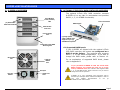
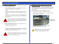
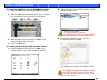
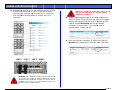
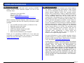
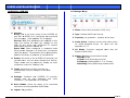
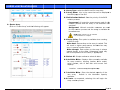
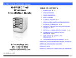
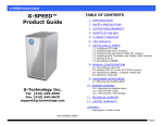
G-SPEED eS INSTALLATION GUIDE
G-SPEED™ eS
Mac Installation Guide
TABLE OF CONTENTS
1. INTRODUCTION (Pg 4)
2. SAFETY PRECAUTIONS
3. SYSTEM REQUIREMENTS
4. WHAT’S IN THE BOX
5. G-SPEED eS OVERVIEW (Pg 5)
6. OPTIONAL G-TECH PCIe RAID CONTOLLER OVERVIEW
7. G-SPEED eS AUDIBLE ALARMS (Pg 6)
8. SETTING UP G-SPEED eS WITH THE G-TECH PCIe RAID
CONTROLLER
9. G-TECH RAID CONTROLLER WEB GUI
G-Technology Inc.
Tel: (310) 449-4599
Fax: (310) 449-4670
[email protected]
(Pg 8)
10.
CHANGING THE G-TECH RAID CONTROLLER MODE (Pg 9)
11.
CONFIGURING TWO G-SPEED eS UNITS IN
RAID 5 MODE (Pg 11)
12.
WHAT TO DO IN THE EVENT OF A DISK
DRIVE FAILURE (Pg 15)
13.
TECHNICAL SUPPORT (Pg 17)
14.
LIMITED WARRANTY
APPENDIX A – DETAILED INFORMATION ON USING THE WEB GUI
APPENDIX B – EXPLANATION OF RAID LEVELS
APPENDIX C – NOTES
P/N GSPEED eS v1.2
Page 1
G-SPEED eS INSTALLATION GUIDE
Page 2
G-SPEED eS INSTALLATION GUIDE
Page 3
G-SPEED eS INSTALLATION GUIDE
1. INTRODUCTION
Thank you for purchasing G-SPEED eS from G-Technology,
Inc. (G-Tech)! Specifically designed for professional content
creation applications, G-SPEED eS features a high-speed
3Gbit/sec eSATA interface and provides RAID 0, 1, 5, 10 and
JBOD functionality when used in conjunction with the optional
G-Tech PCI Express (PCIe) RAID controller. Up to four
G-SPEED eS units can be attached to the G-Tech RAID
controller for storage capacities to 16 TB and data rates over
600 MB/sec. G-SPEED eS supports multi-stream video editing
workflows on Mac Pro workstations.
4. WHAT’S IN THE BOX
Take a moment to ensure that the following items are
included in the box. If anything is missing, please call G-Tech
at (310) 449-4599. Please keep the shipping container and
packing materials. In the unlikely event that you need to
return G-SPEED eS to us for any reason, you must use the
G-Tech shipping container. If the Product is returned
damaged caused by improper packaging, the warranty will be
void and liability will rest with the user.
If you purchased G-SPEED eS with the G-Tech PCIe
RAID controller, the system has been set up at the
factory in RAID 0 mode. The controller also supports
RAID 1, 5, 10 and JBOD modes. Refer to Section XX if you
wish to change the mode of operation.
2. SAFETY PRECAUTIONS
The disk drives contained in your G-SPEED eS are delicate
electronic instruments and are susceptible to damage due to
excessive physical shock. Place the unit in a vented area away
from moisture or liquids. Please handle the unit with care. Do
not open the case. Doing so will void the warranty. If the
Product is returned with damage caused by improper
handling, the warranty will be void and liability will rest with
the user.
•
•
•
•
•
•
•
G-SPEED eS storage system
4 removable SATA drive modules (installed in unit)
(2) disk module keys
1-meter eSATA cable
AC Power cable
Optional – G-Tech PCIe RAID controller
Configuration Utility & Installation CD
3. SYSTEM REQUIREMENTS
•
•
•
Apple Mac Pro (Intel Mac) workstation
Mac OS X 10.4.x or higher
G-Tech PCIe RAID Controller or third party port multiplier
aware eSATA host adapter
Optional G-Tech 4-port,
PCIe x4 RAID Controller
Page 4
G-SPEED eS INSTALLATION GUIDE
5. G-SPEED eS OVERVIEW
(4) Removable
Disk Drive Modules
6. OPTIONAL G-TECH PCIe RAID CONTOLLER OVERVIEW
Drive Module
Power/Activity
LED
The optional G-Tech PCIe RAID controller connects
G-SPEED eS to any Mac Pro workstation and provides
RAID 0, 1, 5, 10 & JBOD functionality.
RAID Engine
PCIe x4 interface
Disk Module
Lock Hole
Power Supply
LED
(4) High-speed
3 Gb/s eSATA ports.
Supports up to (4)
G-SPEED eS systems
Temperature/Fan RPM
Warning LED
Removable
Fan
6.1 Supported RAID Levels
If your G-SPEED eS shipped with the optional G-Tech
PCIe RAID controller, the system was configured as a
RAID 0 at the factory. The controller also supports
RAID 1, 5, 10 and JBOD configurations. If you wish to
change the RAID mode, please refer to Section 10.
3 GB/sec
eSATA
Port
AC Input
ON/ OFF
Switch
Cable Lock
Hole
For an explanation of supported RAID levels, please
refer to Appendix B.
If you purchased G-SPEED eS with the G-Tech PCIe
RAID controller, the system has been set up at the
factory in RAID 0 mode. The controller also supports RAID
1, 5, 10 and JBOD modes. Refer to Section 10 if you wish to
change the mode of operation.
G-SPEED eS is also compatible with third-party Mac &
Windows port multiplier aware eSATA host adapters. Refer to
your
host
adapter
documentation
to
set
up
G-SPEED eS with these boards.
Page 5
G-SPEED eS INSTALLATION GUIDE
7. G-SPEED eS AUDIBLE ALARMS
7.1 The G-SPEED eS enclosure is equipped with an audible
alarm that sounds when:
1. The internal temperature of the G-SPEED eS enclosure
reaches a temperature of 60° centigrade
and/or
2. When the main FAN fails or the RPM of the fan slows to
a state where the fan can longer adequately cool the
system.
8. SETTING UP G-SPEED eS WITH THE G-TECH PCIe
RAID CONTROLLER
G-SPEED eS comes pre-configured in RAID 0 mode and
formatted for MAC OS X. Connecting G-SPEED to your Mac
Pro and configuring your system takes just a few steps as
outlined below.
8.1 Installing the G-Tech PCIe RAID Controller
1. Install the G-Tech RAID controller into SLOT 4 (top slot)
of your Mac Pro workstation.
In addition to the audible alarm, the Temperature/Fan
Warning LED located on the front bezel of G-SPEED eS
will illuminate.
If you hear an audible alarm and see the RED warning LED on
the front of G-SPEED eS, stop using G-SPEED eS immediately.
Check to see if the fan is spinning and move the unit to a
cooler location. If you require a new fan, contact G-Tech
Support for a replacement.
G-Tech PCIe
RAID Controller
7.2 The G-Tech RAID controller is also equipped with an
audible alarm that sounds when:
1. A disk drive failure occurs
2. Secure the RAID controller in place.
or
2. When the G-SPEED eS is removed from the RAID
controller without first selecting “Unplug” in the Array
Maintenance menu in the web GUI.
NOTE: If you are using an AJA, Blackmagic Design or
equivalent video capture card, install it in SLOT 3
unless otherwise instructed by the card vendor.
If you hear an audible alarm coming from the G-Tech RAID
controller, see Section 12 “What to do in the Event of a Disk
Drive Failure”. See Appendix A.1.7.2 for information on the
proper way to hot “Unplug” G-SPEED eS.
Page 6
G-SPE
EED eS INSTA
ALLATION GUIDE
8.2 Attaching G-S
SPEED eS to the G-TECH RA
AID Controllerr
1. Attach one en
nd of the suppliied eSATA cable
e to the eSATA
port located on
o the back of G-SPEED
G
eS.
2 Double-click
2.
k on the “G-Tech RAID Controlller” installer
package as shown below.
2. Attach the oth
her end of the eSATA cable to Port 1 (leftmost
port) on the G-Tech
G
RAID co
ontroller as shown below.
Check fo
or software update
es at
http://w
www.g-technology.com/Support/
If you are
a
upgrading so
oftware you mustt un-install the
previou
us version first. S
See section 8.4 fo
or details
3. Attach the po
ower cord to the
e back of G-SPE
EED eS and
connect the other
o
end to AC
C power.
3 The followin
3.
ng window will a
appear. Follow the
instructions to load the sofftware.
4. Power on G-S
SPEED eS.
G
PCIe RAID
R
Controlle
er Software
8.3 Loading the G-Tech
1. Double-click on
o the G-SPEED
D eS icon locate
ed in the
“Manuals-Driv
vers” folder on the included CD as shown
below.
After restartting your system, the G-SPEED eS will
mount on yo
our desktop.
Your G-S
SPEED eS is shipp
ped from the facttory in RAID 0
mode. Th
he G-Tech RAID co
ontroller also supports RAID 1, 5,
10 and JB
BOD modes. Refer to Section 10 below
w if you wish to
change the mo
ode of operation.
Pag
ge 7
G-SPE
EED eS INSTA
ALLATION GUIDE
8.4 Uninstalling the
t
G-Tech PC
CIe RAID Conttroller Softwa
are
1. Double-click on
o the uninstall.command file located in the
“Manuals-Driv
vers” folder on the included CD as shown
above.
3. The followin
3
ng will appear in
n your browserr window.
Enter “admin” as the Userr Name and “00
000” (four
he Password and
d click on the <Login>
<
zeros) as th
button.
n and you may be prompted to
o
2. A Terminal window will open
assword to delete the installed
d driver and web
enter your pa
GUI.
ECH RAID CON
NTROLLER WE
EB GUI
9. G-TE
Th
he G-Tech RAID
D controller web
b GUI is used to
o configure and
d
mo
onitor the G-SP
PEED eS system
m. The GUI is accessed
a
using
an
ny web browserr such as Safarii, Internet Explorer or
eq
quivalent.
e G-Tech PCIe
e RAID Contro
oller Web GUI
I
9.1 Accessing the
1. Open your we
eb browser and
d enter the follo
owing address:
/localhost:740
02
https://
g window will appear. Click the
t
<Continue>
2. The following
button.
Notte: See appendix A
A.4.5 for instructio
ons on
chan
nging the password
d
NOTE: A shortc
cut has been provid
ded to access the web
w
GUI. Drag the
“G-SPEED eS Web
W
GUI” file (locate
ed in the folder Ma
anuals-Drivers\GSPEED eS\Shorttcut to Web GUI) to
t your Documents folder. Drag the
file from the Do
ocuments folder to the dock as shown
n below. Click on th
he
icon to access the web GUI.
Pag
ge 8
G-SPE
EED eS INSTA
ALLATION GUIDE
4. The main scre
een of the web GUI will appea
ar as shown
below. Note that the G-SPEE
ED eS is set up as a RAID 0.
our drives in the unit are displayed in the
Each of the fo
lower Section
n of the GUI.
10. CHANGING
C
TH
HE G-TECH RAID CONTOLLE
ER MODE
The G-SPEED eS/G-Tech RAID
T
D controller com
mbination is
c
configured
at th
he factory in RA
AID 0 mode. RAID
R
1, 5, 10 an
nd
J
JBOD
modes arre also available
e. The web GUII is used to
c
change
the mod
de of operation. Follow the diirections below to
c
change
modes.
10..1 Changing frrom RAID 0 to
o RAID 5
1 Unmount G-S
1.
SPEED eS by dragging the ico
on to the trash.
2 Launch the G-Tech
2.
G
RAID Co
ontroller web GUI.
3 Click on the “Maintenance”
3.
“
Link. The wind
dow shown belo
ow
will appear.
NOTE: Please
e refer to APPENDIIX A for detailed infformation on the
features of th
he G-Tech RAID Co
ontroller web GUI.
Pag
ge 9
G-SPE
EED eS INSTA
ALLATION GUIDE
4. Click on the <DELETE>
<
buttton. The following window
will appear. Click
C
the <OK> button to proce
eed.
7. Select RAID
7
D 5 for “Array T
Type:”, enter G--SPEEDeS-R5
for “Array Name:”, select F
Foreground an
nd Write Back
k
olicy:”
for “Initialization Method:”” and “Cache Po
y and click the <
<Select All> bu
utton.
respectively
WARNING:
W
This will delete any data
stored on G-SPEED eS!
e
r
and the
e array is now deleted.
d
5. The GUI will refresh
NOTE: In
n this example we a
are creating a RAID
D 5. The system
can also be
b set up in RAID 1
1, 10 or JBOD mode by selecting the
appropriate setting in the “A
Array Type:” pull-down menu.
Create Array> button.
6. Click the <C
window will appear.
The “Create Array
y”
Page
e 10
G-SPE
EED eS INSTA
ALLATION GUIDE
8. Click
C
the <Crea
ate> button. Th
he following win
ndow will appea
ar.
9. C
Click the <OK>
> button. The following
f
windo
ow will appear.
T
The
GUI will ind
dicate that the G-SPEED eS is initializing.
11. The Mac OS
S will display th
he “Disk Insertiion” window
indicating the
t
G-SPEED eS
S is now ready to be initialized
d.
Click on the
e <Initialize> b
button to launch the Apple Dis
sk
Utility and refer to your sy
ystem documen
ntation for
s.
instructions
11. CONFIGURING
C
G TWO G-SPEE
ED eS UNITS IN
I RAID 5 MO
ODE
Each G-SPEED eS unit is configured at the fa
E
actory with the
G
G-Tech
RAID co
ontroller in RAID
D 0 mode. RAIID 1, 5, 10 and
d
J
JBOD
modes arre also available
e. The web GUII is used to
c
change
the mod
de of operation
n. Follow the diirections below to
c
configure
two G-SPEED
G
eS arrrays in RAID 5 mode using the
e
G
G-Tech
RAID co
ontroller.
AID controller is properly
1. Ensure that the G-Tech RA
nd the driver an
nd web GUI are
e loaded.
installed an
h G-SPEED eS u
units to the G-T
Tech RAID
2. Attach both
controller as
a shown below
w, power the un
nits and restart
your compu
uter
10.The
T
RAID 5 inittialization proce
ess takes appro
oximately 1:45
p TB of final capacity.
per
c
Once
e the initializatio
on process is
c
complete,
the GUI
G will indicate
e “Type” as RA
AID 5 and
“
“Status”
as Nor
rmal .
ms will mount o
on the desktop.
3. Both system
Page
e 11
G-SPE
EED eS INSTA
ALLATION GUIDE
4. U
Unmount both G-SPEED eS un
nits by dragging
g the icons to
t
the
trash.
6. Click on the “Maintenance” link next to the array with “OS
S
sk 1_0. The wiindow shown below will appea
ar.
Name” GS Dis
5. L
Launch the G-T
Tech RAID Controller web GUI.. With the two
u
units
attached to
t the G-Tech RAID
R
controller,, the GUI will
d
display
informa
ation like that shown below.
7. Click the <De
elete> button. The following window
w
will appear.
WA
ARNING: This will delete any data
stored on G-SPEED eS
S.
Page
e 12
G-SPE
EED eS INSTA
ALLATION GUIDE
8. Click the <OK
K> button to de
elete the array.
e array with “OS
S
9. Click on the “Maintenance” link next to the
sk 1_1. The window below will appear.
Name” GS Dis
elete> button and the follow
wing window will
10. Click the <De
appear.
11
1. Click the <OK>
<
button to delete the array. Both
arrays have now been deleted as s
shown below.
2. Click the <C
Create Array> b
button. The “C
Create Array”
12
window will appear.
WA
ARNING: This will delete any data
sto
ored on G-SPEED eS.
e
Page
e 13
G-SPE
EED eS INSTA
ALLATION GUIDE
13. Select RAID 5 for “Array Type:”, enter G-S
SPEED-eSR5 for “Array Name:”, selectt Foreground and Write
hod:” and “Cach
he Policy:”
Back for “Inittialization Meth
respectively and
a
click the <S
Select All> buttton then
Click the <Cre
eate> button.
14
4. The followin
ng window will a
appear.
15
5. Click the <O
OK> button. Th
he following window will appear
to indicate that
t
the G-SPEE
ED eS is initializ
zing.
Page
e 14
G-SPE
EED eS INSTA
ALLATION GUIDE
15. The RAID 5 in
nitialization pro
ocess takes app
proximately 1:4
45
per TB of fina
al capacity. Onc
ce the initialization process is
complete, the
e GUI will indica
ate “Type” as RAID
R
5 and
“Status” as Normal.
N
The GUI will display
d
information like that sh
hown below. An
n
exclamation mark
m
on the G-SPEED eS icon indicates that
the “Status” of
o the array is C
Critical. The lower portion of
the GUI indica
ates which drive in which G-SPEED eS unit
has failed.
w display the “Disk Insertion
n” window
16. The Mac OS will
indicating the
e G-SPEED eS is
s now ready to be initialized.
Click on the <Initialize>
<
buttton to launch the
t
Apple Disk
Utility and reffer to your systtem documenta
ation for
instructions.
12. WH
HAT TO DO IN THE EVENT OF
O A DISK DRI
IVE FAILURE
Th
he G-Tech RAID controller conttinually monitors the health off
ea
ach of the disk drives
d
in G-SPE
EED eS. In the event of a disk
k
faiilure, an audible alarm will sou
und. The web GUI will also
report the failed drive and its ph
hysical position
n.
NOTE: If G-SPEED eS was
s configured in a prrotected
RAID mode (RAID 1, 5 or 10), a drive failure
e does not
result in
n data loss. Howev
ver, the array is no
ow in an
unprotected state and the failed drive should
d be
replaced
d as soon as possib
ble to avoid data lo
oss.
Fo
ollow the steps below to identify and replace a failed drive.
1 Launch the web GUI.
1.
In this
t
example there are two G-SPEED eS units
connected to the G-Te
ech RAID controllerr. Drive 3 of
the G-SPEED eS conne
ected to Port 2 of the
t
G-Tech
RAID controller has fa
ailed.
2 Mute the ala
2.
arm by clicking
g on the <Beepe
er Mute>
button.
Page
e 15
G-SPE
EED eS INSTA
ALLATION GUIDE
3 Remove the
3.
e failed drive (In this example Drive 3, of the
e
G-SPEED eS
S connected to port 2 of the G-Tech
G
RAID
controller) by
b inserting the
e provided key in to the lock
hole and ge
ently sliding the
e drive module out of the
enclosure.
REMOVING THE W
R
WRONG DRIVE WI
ILL RESULT IN THE
L
LOSS
OF THE ARR
RAY AND ALL OF THE
T
CONTENT
S
STORED
ON G-SPE
EED eS.
he failed drive w
with a new disk
k module and
4. Replace th
secure in place. Once th
he drive has spu
un up to speed,,
w indicate thatt the array is re
ebuilding (The
the GUI will
“Status” shows Rebuildiing and the percentage
ow. The rebuild
d time is
complete) as shown belo
ately 2 hours pe
er TB.
approxima
r
is comp
plete, G-SPEED eS is back to
5. Once the rebuild
Normal and protecting y
your valuable data once again.
X
WAR
RNING: Make absollutely sure that you
u remove the failed
d
drive indicated by the GUI.
G
If multiple G-S
SPEED eS units are
e
conne
ected to the G-Tech
h RAID controller, it is a good idea to
o
follow
w the cable to ensure you know which
h Port # the array is
i
conne
ected to on the RAIID controller.
Page
e 16
G-SPEED eS INSTALLATION GUIDE
13. TECHNICAL SUPPORT
If you encounter any difficulties while installing G-SPEED,
please contact G-Tech Technical Support via one of the
following ways:
Telephone: (310) 449-4599
Fax: (310) 449-4670
E-mail: [email protected]
Internet: http://www.g-technology.com/support
When contacting Technical Support, make sure to be in front
of your computer and have the following information readily
available:
•
•
•
•
•
•
Your G-SPEED eS serial number (on bottom of unit)
Operating system and version
Computer brand and model
eSATA host adapter brand and model
Amount of memory installed
Other devices attached to your computer
Thank you for purchasing G-SPEED eS. If you have any
comments or questions about this manual or the Product,
please call (310) 449-4599, or send an email to
[email protected].
14. LIMITED WARRANTY
G-Technology Inc. (G-Tech) warrants your Product against
any defect in material and workmanship, under normal
use, for the designated warranty period. If the Product
should become defective within the warranty period,
G-Tech, will at its discretion, repair or replace the Product.
Repair or replacement parts or Products will be furnished
on an exchange basis and will be either new or
reconditioned. All replaced parts or Products shall become
the Property of G-Tech. This warranty shall not apply if the
Product has been damaged by accident, misuse, abuse or
as a result of unauthorized service or parts. Warranty
service is available to the purchaser by obtaining a Return
Material Authorization number (RMA) and by delivering
the Product during the warranty period to an authorized
G-Tech service facility or to G-Tech. The purchaser shall
bear all shipping, packing and insurance costs and all
other costs, excluding parts and labor, necessary to
effectuate repair, replacement or refund under this
warranty. All returned Product must be shipped to
G-Tech in the original shipping container.
For more information on how to obtain warranty service,
an RMA number or to acquire shipping materials, contact
G-Tech at 1653 Stanford Street, Santa Monica, CA 90404,
(310) 449-4599 or [email protected].
IN THE EVENT A PRODUCT BECOMES DEFECTIVE DURING
THE WARRANTY PERIOD, THE PURCHASER’S EXCLUSIVE
REMEDY SHALL BE REPAIR OR REPLACEMENT AS
PROVIDED ABOVE. INCIDENTAL OR CONSEPROUENTAL
DAMAGES, INCLUDING WITHOUT LIMITATION LOSS OF
DATA, ARISING FROM BREACH OF ANY EXPRESS OR
IMPLIED WARRANTY ARE NOT THE RESPONSIBILITY OF GTECH AND, TO THE EXTENT PERMITTED BY LAW, ARE
HEREBY EXCLUDED BOTH FOR PROPERTY DAMAGE, AND
TO THE EXTENT NOT UNCONSCIONABLE, FOR PERSONAL
INJURY DAMAGE.
Page 17
G-SPE
EED eS INSTA
ALLATION GUIDE
APPE
ENDIX A: WEB
B GUI
A.1 Manage: Array
A
A
name (as shown in GUI only).
1. Name: Array
1 Manage:
1.
s is the main screen of the G-SPEED eS
Array: This
web GUI. G-SPEED
G
eS is configured an
nd monitored
from this pa
age. (See Appe
endix A.1 for de
etails)
Devices: Hard
H
drive param
meters are mod
dified on this
page (you should not make
m
any chan
nges on this
t
drives are
e configured for optimal
page as the
performance with the G-SP
PEED eS.
ol: When conffigured in prottected mode
Spare Poo
drives can be
b assigned to a “spare pool”” (sometimes
called hot spare).
s
These drives
d
will be automatically
a
added to the Array in the event
e
of a drive
e failure.
2 Events: All events of the G-SPEED eS controller
2.
c
are
ere, such as array
a
changes and failures.
recorded he
These even
nts can be em
mailed by settin
ng up email
notification under the “Setttings” tab.
vel of array.
2. Type: Displays RAID lev
y: you guessed it… capacity off the array.
3. Capacity
P
Displays current write
e cache policy
4. Cache Policy:
for RAID
D protected a
arrays. For more
m
info see
appendix
x A.1.7.7
me: Controllerr assigned na
ame that will
5. OS Nam
display in
n Disk Utility.
D
curren
nt status of arra
ay.
6. Status: Displays
Norma
al: All OK
Critica
al: Drive failure
e has occurred
Initiallizing: Building
g RAID 1, 5 or 10 array
Rebuiilding: Parity data being recon
nstructed
3 Tasks: Schedule the G-Tech controller to
3.
o
R
automatically verify the inttegrity of the RAID
volume.
4 Settings: Configure the
4.
e G-SPEED eS controller
settings such as login password and email
x A.4 for details
s
notification.. See Appendix
5 Drive Stattus: Check the status of all connected
5.
hard drives including detaiiled SMART datta.
6 Logout: Sa
6.
ay goodbye
Page
e 18
G-SPE
EED eS INSTA
ALLATION GUIDE
7.4 OCE/ORL
LM:
Online Capacity Expansio
on: It is possible to expand th
he
o an existing arrray when additional
capacity of
G-SPEED eS
e units are ad
dded to the systtem.
Online RA
AID Level Migra
ation: it is poss
sible to change
the RAID level of an exis
sting array.
e: Displays configuration and maintenance
7. Maintenance
options for cu
urrent array. Th
he options diffe
er depending
on RAID levell of the array.
RAID 0
e devices curre
ently part of the
t
Array, theirr
7.5 Shows the
location an
nd status.
“Devic
ce_Controller
r#_Port#_Driv
ve#”
RAID 5
D
currentt Array
7.1 Delete: Deletes
NING: THIS OPERATION WILL DELET
TE
WARN
THE ARRAY
A
AND AL
LL DATA ON IT!!
sconnect the Array
A
from th
he
7.2 Unplug: This will dis
B sure to un
nmount all volumes from th
he
controller. Be
system before using this op
ption. This ena
ables the array
ys
gged from the
e system without causing an
a
to be unplug
alarm.
NOTE: While the conttroller is “hot pluggable,”
p
we
recomm
mend shutting the system down when connecting or
disconne
ecting G-SPEED eS
S from the controlle
er.
ay as displayed in the GUI.
7.3 Rename: Renames arra
7.6 Verify: Ve
erifies the integ
grity of the RAID
D set.
C
Policy: This option is available for
7.7 Change Cache
RAID 5 arrays..
Write-b
back: Data written to th
he array is
cached.. This will resu
ult in higher performance,
p
but datta loss may o
occur in case of a power
failure.
Write-tthrough: Data written to the
t
array is
always passed directly
y to the disks. Subsequent
reads may
m
still be com
mpleted from the
t
cache, if
approprriate
Page
e 19
G-SPE
EED eS INSTA
ALLATION GUIDE
8.1 Array Type
e: select the RA
AID level for new
w array
8.2 Array Nam
me: This is the name that wiill be displayed
d in
the MAIN pa
age of the GUI.
8.3 Initializatio
on Method: Se
ets the priority of the RAID
creation pro
ocess.
Create Array
8. C
C
Click
on “Create Array” and the
e following will appear.
Foregrou
und: All controlller resources are
a used for th
he
creation process
p
and th
he array is nott available unttil
complete.
Backgrou
und: Minimal controller reso
ources are use
ed
for the cre
eation process and the array
y is available fo
or
immediate
e use.
NOT
TE: RAID protection is not available
until initialization is complete
8.4 Cache Polic
cy: This option
n is available when creating
a RAID 5 arrray.
Write-back: Data written tto the array is cached. This
n higher performance, but da
ata loss may
will result in
occur in case
e of a power faiilure.
Write-throu
ugh: Data writtten to the arra
ay is always
passed direc
ctly to the disk
ks. Subsequentt reads may
still be completed from the cache, if appro
opriate
8.5 Select All: Simple method
d to select all diisks.
8.6 Available Disks:
D
Display
ys disks curren
ntly available
for array creation,
c
showiing location, drive
d
model,
serial numb
ber, size of th
he disk and current
c
free
capacity.
#/Port#/Drive
e#”
Location: “Controller#
8.7 Available Disks:
D
Enter tthe desired cap
pacity of the
new array.
Default is
s the Maximu
um capacity
available.
8.8 Create: As
s expected, se
electing this wiill begin the
array creatio
on process.
Page
e 20
G-SPE
EED eS INSTA
ALLATION GUIDE
9. Lo
ocation: Show
ws the location of
o disks attache
ed to the
controller.
Lo
ocation: “Contr
roller#/Port#/
/Drive#”
10. Mo
odel: Displays
s the drive mo
odel and serial number of
dis
sks currently atttached to the controller.
c
(This page left inte
entionally blan
nk)
11. Ca
apacity: Displa
ays the advertised capacity of
o the disks
currently attache
ed to the contro
oller.
12. Ma
ax Free: Displays the maxim
mum free capa
acity of the
dis
sks currently atttached to the controller.
c
13. Re
escan: Rescan
ns the eSATA bus to detectt any new
de
evices attached.
14. Be
eeper Mute: Mutes
M
audible be
eeper.
NOTE: Beepe
er will sound when a drive fails or an array
a
is
disconnected from the system without
w
first selectin
ng
“Unplug” in th
he Array Maintenan
nce menu.
Page
e 21
G-SPE
EED eS INSTA
ALLATION GUIDE
Appendix A.4: Settings
1. Auto Rebuild
d: Enables orr disables the auto-rebuild
feature. Whe
en enabled, a critical RAID 5 or RAID 1
array will auttomatically reb
build when a new
n
drive is
inserted. See
e Section 12 forr details.
2. Audible Alarrm: Enables orr disables the audible alarm
3. SAF-TE: This
s feature is not currently suppo
orted.
4. Listening Po
ort: The port used to connect to the
G-SPEED web
b GUI. “Restric
ct to local acce
ess” disables
network users
s to access the GUI. Default is
i Port 7402.
5. Password: Changes
C
login p
password. Defau
ult is 0000
6. SMTP Settin
ng: Email serrver informatio
on necessary
for email nottification. Ente
er your server information
here.
nts.
7. Recipients: A list of currentt email recipien
ent: Add em
mail addresses
s for email
8. Add Recipie
notification. Select
S
Event lev
vel to trigger an email.
Information: Informational events are sent
arning events a
are sent
Warning: Wa
Error: Error events
e
are sentt
nt
Test: Sends a test email to the new accoun
hold: Adjusts the threshold
9. HDD Temperrature Thresh
of the hard drive temperature to trigger a warning
ult is 50°C, ho
owever today’s
s disk drives
email. Defau
can operate up
u to 60°C.
Page
e 22
G-SPEED eS INSTALLATION GUIDE
APPENDIX C: Notes
APPENDIX B: RAID levels explained
RAID
Level
0
1
5
Description
Disk striping
Mirroring
Disk striping
with
distributed
parity
Advantage
Offers the highest
performance and a
useable storage
capacity of 100%
of total available
storage capacity
Maximum level of
data protection as
identical data is
written to multiple
drives
High read
performance,
medium write
performance with
data protection in
case of a drive
failure.
Disadvantage
No fault tolerance failure of one drive
in the array results
in complete data
loss
Ideal For…
Content creation
applications
requiring highest
storage capacity
Useable storage
space is 50% of
total available
capacity
Applications in
which data
security is
paramount
Useable storage
capacity equals
total capacity of all
drives in the array
less the capacity of
one drive.
Content creation
applications
requiring data
protection
When the G-Tech web GUI is open dropped frames
may occur in editing applications such as Final Cut
Pro. We recommend not having the GUI open while
working in these programs.
It is recommended not to exceed the standard eSATA
cable length of 1 meter (3 feet).
Up to (4) G-SPEED eS storage units can be attached
to the G-Tech RAID controller for up to 16TB of
capacity and over 600 MB/sec of performance.
Replacements / extra G-SPEED eS disk modules are
available for purchase online at:
www.g-technology.com/products/g-speed-es.cfm
For example, a 4x
1TB RAID 5 yields
a useable capacity
of 3 TB.
10
JBOD
Mirror of
striped drive
pairs
Just-abunch-ofdisks
Higher
performance than
RAID 1 with same
level of data
protection.
Each drive can be
accessed as an
individual volume.
Useable storage
capacity is 100%
of total available
storage.
Disk failure results
in drop in
performance
Useable storage
space is 50% of
total available
capacity
No fault tolerance
Content creation
applications
requiring data
protection
Audio
applications
Page 23