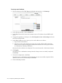
1
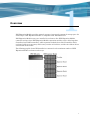
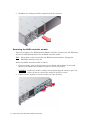
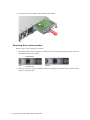
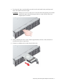
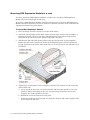
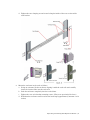
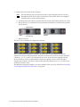
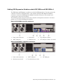
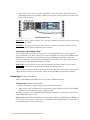
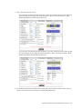
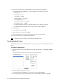
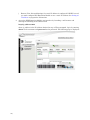
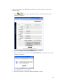
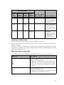
Installation and
Administration Guide
Tandberg Data™ DPS Expansion Module
April 2009
Contents
Preface . . . . . . . . . . . . . . . . . . . . . . . . . . . . . . . . . . . . . . . . . . . . . . . . . . . . . . . . . . . . . . . . . . . . . . .v
About this guide . . . . . . . . . . . . . . . . . . . . . . . . . . . . . . . . . . . . . . . . . . . . . . . . . . . . . . . . . . . . . . v
Audience . . . . . . . . . . . . . . . . . . . . . . . . . . . . . . . . . . . . . . . . . . . . . . . . . . . . . . . . . . . . . . . . . . . . v
Typographical conventions . . . . . . . . . . . . . . . . . . . . . . . . . . . . . . . . . . . . . . . . . . . . . . . . . . . . . v
Related documentation . . . . . . . . . . . . . . . . . . . . . . . . . . . . . . . . . . . . . . . . . . . . . . . . . . . . . . . .vi
Support . . . . . . . . . . . . . . . . . . . . . . . . . . . . . . . . . . . . . . . . . . . . . . . . . . . . . . . . . . . . . . . . . . . . .vi
1
Overview . . . . . . . . . . . . . . . . . . . . . . . . . . . . . . . . . . . . . . . . . . . . . . . . . . . . . . . . . . . . . . . . . . . . .1
2
Unpacking and Cabling DPS Expansion Module . . . . . . . . . . . . . . . . . . . . . . . . . . . . . . . . . .3
Unpacking DPS Expansion Module . . . . . . . . . . . . . . . . . . . . . . . . . . . . . . . . . . . . . . . . . . . . . . 3
DPS Expansion Module box contents . . . . . . . . . . . . . . . . . . . . . . . . . . . . . . . . . . . . . . . . . . 3
Additional items needed for installation . . . . . . . . . . . . . . . . . . . . . . . . . . . . . . . . . . . . . . . 4
Preparing DPS Expansion Module for mounting . . . . . . . . . . . . . . . . . . . . . . . . . . . . . . . . . . . . 4
Removing the power supply modules . . . . . . . . . . . . . . . . . . . . . . . . . . . . . . . . . . . . . . . . . . 5
Removing the cooling fan module . . . . . . . . . . . . . . . . . . . . . . . . . . . . . . . . . . . . . . . . . . . . . 5
Removing the RAID controller module . . . . . . . . . . . . . . . . . . . . . . . . . . . . . . . . . . . . . . . . 6
Removing the disk I/O module . . . . . . . . . . . . . . . . . . . . . . . . . . . . . . . . . . . . . . . . . . . . . . . 7
Removing drive carrier modules . . . . . . . . . . . . . . . . . . . . . . . . . . . . . . . . . . . . . . . . . . . . . . 8
Mounting DPS Expansion Module in a rack . . . . . . . . . . . . . . . . . . . . . . . . . . . . . . . . . . . . . . 10
Installing DPS Expansion Module modules . . . . . . . . . . . . . . . . . . . . . . . . . . . . . . . . . . . . . . . 13
Installing the power supply modules . . . . . . . . . . . . . . . . . . . . . . . . . . . . . . . . . . . . . . . . . 13
Installing the cooling fan module . . . . . . . . . . . . . . . . . . . . . . . . . . . . . . . . . . . . . . . . . . . . 14
Installing the RAID controller modules . . . . . . . . . . . . . . . . . . . . . . . . . . . . . . . . . . . . . . . 15
Installing the disk I/O modules . . . . . . . . . . . . . . . . . . . . . . . . . . . . . . . . . . . . . . . . . . . . . 17
Installing drive carrier modules . . . . . . . . . . . . . . . . . . . . . . . . . . . . . . . . . . . . . . . . . . . . . 18
Cabling DPS Expansion Module models XDC1200a and XDS1200a-1 . . . . . . . . . . . . . . . . . . 21
Connecting DPS Expansion Module to DPS1000 Series and expansion enclosures . . . . . . . 22
Enabling access to the serial command line interface . . . . . . . . . . . . . . . . . . . . . . . . . . . . . . . 23
Enabling access to the network . . . . . . . . . . . . . . . . . . . . . . . . . . . . . . . . . . . . . . . . . . . . . . . . . 23
Connecting power . . . . . . . . . . . . . . . . . . . . . . . . . . . . . . . . . . . . . . . . . . . . . . . . . . . . . . . . . . . . 23
Powering DPS Expansion Module . . . . . . . . . . . . . . . . . . . . . . . . . . . . . . . . . . . . . . . . . . . . . . . 24
3
Configuring DPS Expansion Module . . . . . . . . . . . . . . . . . . . . . . . . . . . . . . . . . . . . . . . . . . . .25
Accessing the serial console . . . . . . . . . . . . . . . . . . . . . . . . . . . . . . . . . . . . . . . . . . . . . . . . . . . . 25
Setting an IP address . . . . . . . . . . . . . . . . . . . . . . . . . . . . . . . . . . . . . . . . . . . . . . . . . . . . . . . . . 25
Setting a dynamic IP address . . . . . . . . . . . . . . . . . . . . . . . . . . . . . . . . . . . . . . . . . . . . . . . 26
Setting a static IP address . . . . . . . . . . . . . . . . . . . . . . . . . . . . . . . . . . . . . . . . . . . . . . . . . 26
Determining the DPS Expansion Module IP address . . . . . . . . . . . . . . . . . . . . . . . . . . . . . . . 27
Accessing the DPS Expansion Module web interface . . . . . . . . . . . . . . . . . . . . . . . . . . . . . . . 27
Accessing Help . . . . . . . . . . . . . . . . . . . . . . . . . . . . . . . . . . . . . . . . . . . . . . . . . . . . . . . . . . . . . . 27
Setting up email notices . . . . . . . . . . . . . . . . . . . . . . . . . . . . . . . . . . . . . . . . . . . . . . . . . . . . . . 27
4
Installing and Configuring Additional Enclosures . . . . . . . . . . . . . . . . . . . . . . . . . . . . . . . .29
Adding arrays and enclosures to a DPS1000 Series configuration . . . . . . . . . . . . . . . . . . . . . 29
Creating arrays . . . . . . . . . . . . . . . . . . . . . . . . . . . . . . . . . . . . . . . . . . . . . . . . . . . . . . . . . . . . . 30
Creating logical drives . . . . . . . . . . . . . . . . . . . . . . . . . . . . . . . . . . . . . . . . . . . . . . . . . . . . . . . . 32
Contents | iii
Designating hot spares . . . . . . . . . . . . . . . . . . . . . . . . . . . . . . . . . . . . . . . . . . . . . . . . . . . . . . . 33
Backing up the configuration . . . . . . . . . . . . . . . . . . . . . . . . . . . . . . . . . . . . . . . . . . . . . . . . . . 33
5
Troubleshooting . . . . . . . . . . . . . . . . . . . . . . . . . . . . . . . . . . . . . . . . . . . . . . . . . . . . . . . . . . . . . .35
A
Upgrading DPS Expansion Module . . . . . . . . . . . . . . . . . . . . . . . . . . . . . . . . . . . . . . . . . . . . .41
B
Technical Specifications . . . . . . . . . . . . . . . . . . . . . . . . . . . . . . . . . . . . . . . . . . . . . . . . . . . . . .47
C
LEDs and Alarms . . . . . . . . . . . . . . . . . . . . . . . . . . . . . . . . . . . . . . . . . . . . . . . . . . . . . . . . . . . . .53
LEDs . . . . . . . . . . . . . . . . . . . . . . . . . . . . . . . . . . . . . . . . . . . . . . . . . . . . . . . . . . . . . . . . . . . . . . 53
Alarms . . . . . . . . . . . . . . . . . . . . . . . . . . . . . . . . . . . . . . . . . . . . . . . . . . . . . . . . . . . . . . . . . . . . 58
Index . . . . . . . . . . . . . . . . . . . . . . . . . . . . . . . . . . . . . . . . . . . . . . . . . . . . . . . . . . . . . . . . . . . . . . . .61
iv | Contents
Preface
Welcome to the DPS Expansion Module Installation and Administration Guide. Tandberg
Data DPS Expansion Module is an external storage array that provides additional storage for
Tandberg Data DPS1000 Series™. This guide enables you to install and configure DPS
Expansion Module.
About this guide
The DPS Expansion Module Installation and Administration Guide is designed to help you
unpack, rack-mount, cable, power, and configure DPS Expansion Module.
The following chapters are included:
•
Overview — Provides an introduction to DPS Expansion Module
•
Unpacking and Cabling DPS Expansion Module — Describes the contents shipped with
DPS Expansion Module as well as how to rack-mount, cable, and power DPS Expansion
Module
•
Configuring DPS Expansion Module — Describes how to configure DPS Expansion
Module through its web interface
•
Installing and Configuring Additional Enclosures — Describes how to install and
configure DPS Expansion Module expansion enclosures not shipped with the DPS
Expansion Module controller
•
Troubleshooting — Describes problems you might encounter while operating DPS
Expansion Module and provides suggestions for resolving the problems
In addition, the following appendices are included:
•
Upgrading DPS Expansion Module — Describes how to upgrade the DPS Expansion
Module firmware and software
•
Technical Specifications — Lists the technical specifications for DPS Expansion Module
•
LEDs and Alarms — Lists details about the LEDs and alarms that communicate DPS
Expansion Module status
Audience
This guide is designed for use by anyone installing and using DPS Expansion Module. Users
connecting DPS Expansion Module to DPS1000 Series should be familiar with their SAS
environment and DPS1000 Series.
Typographical conventions
This guide uses the following typographical conventions:
Convention
Description
Bold
Used for file names, field names, URLs, interface elements
that are clicked/selected, and information that must be used
literally.
Preface | v
Convention
Description
Bold Italic
Represents variables within file names, command syntax,
URLs, or other literal text.
Italics
Used for emphasis, book titles, and variables.
Monospace
Used for text that is displayed on-screen, command names
and arguments (syntax), code, and command-line text.
Monospace Italic
Represents variables within command syntax, code, or
command-line text.
Blue Text
Used for cross-references.
Related documentation
As you install DPS Expansion Module, you may want to refer to the DPS1000 Series
Installation Guide, which provides information about deploying DPS1000 Series.
Support
For service and support assistance, contact your authorized service and support representative
directly. For Technical Support, refer to http://www.tandbergdata.com/.
vi | Preface
Overview
DPS Expansion Module provides external storage to increase the amount of storage space for
virtual tapes. DPS Expansion Module is compatible with DPS1000 Series.
DPS Expansion Module arrays are installed in enclosures. One DPS Expansion Module
controller and up to four DPS Expansion Module expansion modules can be cabled together.
Controllers have RAID controllers, while expansion modules have disk I/O modules. Each
enclosure holds up to two arrays. Each array consists of six drives, and the size of these drives
varies based on the model.
The following graphic shows DPS1000 Series connected to the maximum number of DPS
Expansion Module enclosures and arrays:
1
The following DPS Expansion Module models are compatible with DPS1000 Series:
Model
Enclosure
Type
Connections
Storage
Per Array
Physical Disk
Capacity
XDC1200a
SAS
Controller
• SAS connection to
DPS1000 Series
• SAS connection to
other DPS
Expansion Module
enclosures
3.75TB*
4.5TB
XDS1200a-1
SAS
Expansion
• SAS connection to
DPS1000 Series
• SAS connection to
other DPS
Expansion Module
enclosures
3.75TB*
4.5TB
*
Available space for data storage is 6.8TB after the file system is initialized, assuming 2:1 data
compression.
Arrays are preconfigured on the DPS Expansion Module controller and any DPS Expansion
Module expansion modules shipped with it. You must configure arrays for any DPS
Expansion Module expansion modules or drives shipped separately. For information about
this installation and configuration, see Installing and Configuring Additional Enclosures on
page 29.
2 | Overview
Unpacking and Cabling DPS Expansion Module
This section provides instructions for unpacking DPS Expansion Module, placing it in a rack,
and cabling it to DPS1000 Series, the network, and a power source.
Note
If you are currently using DPS Expansion Module as external storage and you are
upgrading DPS1000 Series, you must also upgrade the DPS Expansion Module
firmware. See Upgrading DPS Expansion Module on page 41 for more information.
Unpacking DPS Expansion Module
Use the following steps as you unpack DPS Expansion Module from its box:
1. Unpack DPS Expansion Module carefully and retain all packing materials.
2. Inspect DPS Expansion Module and its box contents. If any damage is apparent, contact
Support.
3. Place DPS Expansion Module on a flat, stable work surface.
DPS Expansion Module box contents
The DPS Expansion Module box contains the following items:
•
DPS Expansion Module enclosure with 12 drives or six drives and six dummy carriers
•
Three (3) sets of two power cords (United States, European, and other)
•
RS232 serial cable
•
SAS patch cable
•
Rail kit
•
Eight (8) M5 spring washers (tapped hole rack)
•
Eight (8) ATX rack slide washers with square holes (square hole rack)
•
Two (2) ATX chassis slides
•
Eight (8) ATX rack slide washers with round holes (round hole rack)
•
Ten (10) M3 x 4 buttonhead oxide patchlocks (all racks)
•
Two (2) ATX chassis latches (all racks)
•
Two (2) Screw ATX chassis latches (all racks)
•
Eight (8) M5 x 12 CSK Phillips patchlocks (all racks)
•
Eight (8) Screws 10-32 UNF special Phillips (tapped hole rack)
•
One (1) Hex Allen key driver 2 mm (all racks)
3
•
•
Two (2) ATX rack bracket assemblies universal
•
One (1) 10 mm spanner (tapped hole rack)
Anti-tamper lock tool
Additional items needed for installation
Gather the following items before you begin installing and configuring DPS Expansion
Module:
•
Terminal or computer running a terminal emulation program
•
Ethernet cable for controller enclosure
•
SAS patch cable for each expansion module (in addition to the SAS patch cable shipped
with the enclosure)
Preparing DPS Expansion Module for mounting
Several plugin modules (such as the power supplies, the drive carriers, and so on) are
installed in the DPS Expansion Module enclosure. When fully populated, DPS Expansion
Module is very heavy (32 kg / 70.4 lb.). Because of this, it is highly recommended that you
remove the DPS Expansion Module plugin modules before you mount the enclosure in a rack
and that you use an assistant during the installation.Also, you may want to use an anti-static
wrist strap during installation.
WARNING Observe all conventional ESD precautions when handling DPS Expansion
Module modules and components. Avoid contact with backplane components,
module connectors, and so on.
4 | Unpacking and Cabling DPS Expansion Module
Removing the power supply modules
Remove each power supply module as follows:
1. Push the latch above the power supply handle to the right.
2. Grip the handle and pull the module out of the enclosure.
WARNING Do not remove the covers from the power supply. There is a danger of
electric shock inside.
Removing the cooling fan module
Remove the cooling fan module as follows:
1. Grasp the latch between your thumb and forefinger. Squeeze your thumb and forefinger
together to release the latch.
2. Pull the latch outward to eject the module out of the enclosure.
Unpacking and Cabling DPS Expansion Module | 5
3. Withdraw the cooling fan module completely from the enclosure.
Removing the RAID controller module
This section applies to the DPS Expansion Module controller enclosure only. The XDC1200a
model used with DPS1000 Series has one RAID controller module.
Note
The graphics in this section show two RAID controller modules, although the
XDC1200a model has only one.
Remove the RAID controller module as follows:
1. Using two hands, grasp each latch between your thumb and forefinger of each hand.
Squeeze your thumbs and forefingers together to release the latches.
CAUTION Handle the module carefully and avoid damaging the connector pins. You
will not be able to reinstall the module if any pins are bent.
2. Pull the latches outward to eject the module out of the enclosure.
6 | Unpacking and Cabling DPS Expansion Module
3. Grip the latches as handles and withdraw the RAID controller module.
Removing the disk I/O module
This section applies to the DPS Expansion Module expansion enclosures only. The XDS1200a1 model used with DPS1000 Series has one disk I/O module.
Note
The graphics in this section show two disk I/O modules, although the XDS1200a-1
model has only one.
Remove the disk I/O module as follows:
1. Using two hands, grasp each latch between your thumb and forefinger of each hand.
Squeeze your thumbs and forefingers together to release the latches.
2. Pull the latches outward to eject the module out of the enclosure.
Unpacking and Cabling DPS Expansion Module | 7
3. Grip the latches as handles and withdraw the module.
Removing drive carrier modules
Remove drive carrier modules as follows:
1. If the anti-tamper lock is engaged, carefully insert the lock key provided into the cutout in
the handle and into its socket.
2. Rotate the key in a counter-clockwise direction until the red indicator is not visible in the
aperture beside the key.
8 | Unpacking and Cabling DPS Expansion Module
3. To release the drive carrier handle, press the latch in the handle with your finger and
rotate the handle towards the right.
CAUTION Damage can occur to a drive if it is removed while still spinning. You should
perform all steps of the following procedure to ensure that the drive has
stopped prior to removal.
4. Gently withdraw the drive carrier module approximately 25 mm (1 inch) and wait 30
seconds for the drive to spin down.
5. Continue to withdraw the module from the drive slot.
Unpacking and Cabling DPS Expansion Module | 9
Mounting DPS Expansion Module in a rack
You must mount the DPS Expansion Module enclosure in a rack. Each DPS Expansion
Module enclosure requires 2U of rack space.
If you have a DPS Expansion Module controller enclosure and one or more DPS Expansion
Module expansion enclosures, be sure to mount the controller enclosure in the rack above the
expansion enclosures for easier cabling.
To mount DPS Expansion Module
1. Place the empty enclosure chassis on a stable work surface.
2. Attach the left and right chassis slides to the enclosure sides using a total of six M3 x 4
button head screws, three on each side. The front portion of the chassis slide has two
tangs that insert into holes on the forward edge of the side panel.
3. Assemble the left and right chassis latches using the chassis latch screws (supplied).
Ensure that the latch is oriented as shown in the following figure, with the spring arm
located against its stop. On the right hand side it is at the top, and on the left side it is at
the bottom.
4. Assemble the rack brackets to the rack posts as follows. The brackets are universal and
will fit either side.
a. Locate the guide pin at the rear of each bracket and insert the pin into a rear rack
post hole. Attach the bracket to the rear rack post using the washers and screws
supplied. The screws should be left loose.
b. Extend the rail to fit between the rack posts.
c.
Attach the bracket to the front rack post using the washers and screws supplied. The
screws should be left loose.
10 | Unpacking and Cabling DPS Expansion Module
d. Tighten the two clamping screws located along the inside of the rear section of the
rack bracket.
5. Mount the enclosure in the rack as follows:
a. Using an assistant, lift the enclosure aligning it with the rack rails and carefully
insert the chassis slides into the rack rails.
b. Push the enclosure completely into the rack cabinet.
c.
Tighten the rear rack bracket mounting screws. (They were previously left loose.)
d. Withdraw the enclosure until it reaches the hard stops (approximately 400 mm / 15.75
inches).
Unpacking and Cabling DPS Expansion Module | 11
e.
Tighten the front rack bracket mounting screws. (They were previously left loose.)
f.
Push the enclosure completely into the rack cabinet and attach to the front of the rack
using the captive fasteners on the front flanges located just outside of the handles.
12 | Unpacking and Cabling DPS Expansion Module
Installing DPS Expansion Module modules
Before you mounted the DPS Expansion Module enclosure in a rack, you removed the DPS
Expansion Module modules. You must now reinstall them.
Installing the power supply modules
Install both power supply modules as follows:
1. Check for damage, especially to the rear connector on the power supply.
CAUTION Handle the module carefully and avoid damaging the connector pins. Do not
install the module if any pins appear to be bent.
2. Slide the module into the enclosure.
3. Continue to push the module until it fully seats. You will hear a click as the handle latch
engages.
Unpacking and Cabling DPS Expansion Module | 13
Installing the cooling fan module
Install the cooling fan module as follows:
1. Check for damage, especially to the rear connector on the module.
CAUTION Handle the module carefully and avoid damaging the connector pins. Do not
install the module if any pins appear to be bent.
2. With the latch in the open position, slide the module into the enclosure until the latch
engages.
3. Secure the module by manually closing the latch. You will hear a click as the latch
engages.
14 | Unpacking and Cabling DPS Expansion Module
Installing the RAID controller modules
The XDC1200a model used with DPS1000 Series has one RAID controller module.
Install the RAID controller module as follows:
1. Check for damage, especially to the interface connector.
CAUTION Handle the module carefully and avoid damaging the connector pins. Do not
install the module if any pins appear to be bent.
2. With the latches in the open position, slide the controller module into the lower bay
located on the right hand side of the enclosure until the latches engage.
Unpacking and Cabling DPS Expansion Module | 15
3. Secure the module by manually closing the latches. You will hear a click as the latches
engage.
For the XDC1200a model used with DPS1000 Series, install a blank module in the upper bay.
16 | Unpacking and Cabling DPS Expansion Module
Installing the disk I/O modules
The XDS1200a-1 model used with DPS1000 Series has one disk I/O module.
Install the disk I/O module as follows:
1. Check for damage, especially to the interface connector.
CAUTION Handle the module carefully and avoid damaging the connector pins. Do not
install the module if any pins appear to be bent.
2. With the latches in the open position, slide the disk I/O module into the lower bay located
on the right hand side of the enclosure until the latches engage.
Unpacking and Cabling DPS Expansion Module | 17
3. Secure the module by manually closing the latches. You will hear a click as the latches
engage.
For the XDS1200a-1 model used with DPS1000 Series, install a blank module in the upper
bay.
Installing drive carrier modules
You must install the disk drives in the same order as they were shipped. All drive slots must
be populated with drive carrier modules or dummy carrier modules to maintain a balanced air
flow.
Install each drive carrier module as follows:
1. Release the carrier handle by pressing the latch with your finger and rotating the handle
towards the right.
2. Insert the drive carrier module into an empty drive slot in the enclosure.
Note
Ensure that the carrier is oriented so that the drive handle opens from the left.
18 | Unpacking and Cabling DPS Expansion Module
3. Gently slide the drive carrier module all the way into the enclosure until it stops. Seat it
by pressing with your thumb on the left edge of the module.
4. Secure the drive carrier module by closing the handle until it fully engages. You will hear
a click as the latch engages and holds the handle closed.
Unpacking and Cabling DPS Expansion Module | 19
5. Engage the anti-tamper locks as follows:
Note
The anti-tamper locks are fitted in the drive carrier handles and are accessed
through the small cutout in the latch section of the handle. Drives are supplied
with the locks set in the locked position.
a. Carefully insert the lock key provided into the cutout in the handle and into its socket.
b. Rotate the key in a clockwise direction until the red indicator is visible in the aperture
beside the key.
c.
Remove the key.
The drive carrier modules are organized as follows:
For the DPS Expansion Module controller enclosure and any DPS Expansion Module
expansion enclosures shipped with the controller enclosure, the drives in the first and third
columns (1, 3, 5, 7, 9, and 11) are included in one array. If the enclosure shipped with six
drives, the drives in the second and final columns are dummy carriers. If the enclosure
shipped with 12 drives, the drives in the second and final columns (2, 4, 6, 8, 10, and 12) are
included in another array.
For additional expansion modules, you must configure these arrays as described in Installing
and Configuring Additional Enclosures on page 29.
20 | Unpacking and Cabling DPS Expansion Module
Cabling DPS Expansion Module models XDC1200a and XDS1200a-1
The XDC1200a and XDS1200a-1 models are used with DPS1000 Series. You must connect the
controller enclosure to DPS1000 Series, cable together multiple DPS Expansion Module
enclosures, connect the DPS Expansion Module controller enclosure to the network, and
connect power cords to the enclosures.
The following graphics show the back of the controller and expansion enclosures. Use these
graphics as you cable DPS Expansion Module.
Back of XDC1200a controller enclosure
1. Power cord connectors
3. Serial port
5. “IN” SAS port - Host 0
2. “OUT” SAS port
4. Ethernet port
6. “IN” SAS port - Host 1 (not used)
Back of XDS1200a-1 expansion enclosure
1. Power cord connectors
3. “OUT” SAS port
2. Serial port (not used)
4. Port for factory use only
5. “IN” SAS port
Unpacking and Cabling DPS Expansion Module | 21
Connecting DPS Expansion Module to DPS1000 Series and expansion
enclosures
Use the following graphic as you connect the DPS Expansion Module controller enclosure to
DPS1000 Series and to DPS Expansion Module expansion enclosures:
Cable type
Plug one end into
Plug other end into
SAS patch
SAS port on DPS1000 Series
“IN” SAS port on DPS Expansion
Module controller enclosure
SAS patch
“OUT” SAS port on DPS Expansion
Module controller enclosure
“IN” SAS port on DPS Expansion
Module expansion enclosure
SAS patch
“OUT” SAS port on DPS Expansion
Module expansion enclosure
“IN” SAS port on another DPS
Expansion Module expansion
enclosure
Note
If you are connecting DPS Expansion Module expansion enclosures to an existing DPS
Expansion Module controller enclosure, see Installing and Configuring Additional
Enclosures on page 29.
22 | Unpacking and Cabling DPS Expansion Module
Enabling access to the serial command line interface
For a DPS1000 Series installation, see Back of XDC1200a controller enclosure on page 21.
Cable type
Plug the USB end into
Plug the RS232 end into
RS232
seriala
Serial port on DPS Expansion
Module controller enclosure
Terminal or computer running a
terminal emulation program
a. This cable has a USB connector at one end and an RS232 connector at the other.
Enabling access to the network
For a DPS1000 Series installation, see Back of XDC1200a controller enclosure on page 21.
Cable type
Plug one end into
Plug other end into
Ethernet
Ethernet port on DPS Expansion
Module controller enclosure
Network infrastructure Ethernet
switch
Connecting power
You must connect the power cords and perform grounding checks to ensure that a safe
grounding system is provided. For a DPS1000 Series installation, see Back of XDC1200a
controller enclosure on page 21.
To connect the power cords
1. Attach the power cords to the power supply modules, Lift the bale up, insert the power
cord, and place the bale over and onto the cord. Repeat for the other power supply.
Unpacking and Cabling DPS Expansion Module | 23
2. Attach the power cord to the power distribution unit in the rack or other power source.
(Although the back of each model is different, the power supply modules are in the same
location for all models.)
WARNING Before applying power, carry out the grounding checks detailed in the following
procedure.
CAUTION The power connections must always be disconnected prior to removal of the
power supply module from the enclosure.
To perform a grounding check
If a rack distribution system is being used, it is very important that you ensure power is
removed from the rack. Only after power is removed should you connect the DPS Expansion
Module power cord to the rack distribution and the DPS Expansion Module enclosure.
If a direct connection is made with the DPS Expansion Module power cord, ensure that it is
connected to the DPS Expansion Module enclosure.
WARNING Some electrical circuits could be damaged if external signal cables or power
control cables are present during the grounding checks.
Then, check for continuity between the earth pin of the IEC 320 connector on one of the power
supply modules and any exposed metal surface of the DPS Expansion Module enclosure.
Powering DPS Expansion Module
Power on DPS Expansion Module before you power on DPS1000 Series.
To power on DPS Expansion Module
1. Ensure that power is applied from the power distribution units.
2. Apply power to the enclosure(s). Press the power supply switches to the ON (STANDBY)
position. Repeat for the other power supply module.
Any time you power cycle the DPS Expansion Module enclosure, you should shut down and
restart DPS1000 Series as well.
Important! Always shut down DPS1000 Series before working on DPS Expansion Module. If
you reconnect, power cycle, or otherwise reset DPS Expansion Module while it is attached to a
live DPS1000 Series, data loss may occur.
24 | Unpacking and Cabling DPS Expansion Module
Configuring DPS Expansion Module
You can access the DPS Expansion Module web interface and configure email notifications to
send alerts to you when DPS Expansion Module events occur. The web interface also shows
the current DPS Expansion Module status.
Accessing the serial console
You may need to access the serial console to set the IP address. The following instructions
demonstrate how to access DPS Expansion Module from Microsoft Windows using the
HyperTerminal connection wizard. You can use other terminal programs as well.
To access the serial console
1. From the Start menu, select Programs→Accessories→Communications→
HyperTerminal.
2. In the HyperTerminal connection wizard, enter a connection name, choose an icon to
associate with the connection, and click OK.
3. In the Connect To dialog box, select a communications port and click OK.
COM1 is the port used by most systems. If your system does not use this port, contact
your system administrator to determine the port.
Depending on your version of HyperTerminal, you may be required to click the Configure
button to display the Properties dialog box for the selected communications port.
4. In the Properties dialog box, set the following information:
•
Bits per second = 115200
•
Data bits = 8
•
Parity = None
•
Stop bits = 1
•
Flow control = None
5. Click OK.
6. Press Ctrl+e to open the console menu.
Setting an IP address
By default, DPS Expansion Module looks for a Dynamic Host Configuration Protocol (DHCP)
server to obtain an IP address. If one is not found, it will search to determine if an IP address
had been previously assigned. If an address was not previously assigned, the system defaults
25
to an IP address of 10.1.1.5 with a Subnet Mask of 255.0.0.0. If this occurs, check your
network configuration (cables, switches, and so on) to ensure they are connected correctly. If
this does not resolve the issue, set DPS Expansion Module to use a static IP address.
Setting a dynamic IP address
Because DPS Expansion Module defaults to DHCP, you do not have to switch to DHCP unless
the system defaults to an IP address of 10.1.1.5 or if you are switching from a static IP
address to a dynamic one.
To switch to a dynamic IP address
1. Access DPS Expansion Module through the serial console you connected.
2. Press Ctrl+e to open the console menu.
3. Enter 2 (Diagnostics).
4. Enter 6 (StorView Embedded Module Support).
5. Enter 2 (Enter StorView Embedded Module Menu Mode (Exit with CTRL-W)).
6. Enter 2 (Change Network Settings).
7. Enter 1 (IP Addresses).
8. Enter 1 (DHCP Setup).
9. Enter y (Dynamic IP (DHCP) enable).
10. Enter 0 (Exit) to exit this menu. Continue to enter 0 (Exit) until you reach the top level.
Setting a static IP address
If you want to set a static IP address, first determine the following information:
•
The IP address you will assign to DPS Expansion Module
•
The network mask associated with the IP address
•
The IP address of the network gateway for DPS Expansion Module
To set a static IP address
1. Access DPS Expansion Module controller through the serial console you connected.
2. Press Ctrl+e to open the console menu.
3. Enter 2 (Diagnostics).
4. Enter 6 (StorView Embedded Module Support).
5. Enter 2 (Enter StorView Embedded Module Menu Mode (Exit with CTRL-W)).
6. Enter 2 (Change Network Settings).
7. Enter 1 (IP Addresses).
8. Enter 2 (Static IP setup).
9. Enter 1 (IP Address) and then enter the IP address.
10. Enter 2 (Network Mask) and then enter the network mask.
11. Enter 3 (Gateway Address) and then enter the gateway address.
12. Enter 0 (Exit) to exit this menu. Continue to enter 0 (Exit) until you reach the top level.
26 | Configuring DPS Expansion Module
Determining the DPS Expansion Module IP address
You must know the DPS Expansion Module IP address to access the web interface.
To determine the DPS Expansion Module IP address
1. Access DPS Expansion Module through the serial console you connected.
2. Press Ctrl+e to open the console menu.
3. Enter 2 (Diagnostics).
4. Enter 6 (StorView Embedded Module Support).
5. Enter 2 (Enter StorView Embedded Module Menu Mode (Exit with CTRL-W)).
6. Enter 1 (View Network Settings).
The console displays the IP address.
Accessing the DPS Expansion Module web interface
You must access the DPS Expansion Module web interface to create the arrays and logical
drives.
To access the web interface
1. Open a web browser and navigate to the DPS Expansion Module IP address on port 9292.
For example, if the IP address is 10.1.1.5, use http://10.1.1.5:9292.
If you are unsure of the IP address, see Determining the DPS Expansion Module IP
address on page 27.
2. Log in. The default username is admin and the default password is password.
Accessing Help
While relevant tasks are described in this document, Help is also available in the web
interface.
Setting up email notices
You can define up to 10 email addresses for email notification. When an event occurs, DPS
Expansion Module will send email to each address.
Note
Email messages are sent to the email server using port 25. If your email server is not
configured to receive on port 25, email will not function properly.
Configuring DPS Expansion Module | 27
To set up email notices
1. On the main page of the DPS Expansion Module web interface, click Settings.
2. In the Settings window, click the Email tab.
3. In the Email Server field, enter the hostname name or IP address of your SMTP email
server.
4. To append a signature to messages, select Put Signature into each message and enter
text in the field provided.
5. In the Email Addresses area, enter up to 10 email addresses as follows:
a. Type the full email address.
b. Click one or more of the check boxes next to the specific address. This determines
which levels of events are flagged as notifications for that user. The types of events
are Information, Warning, and Errors.
Only the first five addresses are displayed. To access the next five, click the 6-10 button.
6. Click Apply.
You will receive a confirmation message that the changes were successfully completed.
Click Close.
7. To test the configuration, click Test.
You will receive a confirmation message that the test was successfully completed. Each
addressee will receive a test message. Click Close.
8. Close the Settings window.
28 | Configuring DPS Expansion Module
Installing and Configuring Additional Enclosures
Arrays are preconfigured on the DPS Expansion Module controller enclosure and any DPS
Expansion Module expansion enclosures shipped with it. You must install and configure any
drives and enclosures shipped separately. For every six drives, you can create an array or a
set of hot spares. You can attach up to four DPS Expansion Module expansion enclosures with
up to two arrays each to an DPS Expansion Module controller enclosure.
Adding arrays and enclosures to a DPS1000 Series configuration
Use the following procedures as you add arrays and enclosures to your current DPS1000
Series and DPS Expansion Module configuration.
Note
You must power off all DPS Expansion Module enclosures when you add arrays or
expansion enclosures. When an enclosure is powered off, all virtual tapes saved on its
arrays are unavailable to DPS1000 Series. Therefore, DPS1000 Series should be shut
down from its web interface and power should remain off until the arrays are fully
configured. This prevents users from trying to access inaccessible virtual tapes.
To add a second array to an XDC1200a or XDS1200a-1
1. Shut down DPS1000 Series from its web interface and power off any connected DPS
Expansion Module enclosures.
2. Install the drives. Refer to Installing drive carrier modules on page 18.
3. Create the array. Refer to Creating arrays on page 30.
4. Create the logical drive. Refer to Creating logical drives on page 32.
5. Power on DPS1000 Series.
6. Power on all connected DPS Expansion Module enclosures.
Note
When you connect a new DPS Expansion Module array to DPS1000 Series, DPS1000
Series will quickly start moving data to it to balance all DPS1000 Series storage. As a
result, DPS Expansion Module may be busy soon after it is powered on.
To add a set of hot spares to an XDC1200a or XDS1200a-1
1. Shut down DPS1000 Series from its web interface and power off any connected DPS
Expansion Module enclosures.
2. Install the drives. Refer to Installing drive carrier modules on page 18.
3. Create the hot spares. Refer to Designating hot spares on page 33.
29
4. Power on DPS1000 Series.
5. Power on all connected DPS Expansion Module enclosures.
To add an XDS1200a-1 expansion enclosure
1. Shut down DPS1000 Series from its web interface and power off any connected DPS
Expansion Module enclosures.
2. Install and cable the DPS Expansion Module expansion enclosures to the DPS Expansion
Module controller enclosure and one another. Refer to Unpacking and Cabling DPS
Expansion Module on page 3.
3. If you are installing an expansion enclosure with 12 drives, create two arrays. If you are
adding an expansion enclosure with six drives, create one array. Refer to Creating arrays
on page 30.
Alternately, you can create a set of hot spares from six drives. Refer to Designating hot
spares on page 33. If you create hot spares, skip to step 5.
4. Create a logical drive for each array. Refer to Creating logical drives on page 32.
5. Power on DPS1000 Series.
6. Power on all connected DPS Expansion Module enclosures.
Note
When you connect a new DPS Expansion Module expansion enclosure to DPS1000
Series, DPS1000 Series will quickly start moving data to it to balance all DPS1000
Series storage. As a result, DPS Expansion Module may be busy soon after it is
powered on.
Creating arrays
You must configure arrays for any DPS Expansion Module expansion enclosures and their
drives or sets of drives shipped separately from the DPS Expansion Module controller
enclosure.
To create an array
1. On the main page of the DPS Expansion Module web interface, click Create Array.
2. In the Performance Profile drop-down list, ensure that General is selected.
30 | Installing and Configuring Additional Enclosures
3. Select the drives for the array.
•
To create the first array for this enclosure, select the Available drives in the first and
third columns on the right side of the dialog box. After you select the drives, DPS
Expansion Module marks them as Selected:
•
To create the second array for this enclosure, select the Available drives in the second
and last columns on the right side of the dialog box. After you select the drives, DPS
Expansion Module marks them as Selected:
4. In the Name field on the left side of the dialog box, ensure that the name of this array is
unique across all arrays connected to a single DPS1000 Series.
Installing and Configuring Additional Enclosures | 31
5. Set the array settings in the other fields on the left side of the dialog box.
For an XDC1200a or XDS1200a-1, use the default array settings as follows:
•
RAID Level — 5
•
Sub-Arrays — N/A
•
Chunk Size — 256K
•
Initialize/Trust — Initialize
•
Back-off Percent — 1%
•
Read-Ahead Cache — Automatic
•
Writeback Cache — 16MB
•
Disable Writeback cache if a controller battery is low, missing, or failed
•
Disable Writeback cache if array becomes critical (N/A for RAID 0)
6. Click Create.
7. In the warning box, click OK.
8. After the array is created, click Close.
9. To create another array, repeat steps 3-8 for the other available drives.
10. Close the Create Array window after you finish.
Note
Initializing arrays can take a considerable amount of time.
Creating logical drives
To complete the process of configuring your storage system, create a logical drive for each
array.
To create a logical drive
1. On the main page of the DPS Expansion Module web interface, click Create Logical
Drive.
The web interface displays the Create Logical Drive window:
2. Create a logical drive for each array.
For an XDC1200a or XDS1200a-1, select the array and click Create.
3. If a warning message about logical drives that exceed 2TB is displayed, click OK.
32 | Installing and Configuring Additional Enclosures
4. Repeat steps 2 and 3 for each array.
5. Close the Create Logical Drive window after you finish.
Designating hot spares
A hot spare is a failover drive that provides reliability for an array. If one of the drives in the
array fails, DPS Expansion Module automatically replaces the failed drive with a hot spare
and rebuilds the array, which can take up to five hours.
Hot spares are available in sets of six drives. If these drives are shipped separately from the
controller enclosure, you must configure them, designating each drive as a global hot spare.
To designate hot spares
1. On the main page of the DPS Expansion Module web interface, click a drive labeled
Available that you want to designate as a hot spare.
2. In the Drive Information dialog box, click Make Spare.
3. In the drop-down list on the popup window, select Global Spare.
4. Click Create.
5. In the confirmation dialog box, click Close.
6. Repeat steps 1-5 for each of the hot spare drives.
7. In the Drive Information dialog box, click Close.
8. On the main page of the DPS Expansion Module web interface, click Advanced Settings.
9. In the Advanced Settings dialog box, select Auto Spare and click Apply.
10. Click Close to close the Advanced Settings dialog box.
Backing up the configuration
After creating arrays, be sure to make a new backup copy of the configuration file. A backup
enables you to quickly recover from a damaged configuration that was not self-healing and
restore everything to the point in time when the configuration was last saved.
If your configuration becomes corrupt, contact Technical Support for information about
restoring the configuration.
To back up the configuration
1. On the main page of the DPS Expansion Module web interface, click Archive
Configuration.
2. In the Configuration Archival Operations dialog box, click Save.
3. In the Save Configuration Operation dialog box, click Download.
4. Save the file.
Installing and Configuring Additional Enclosures | 33
34 | Installing and Configuring Additional Enclosures
Troubleshooting
The following sections describe issues you might encounter while operating DPS Expansion
Module and provide suggestions for resolving the issues.
Faulty cords
•
Verify that you have wired the subsystem correctly.
•
If cords are missing or damaged or if plugs are incorrect, contact Support for a
replacement.
Alarm sounds when DPS Expansion Module powered on
See Audible alarms on page 58.
Green “Controller OK” LED on RAID controller not illuminated
•
Verify that the SAS cables are properly connected.
•
Remove and reinsert the suspect RAID controller.
•
If you are still unable to capture and examine the boot process to determine the cause,
contact Technical Support.
DPS1000 Series does not recognize DPS Expansion Module
•
Verify that the interface cables from DPS Expansion Module to DPS1000 Series are fitted
correctly. Change the cable with a known good cable.
•
Verify that all drive carrier modules have been correctly installed and that the LEDs on
all installed drive carrier modules are illuminated green. Note that the drive LEDs will
not be lit during drive spinup.
•
Verify that there is activity on the SAS connector Activity LED and the Controller OK
LED on the RAID controller.
•
Verify that the RAID controller module is set up correctly and all external links and
cables are securely fitted. Also, check that the maximum cable length has not been
exceeded.
•
Verify that the RAID controller module is properly set up at the software interface.
Note
For details on how to remove and replace a plugin module, contact Technical Support.
35
Drive failed to start
The drives in the enclosure should automatically start their motors. If this has not occurred,
one of the following conditions may exist:
•
There may be a power problem. If this is the case, an alarm and Power Fault LED
indication would normally be active.
•
If there is only one power supply module present, the drive motors will spin up in a
delayed sequence.
Drive failed
When a drive fails, both the green and amber lights are lit on a drive carrier. In the web
interface, the problem drive has a Failed status and the other drives in the array have a
Critical status. Use the following procedures to replace the failed drive.
Replacing failed drives with hot spares
When a drive fails and hot spares are configured, DPS Expansion Module automatically
selects a hot spare to replace the failed drive. After the hot spare has finished rebuilding into
the array with the failed drive, it is recommended that you physically replace the failed drive
with the hot spare drive to improve performance.
To replace the failed drive
1. After the hot spare has finished rebuilding into the array with the failed drive,
temporarily remove all other hot spares from the enclosure. Refer to Removing drive
carrier modules on page 8.
2. Remove the failed drive. Refer to Removing drive carrier modules on page 8.
3. Move the former hot spare that is now part of the array into the failed drive’s slot. Refer to
Removing drive carrier modules on page 8 and Installing drive carrier modules on page
18.
The web interface shows that the array status is Critical and the moved drive state is
Failed.
4. In the web interface, click the new Failed disk.
5. In the Drive Information dialog box, click Rebuild Array.
6. In the confirmation dialog box about using a Failed drive, click OK.
7. In the web interface, verify that the drive status is Rebuilding.
8. Reinstall the other hot spare drive carrier modules. Refer to Installing drive carrier
modules on page 18.
Note
It may take up to five hours to rebuild the array.
Replacing failed drives with replacement drives
When a drive fails and no hot spare is available, contact Technical Support for information
about replacing the drive. When you have a drive available, use the following steps to replace
the failed drive.
36 | Troubleshooting
To replace a failed drive with a replacement drive
1. Remove the failed drive. Refer to Removing drive carrier modules on page 8.
2. On the main page of the DPS Expansion Module web interface, click Advanced Settings.
3. In the Advanced Settings dialog box, verify that both Auto Spare and Auto Rebuild are
selected.
4. Click Close to close the Advanced Settings dialog box.
5. Install the new drive in the failed drive’s slot. Refer to Installing drive carrier modules on
page 18.
6. In the web interface, verify that the array status is Rebuilding and that the newly
installed drive is included in the array.
Note
It may take up to five hours to rebuild the array.
Power loss
If power to the DPS Expansion Module is lost and then restored, drives should be remounted
automatically in less than 10 minutes. If the drives fail to remount, you may have to shut
down and then restart DPS1000 Series before it will recognize the drives for an XDC1200a or
XDS1200a-1.
System faults (RAID controller)
If the System Fault LED is illuminated amber on the OPS panel or an audible alarm is
sounding, the ESI processor has detected an internal fault on one of the following modules:
•
Power supply module
•
Cooling fan module
•
RAID controller or disk I/O module
Contact Technical Support for instructions detailing how to replace the faulty module.
Power supply faults
To prevent overheating, do not operate the enclosure with one power supply removed for more
than 30 minutes.
If the OPS panel System Fault LED is illuminated amber, a Fault LED is illuminated on one
or more power supply modules, or an audible alarm is sounding, this could be the result of one
of the following:
•
A power fault
•
Fan failure
•
A thermal condition which could cause power supply overheating
•
Fault on the power supply or cooling fan or removal of one power supply
Troubleshooting | 37
If this occurs, take the following actions:
•
Verify that the power connections to the power supply module are live.
•
Disconnect the power supply module from power, remove the module from the system,
and then reinstall it. If the problem persists, contact Technical Support for information
about replacing the power supply module.
•
Reduce the ambient temperature.
•
Contact Technical Support to replace the faulty module as appropriate.
Thermal control issues
DPS Expansion Module uses extensive thermal monitoring and takes a number of actions to
ensure component temperatures are kept low and acoustic noise is minimized. Air flows from
the front to the rear of the enclosure.
If the ambient air is cool (below 25°C / 77°F) and the fans increase in speed, a restriction on
airflow may be causing additional internal temperature rise. This is not a fault condition.
The first stage in the thermal control process is for the fans to automatically increase in speed
when a thermal threshold is reached. This may be caused by higher ambient temperatures in
the local environment and may be perfectly normal.
Note
This threshold changes according to the number of drives and power supplies fitted.
Check the installation for any airflow restrictions at the front or rear of the enclosure.
A minimum gap of 25 mm (1 inch) at the front and 50 mm (2 inches) at the rear is
recommended.
If this occurs, take the following actions:
•
Check for restrictions due to dust buildup, and clean as appropriate.
•
Check for excessive recirculation of heated air from rear to the front. Use in a fully
enclosed rack installation is not recommended.
•
Verify that all blank modules are in place.
•
Reduce the ambient temperature.
Thermal alarm issues
If the OPS panel System Fault LED is ON, a Fault LED is lit on one or more power supply
modules, an audible alarm is sounding, or the air temperature exiting power supply is above
55°C (131°F), this signals a thermal alarm issue.
When the internal temperature measured in the airflow through the enclosure exceeds a
preset threshold, a thermal alarm will sound. This can also occur when a cooling fan module
fails.
If this occurs, take the following actions:
•
Verify that the local ambient environment temperature is below the upper 40°C (104°F)
specification.
•
Check the installation for any airflow restrictions at either the front or rear of the
enclosure. A minimum gap of 25 mm (1 inch) at the front and 50 mm (2 inches) at the rear
is recommended.
•
Check for restrictions due to dust buildup, and then clean as necessary.
38 | Troubleshooting
•
Check for excessive recirculation of heated air from rear to the front.
•
If possible, shut down the enclosure and investigate the problem before continuing.
•
Contact Support to replace the cooling fan module.
Thermal warnings
If the OPS panel System Fault LED and Logical Fault LED are ON and all drive LEDs are
flashing or an audible alarm sounds continuously and cannot be muted, this may signal a
thermal warning.
This can happen when one of the following occurs:
•
The enclosure temperature is at a higher threshold than the thermal alarm. (This should
already have been activated).
•
All fans have failed.
•
Only one fan is operating and the internal temperature is 40°C (104°F) or above.
If this occurs, take the following actions:
•
Switch off immediately.
•
Check for airflow restrictions.
•
Check power supply module faults.
•
Check for excessive local temperatures.
Troubleshooting | 39
40 | Troubleshooting
Upgrading DPS Expansion Module
If DPS Expansion Module is deployed in your environment to provide external storage and
you are upgrading DPS1000 Series, you may have to upgrade the DPS Expansion Module
firmware. Complete the following steps to upgrade to the latest firmware version.
1. Obtain a computer that can be used to connect to DPS Expansion Module.
2. Obtain the latest firmware by contacting Support. Save the .bin files on the computer you
will use to connect to and upgrade DPS Expansion Module.
3. Connect the serial cable included with DPS Expansion Module from the serial port on the
DPS Expansion Module controller to a COM port on the computer.
4. Obtain the IP address of DPS Expansion Module. The following steps demonstrate how to
access DPS Expansion Module from Microsoft Windows using HyperTerminal. You can
use other terminal programs as well.
a. From the Start menu, select Programs→Accessories→Communications→
HyperTerminal.
b. In the HyperTerminal connection wizard, enter a connection name, choose an icon to
associate with the connection, and click OK.
c.
In the Connect To dialog box, select a communications port and click OK.
COM1 is the port used by most systems. If your system does not use this port, contact
your system administrator to determine the port.
Depending on your version of HyperTerminal, you may be required to click the
Configure button to display the Properties dialog box for the selected communications
port.
d. In the Properties dialog box, set the following information:
•
Bits per second = 115200
•
Data bits = 8
•
Parity = None
•
Stop bits = 1
•
Flow control = None
e.
Click OK.
f.
Press Ctrl+e to open the console menu.
g. Enter 2 (Diagnostics).
h. Enter 6 (StorView Embedded Module Support).
i.
Enter 2 (Enter StorView Embedded Module Menu Mode (Exit with CTRL-W)).
41
j.
Enter 1 (View Network Settings) if a static IP address is configured. If DHCP is used,
you must configure DPS Expansion Module to use a static IP address. See Setting an
IP address on page 25 for instructions.
5. Access the DPS Expansion Module user interface by launching a web browser and
entering the following in the address field:
http://ip_address:9292
where ip_address is the IP address obtained in step 4. When prompted, log in by entering
admin as the username and password as the password. The following page is displayed:
42 |
6. If you need to upgrade the DPS Expansion Module controller firmware, complete the
following steps:
a. Click
in the upper right-half of the page. A dialog box similar to the
following is displayed:
b. Click the UPDATE CONTROLLER F/W button.
c.
Browse to the firmware. bin file and click UPLOAD FILE. A dialog box similar to the
following is displayed:
d. Click CLOSE to close the dialog box.
e.
Wait three minutes to allow DPS Expansion Module to reboot.
| 43
7. If you need to upgrade the DPS Expansion Module interface (StorView software),
complete the following steps:
a. On the home page, click the ABOUT button in the upper right-hand corner.A dialog
box similar to the following is displayed:
b. Click UPDATE.
c.
Browse to the StorView software .bin file, enter the interface password (password),
and click UPLOAD.
d. Click CLOSE to close the dialog box.
8. If one or more expansion enclosures are connected to the DPS Expansion Module
controller, you must upgrade the expansion enclosures by complete these steps:
a. On the home page, click the UPDATE EXPANSION F/W button in the lower righthalf of the page.
b. Browse to the expansion firmware. bin file and click UPLOAD FILE.
c.
Click CLOSE to close the dialog box.
d. Wait three minutes to allow DPS Expansion Module to reboot.
44 |
9. Configure performance options as follows:
a. On the home page, click
. The Advanced Settings dialog box is displayed.
b. Click PERFORMANCE OPTIONS. The Performance dialog box is displayed:
c.
Select the Synchronize Cache Writes to Disk checkbox.
d. Select the Target Command Thread Balance checkbox.
e.
Select Disabled from the Sequential Write Optimization drop-down list.
f.
Select the Disabled option in the Overload Management area of the dialog box.
g. Click APPLY to save the settings.
h. Click CLOSE to close the dialog box.
| 45
46 |
Technical Specifications
Dimensions
Enclosure
mm
Inches
Height
87.9
3.46
Width across mounting flange
483
19.02
Width across body of enclosure
447
17.60
Depth from flange to rear of enclosure body
550
21.65
Depth from flange to maximum extremity of
enclosure (rear hold down)
577
22.72
Depth from flange to furthest extremity at
front of unit
36.5
1.44
It is recommended that a rack with a depth of no less than 700 mm (27.55 inches) is used with
this product.
Weight
Maximum Configuration
32 kg (70.4 lb)
Empty Enclosure
9 kg (19.8 lb)
AC power (350W PSU)
Voltage Range
100-240 V Rated
Frequency
50/60 Hz
Inrush Current
<30A @ 230V
Power Factor
>0.98
Harmonics
Meets EN61000-3-2
47
Power consumption
Power consumption of enclosure with 12 SAS drives running I/O, powered by a single power
supply with extended power leads between power supply and I/O backplane, and with the two
RAID controllers installed at IDLE and ACTIVE operation.
IDLE
ACTIVE
Voltage Rail
Average
Peak
Average
Peak
5V
11.51A
13.2A
13.53A
15.7A
12V
12.29A
15.1A
13.17A
20.1A
Power supply safety and EMC compliance
Safety Compliance
UL 60950-1
IEC 60950-1
EN 60950-1
EMC Compliance
CFR47 Part 15B Class A
EN55022
EN55024
AC power cords - United States
Must be NRTL LISTED (National Recognized Test Laboratory, e.g. UL)
Cord type
Plug
SV or SVT, 18 AWG minimum, 3 conductor, 4.5 meters max length.
NEMA 5-15 P grounding-type attachment plug rated 120V 10A;
or
IEC 320 C14, 250V, 10A.
Socket
IEC 320, C-13, 250V, 10A.
AC power cords - Europe & Others
General requirements:
Cord type
Harmonized, H05-VVF-3G1.0
Socket
IEC 320, C-13, 250V, 10A.
Important
48 |
The plug and the complete power cord assembly must meet the standards
appropriate to the country and must have safety approvals acceptable in that
country.
Environment
Ambient Temperature and Humidity
Operational
Non-Operational
Storage
Shipping
Temperature
Range
Relative Humidity
Max. Wet Bulb
5°C to 40°C
8% to 80%
23°C (74°F)
(41°F to 104°F)
non-condensing
1°C to 50°C
8% to 80%
(34°F to 122°F)
non-condensing
1°C to 60°C
8% to 80%
(34°F to 140°F)
non-condensing
-40°C to 60°C
5% to 100%
(-40°F to 140°F)
non-precipitating
Airflow
27°C (80°F)
29°C (84°F)
29°C (84°F)
System must be operated with low pressure
rear exhaust installation.
(Back pressure created by rack doors and
obstacles not to exceed 5 pascals [0.5 mm
water gauge].)
Altitude, Operational
0 to 3045 m (0 to 10,000 ft)
Altitude, Non-Operational
-305 to 12,192 m (-1000 to 40,000 ft)
Shock, Operational
Vertical axis 5 g peak 1/2 sine, 10 ms
Shock, Non-Operational
30g 10 ms 1/2 sine
Vibration, Operational
0.21grms 5-500 Hz Random
Vibration, Non-Operational
1.04grms 2-200 Hz Random
Vibration, Relocation
0.3g 2-200 Hz sine
Acoustics
Sound Power Operating:
Less than 58 dB LwA measured at 23°C
(74°F).
Sound Pressure Operating:
Less than 6.8 Bels LwA measured at 23°C
(73°F).
Orientation & Mounting
19” Rack mount (2 EIA Units).
• Rack Rails
To fit 800 mm (31.50 inches) depth racks
compliant with IEC 297.
• Rack Characteristics
Back pressure not exceeding 5 pascals (0.5
mm water gauge).
| 49
Safety & Approvals
CE and UL
EN 60950-1, iEC 60950-1, UL 60950-1
• EMC
EN55022 (CISPR - A), FCC A
Interfaces - XDC1200a RAID controller module
Drive support
See drive carrier specification
Attachment
1 domain of 12 drives per RAID controller
module.
(2) SAS Host Ports
• 2 x SFF8470 connector (4 lane).
(1) SAS Expansion Port
• 1 x SFF8470 connector (4 lane).
Interfaces - Disk I/O module
Drive support
See drive carrier specification
Attachment
1 domain of 12 drives per Disk I/O module.
(1) SAS Host Port (IN)
• 2 x SFF8470 connector (4 lane).
(1) SAS Expansion Port (OUT)
• 1 x SFF8470 connector (4 lane).
XDC1200a RAID controller module specification
Dimensions (internal)
103 mm x 267 mm (4 inches x 10.5 inches)
• component board area: 103 mm x 240
mm (4 inches x 9.5 inches).
50 |
Speed
• Host Ports: two 3 Gbits/sec SAS.
• Drive Ports: 3 Gbits/sec SAS, creates
connections to a single domain of 12
drives.
Mounting
Rear, horizontal.
Connectors
• (2) 4 Lane SAS SFF connectors for IN 0
(Port 0) and IN 1 (Port 1) ports.
• (1) 4 Lane SAS Expansion SFF connector
OUT ports.
• (1) RJ45, 10/100BaseT Ethernet port.
• (1) RS232 port.
Power Consumption
40 watts.
Disk I/O module specification
Dimensions (internal)
103 mm x 267 mm (4 inches x 10.5 inches)
• component board area: 103 mm x 240
mm (4 inches x 9.5 inches).
Connectors
(1) Host Port (IN):
• SFF8470 connector (4 lane).
(1) Expansion Port (OUT):
• SFF8470 connector (4 lane).
Attachment
(1) SAS 4 lane 3 Gbits/sec wide port Host
connector.
(1) SAS 4 lane 3 Gbits/sec wide port
Expansion connector.
Drive carrier module specification
Important
Operating DPS Expansion Module enclosures with non-approved drives may
invalidate the warranty. Please contact your supplier for details of approved
drives.
Module Dimensions
Height 27.05 mm (1.06 inches)
Width 106.55 mm (4.19 inches)
Depth 209.55 mm (8.25 inches)
Weight
0.16 kg (.362 lb) (carrier)
0.86 kg (1.91 lb) with 750GB drive installed
Operating Temperature
5°C to 40°C (41°F to 104°F)
When installed in the DPS Expansion
Moduleenclosure with dual power supply
modules.
Power Dissipation
18.5 watts maximum
| 51
52 |
LEDs and Alarms
DPS Expansion Module has LEDs and alarms to inform you of system status.
LEDs
DPS Expansion Module has several LEDs that inform you of the current status of DPS
Expansion Module and its modules. LEDs flashing green or flashing amber indicate that noncritical conditions exist. Steady amber LEDs indicate there is a critical fault present within
the module.
Power supply module LEDs
The Power Supply LED states are detailed in the table below. Under normal conditions the
Power On LED should be illuminated steady green. If a problem is detected in the module, a
Fault LED will be illuminated steady amber.
Power On LED
(Green)
Module Fault LED
(Amber)
OFF
OFF
No power source is being supplied to either
power supply.
OFF
ON
No power source is being supplied to this
power supply.
Status
or
The power cord is attached with power
source but the power supply switch is in the
OFF position.
or
Power Supply Fault (over temperature
warning, over voltage warning, over current
warning, or a power supply fan fail).
ON
OFF
Power source is present, power supply is on
and operating normally.
ON
ON
Fan fault in the power supply.
53
Cooling fan module LED
The Cooling Fan module incorporates a Module Fault LED (amber), defined below.
Fault LED (Amber)
Status
OFF
Fan OK.
ON
One or more fans have failed.
OPS panel LEDs
The OPS panel displays the aggregated status of all the modules.
The following OPS panel LED states are available:
OPS Panel LEDs
Power
On
54 |
(Green)
System
Fault
(Amber)
Logical
Fault
Box
Identify
ON
ON
ON
ON
ON
OFF
OFF
-
ON
ON
-
-
Power Supply Fault
LED or Cooling Fan
Module Fault LED.
Any power supply
fault, cooling fan
module fault, or
over/under
temperature
condition.
ON
ON
-
-
RAID Controller
Fault LED is On
(affected controller).
A RAID Controller
Fault.
(Amber)
(Blue)
Other Associated
LEDs or Alarms
Single beep, two
double beep.
State Description
Power On Self Test.
Power On, all
functions good.
OPS Panel LEDs
Power
On
(Green)
System
Fault
(Amber)
Logical
Fault
Box
Identify
ON
-
ON
-
ON
-
ON
-
Array is performing
background function
such as a parity
check, initialization,
or expansion.
-
-
-
Blinking
Enclosure
identification mode.
When illuminated it
identifies the
specific enclosure.
(Amber)
(Blue)
Other Associated
LEDs or Alarms
Drive Fault LED.
State Description
Drive failure has
occurred causing
loss of availability or
redundancy.
To perform an LED self test
Press the Alarm Reset button when no error conditions are occurring.
The test will terminate if you press the button again or if an error condition occurs while the
self test is running.
During the self test, you will hear two beeps followed by the illumination of the System Fault,
Logical Fault, and Box Identify LEDs. The Drive Carrier lower Fault LEDs (amber) will flash
continuously during the test.
RAID controller module LEDs
The following table lists the RAID Controller Module LED icons and status indicators:
LED/Icon
Description
Battery Fault
This LED appears between the controller’s
Ethernet and RS232 ports.
Illuminated - Backup battery has low voltage, has
experienced a timeout on charge indicating a faulty
battery, or has experienced a fault in the charging
circuitry.
Cache Active
This LED appears between the controller’s
Ethernet and RS232 ports.
Illuminated - RAID controller cache has data saved
in memory but not written to the array.
| 55
LED/Icon
Description
Controller Activity on Drive Bank 0
This LED appears between the controller’s
Ethernet and RS232 ports.
Illuminated - RAID controller has activity on the
bank 0 disk drives. (Drives 3, 7, 11, 4, 8, 12)
Controller Activity on Drive Bank 1
This LED appears between the controller’s
Ethernet and RS232 ports.
Illuminated - RAID controller has activity on the
bank 1 disk drives. (Drives 1, 5, 9, 2, 6, 10)
Controller OK
This LED appears between the controller’s
Ethernet and RS232 ports.
Illuminated Green - RAID controller operation is
normal.
Controller Fault
This LED appears between the controller’s
Ethernet and RS232 ports.
Illuminated Amber - RAID controller fault has
occurred.
Ethernet Status
These LEDs appear above the controller’s Ethernet
port.
Right side green - Ethernet port has a link
connection and link activity.
Left side green - Ethernet port speed. When
illuminated, it indicates the port is running at 100
Mbps and when Off at 10 Mbps.
SAS Activity
These LEDs appear adjacent to the SAS connectors.
Illuminated - They will indicate I/O activity on the
specific port lane (4x lanes).
Disk I/O module LEDs
The following disk I/O module LEDs are available:
LED Functions
IN/OUT
56 |
State
Description
ON
Ready
FLASHING
Active
OFF
Not Ready
Drive carrier LEDs
The drive carrier modules are organized as follows:
Disk drive status is monitored by a green and an amber LEDs mounted on the front of each
drive carrier module.
The drive carrier LEDs provide the following indications:
Green
Amber
Description
OFF
OFF
No drive installed.
ON / Blinking
OFF
Drive installed, powered on, and
operational.
ON
Blinking
Drive impacted or has any background
service occurring (such as initialization).
OFF
ON
Slot fault. There is a power fault on this
drive slot.
ON
ON
Drive fault. The drive is inserted but is not
communicating, which indicates a drive
failure.
Unless otherwise selected at installation time, all drives in the enclosure should
automatically start their motors after power is switched on. If this has not occurred there is a
power problem (an alarm and power fault indication would normally be active).
| 57
Alarms
DPS Expansion Module has visual and audible alarms that alert you to the status of the
system.
Visible alarms
The functional modules have associated status LEDs. The OPS panel shows a consolidated
status for all identified modules.
LED
State
Description
Power On
Steady Green
Power applied to the enclosure.
System Fault
Steady Amber
Indicates a problem with a Power Supply or Cooling
Fan module. For specific fault LEDs per module, see
Power supply module LEDs on page 53 and Cooling fan
module LED on page 54.
Logical Fault
Steady Amber
Indicates failure of a disk drive in an array. The LED
will remain illuminated until the array is fault tolerant.
Disk drives not part of an array will not illuminate the
Logical Fault LED. See OPS panel LEDs on page 54.
Logical Fault LED will illuminate when a RAID
Controller fault occurs.
Box Identity
Blinking Blue
You can illuminate this LED from the DPS Expansion
Module interface to identify an enclosure.
Audible alarms
DPS Expansion Module includes an audible alarm that indicates when a fault state is
present. The following conditions will activate the audible alarm:
•
Fan fault
•
Voltage out of range
•
Over temperature
•
Thermal overrun
•
System fault
•
Logical fault
•
Power supply fault
•
Removal of one power supply module
To mute an audible alarm, press the Alarm Mute button on the enclosure front panel. The
alarm will be muted automatically after two minutes if the mute switch is not manually
operated.
The alarm sounds continuously for critical error conditions such as when the enclosure
temperature has exceeded the upper limit, more than one fan fails, or the controller
temperature fails. You cannot mute these alarms.
58 |
The alarm sounds intermittently for conditions that are not as critical, such as when a
component is removed, temperature is increasing, an array drive member faults, and so on.
You can mute the alarms under these conditions.
| 59
60 |
Index
A
AC power, connecting 23
anti-tamper locks, engaging 20
audience v
B
box contents 3
C
connecting
AC power 23
multiple enclosures
XDC1200a and XDS1200a-1 22
cooling fan
installing 14
removing 5
D
default IP address 26
designating hot spares 33
DHCP 26
disk I/O module
installing 17
removing 7
drive carrier module
installing 18
organization 20
removing 8
dynamic IP address 26
E
enabling
access to network 23
serial command line interface 23
H
hot spares
designating 33
replacing failed drives 36
I
installing
cooling fan 14
disk I/O module 17
drive carrier module 18
plugin modules 13
installing (cont.)
power supply 13
RAID controller 15
IP address
determining 27
setting 25
L
LED self test 55
M
mounting in rack 10
N
network, enabling access 23
P
power supply
installing 13
removing 5
powering on 24
R
rack mounting 10
RAID controller
installing 15
removing 6
related documentation vi
removing
cooling fan 5
disk I/O module 7
drive carrier 8
plugin modules 4
power supply 5
RAID controller 6
replacing failed drives
with hot spares 36
with replacement drives 36
S
serial command line interface, enabling 23
serial console 25
static IP address 26
Support vi
Index | 61
T
Technical Support vi
troubleshooting 35
typographical conventions v
U
unpacking 3
upgrading 41
X
XDC1200a controller enclosure 21
XDS1200a-1 expansion enclosure 21
62 | Index