1
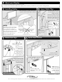
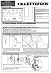
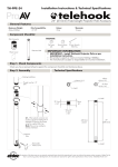
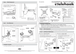
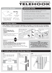
Installation Instructions
TELEHOOK
Cable Manager
IMPORTANT NOTES
It is recommended that your display be installed prior to the installation of this product.
If you wish to paint your Cable Manager, please consult your paint specialist for advice.
Surface finish: Clear Anodised Aluminium
Component Checklist
(Check you have received all parts against the Component Checklist below)
Bits Box
Front Fascia
End Profile
10g x 30mm
Screw (x4)
Wall Plate
Cable Tabs (x8)
End Profile
End Cap (x2)
Tools Required:
A
M4 x 5mm Grub
Screw (x4)
Nylon Wall
Plug (x4)
z
Power drill
z
4mm ( 3/16”) drill bit
z
6mm ( 1/4”) drill bit
z
2mm Allen Key
Dry Wall
Anchor (x6)
Phillips head screwdriver
Mount the Wall Plate
Timber Stud Wall
Dry Wall
Masonry
Timber Stud
Wall Plate
Nylon Wall Plug
OR
OR
6mm
(1/4”)
hole
Masonry
Wall
Mounting
Hole
Pattern
Dry Wall Anchor
Screw
10g x 30mm
screw
10g x 30mm
screw
4mm (3/16”)
hole
Dry Wall
6mm
(1/4”)
hole
Mounting
Hole
Pattern
Dry
Wall
Anchor
Mounting
Hole
Pattern
To determine the best position for your Cable Manager, see “Mounting Tips” below
IMPORTANT: Ensure the lower edge of the Wall Plate is positioned no less than 50mm
(2”) above the skirting board so that there is enough room to accommodate the End Cap
IMPORTANT: For Dry Wall Installation
use alternating mounting holes
Mounting Tips:
Display
Telehook Cable Manager has been designed to hide the cables of a wall mounted display.
Therefore, it is recommended that it is mounted vertically and centrally below your display.
The adjoining image shows a typical Cable Manager installation.
Ideally, the top of Telehook Cable Manager should sit just under the lower edge of your display
with the bottom of Telehook Cable Manager (i.e. the End Cap) sitting approximately 50mm (2")
above the floor or skirting board.
Telehook
Cable
Manager
Optional Shelf
(sold separately)
End Cap
TM
B
z
z
C
Mount your Display
Mount your display onto its wall mount bracket
Connect all the required cables to the display and if necessary, manoeuvre it into its final viewing position
D
Installing Cables
Insert Cable Clips
Install the display’s cables into the left,
right and centre cable bays as shown
Cable
Tab
Display on
wall mount
bracket
If required, cables can exit
from the side of the Cable
Manager. In this case, use
the left or right cable bays
only.
Cables exiting from the side
E.1.
Using your
thumb and
index finger,
flex the Cable
Tab into a
concave shape
Wall Plate
NOTE:
Data cables
If possible, separate the display’s
Display Power
cable
(can also be installed
into the same bay)
power cable from the data cables
TOP VIEW
(i.e. hi-fi & speaker cables) by
installing them into separate cable
bays. This will reduce the chance of
electromagnetic interference. The
Left cable bay
Right cable bay
diagram to the right shows an
Centre cable bay
example installation setup.
(best for display power cable)
E
Insert the Cable Tabs into
the Wall Plate to Secure
Cables in place.
Attach End Caps
F
E.2.
Twist the Cable
Tabs into the small
slots in the Wall
Plate
Insert Front Fascia
End Cap Cable Bay
TOP VIEW
A
TOP VIEW
Using two hands,
flex the End Cap
around the
display’s cables
and manoeuvre
them into their
corresponding End
Cap Cable Bay
B
Front Fascia
F.1.
Partially insert the
front facia as shown
Attach an End Cap onto
both ends of the Wall
Plate and secure in place
using the M4 Grub
Screws as shown.
M4
Grub
Screw
WARNING: DO
NOT OVER TIGHTEN
2mm
Allen
Key
F.2.
Push the edge of the
Front Facia until it snaps
into place
F.3. Repeat F.2.
down the length
of the Front Facia
until it is firmly
secured onto the
Wall Plate
Installation Complete
Due to continuing product development, the manufacturer reserves the right to alter specifications without notice. Published: 08.03.07©