1
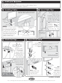
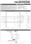
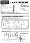
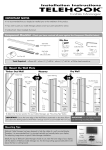
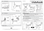
Installation Instructions
TELEHOOK
TM
Cable Manager Shelf System
IMPORTANT NOTES
Component Checklist
The Telehook Cable Manager Shelf System MUST be used in
conjunction with the Telehook Cable Manager.
Bits Bag
Each Telehook Cable Manager is limited to a maximum of 4 Shelves.
Shelf (x2)
M4 x 5mm Grub
Screw (x8)
Check you have received
all parts against the
Component Checklist
A
2mm Allen Key
Each Shelf supports a maximum weight of 20kgs (44lbs).
If you wish to paint your Cable Manager Shelves, please consult your
paint specialist for advice.
Installation Options
If your display is already wall mounted, depending on its position, it may be best to remove the display,
as it may interfere with the installation of the Telehook Cable Manager and Cable Manager Shelf System.
Option 1
If you already have the
Telehook Cable Manager
installed.
Begin by removing the Front Fascia and
the End Caps as shown. Once
complete, continue to step B below.
Remove End
Caps
Push one edge of the
Front Fascia until it
pops open
OR
Option 2
If you are installing both
the Telehook Cable Manager and Telehook Cable
Manager Shelf System at the same time.
Begin by mounting the Wall Plate as shown in step A on the
Telehook Cable Manager Installation Instructions. Once complete,
continue to step B below.
B
Note:
If the mounted height of the display is
less than the length of the Telehook
Cable Manager, you may need to reduce
the length by cutting it to size.
(Consult a professional at this stage)
Installing Telehook Cable Manager Shelves
B.1.
Slide the Cable Manager Shelf
onto the Cable Manager Wall
Mount
TOP VIEW
B.2.
Adjust the Cable Manager
Shelf to the
desired height
B.3.
Secure in place using the M4 Grub Screws and
the 2mm Allen Key supplied
C
Install your Equipment
Install or reinstall your display
Place your Audio/Video equipment on the Telehook Cable Manager Shelves
Connect all required cables to Audio/Video equipment
D
E
Installing Cables
Insert Cable Clips
Install the display’s cables into the left,
right and centre cable bays as shown
Cable
Tab
Display on
wall mount
bracket
If required, cables can exit
from the side of the Cable
Manager. In this case, use
the left or right cable bays
only.
Cables exiting from the side
Wall Plate
E.1.
Using your
thumb and
index finger,
flex the Cable
Tab into a
concave shape
Shelf
Data cables
NOTE:
If possible, separate the display’s
power cable from the data cables
(i.e. hi-fi & speaker cables) by
installing them into separate cable
bays. This will reduce the chance of
electromagnetic interference. The
diagram to the right shows an
example installation setup.
F
Insert the Cable Tabs into
the Wall Plate to Secure
Cables in place.
Display Power
cable
(can also be installed
into the same bay)
TOP VIEW
Left cable bay
Right cable bay
Centre cable bay
E.2.
Twist the Cable
Tabs into the small
slots in the Wall
Plate
(best for display power cable)
Attach End Caps
End Cap Cable Bay
TOP VIEW
G
Insert Front Fascia
G.1.
Slide the Front
Fascia through the
cut outs in the
Shelves
Using two hands,
flex the End Cap
around the
display’s cables
and manoeuvre
them into their
corresponding End
Cap Cable Bay
TOP VIEW
A
B
G.2.
Partially insert the front
fascia as shown above
Attach an End Cap onto
both ends of the Wall
Plate and secure in place
using the M4 Grub
Screws as shown.
M4
Grub
Screw
WARNING: DO
NOT OVER TIGHTEN
2mm
Allen
Key
G.3.
Push the edge of the
Front Fascia until it
snaps into place
G.4.
Repeat G.3.
down the
length of the
Front Fascia
until it is firmly
secured onto
the Wall Plate
Installation Complete
Due to continuing product development, the manufacturer reserves the right to alter specifications without notice. Published: 24.09.07©