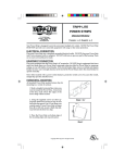
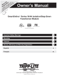
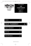
1
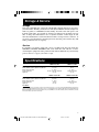
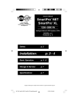
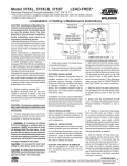
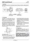
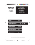
Owner's Manual
SmartPro NET
SmartPro XL
®
®
1111 W. 35th Street
Chicago, IL 60609 USA
Customer Support: (773) 869-1234
www.tripplite.com
1250–3000 VA
Intelligent Network UPS Systems (120V)
ESPAÑOL: p. 8
FRANÇAIS: p. 15
Safety:
p. 2
Installation:
p. 3 - 4
Basic Operation:
p. 4 - 6
Storage & Service:
p. 7
Specifications:
p. 7
Warranty & Insurance:
p. 6
Copyright © 1999 Tripp Lite. All rights reserved. SmartPro® is a registered trademark of Tripp Lite.
1
9811198 SmartPro NET & SmartPro XC Owners
1 Manual.p65
5/17/00, 10:56 AM
Important Safety Instructions
SAVE THESE INSTRUCTIONS
This manual contains important instructions and warnings that should
be followed during the installation, operation and storage of all Tripp Lite UPS
systems. Failure to follow these warnings will void your warranty.
UPS Location Warnings
• Install your UPS indoors, away from excess moisture or heat, conductive
contaminants, dust or direct sunlight.
• For best performance, keep the indoor temperature between 32° F and
104° F (between 0° C and 40° C).
• Leave adequate space around all sides of the UPS for proper ventilation.
UPS Connection Warnings
• Connect your UPS directly to a properly grounded AC power outlet.
Do not plug the UPS into itself; this will damage the UPS.
• Do not modify the UPS’s plug, and do not use an adapter that would
eliminate the UPS’s ground connection.
• Do not use extension cords between the UPS and outlet. Your warranty will
be voided if anything other than Tripp Lite surge suppressors are used to
connect your UPS to an outlet.
• If the UPS receives power from a motor-powered AC generator, the generator
must provide clean, filtered, computer-grade output.
Equipment Connection Warning
• Do not use Tripp Lite UPS Systems for life support appliances in which a
malfunction or failure of a Tripp Lite UPS System could cause failure or
significantly alter the performance of a life-support device.
• Do not connect surge suppressors or extension cords to the output of your
UPS. This might damage your UPS and will void both the surge suppressor
and UPS warranties.
Battery Warnings
• Your UPS does not require routine maintenance. Do not open your UPS
except to replace batteries. There are no user-serviceable parts inside.
• Battery replacement should be performed by qualified service personnel.
Because the batteries present a risk of electrical shock and burn from high
short-circuit current, service personnel should observe proper precautions.
Use tools with insulated handles, remove all metal hand jewelry and when
possible work with only one hand to reduce the danger of shock. Replace the
existing batteries with an equal number of new batteries of the same type.
Do not open the sealed lead-acid batteries. Do not short or bridge the battery
terminals with any object.
• The UPS batteries are recyclable. Refer to local codes for disposal requirements or in the USA only call 1-800-SAV-LEAD (1-800-728-5323) for
complete recycling information. Do not dispose of the batteries in a fire.
• The UPS contains its own energy source (battery). The output terminals may
be live even when the UPS is not connected to an AC supply.
• Only connect Tripp Lite battery packs of the correct voltage to your UPS’s
external battery connectors.
• Do not connect or disconnect external battery packs while the UPS is
operating from battery.
• Do not operate your UPS without batteries.
Installation
1
Plug your UPS into
an electrical outlet.
See “Suggested Circuit” in Specifications section
to determine if your model should occupy a 20or 30-amp dedicated circuit.
2
Plug your equipment
into your UPS.
Your UPS is designed to support
only computer equipment.
Connecting household appliances,
laser printers or surge suppressors
is not recommended.
3
Turn your UPS ON.
· Set the System Enable Switch (DIP
Switch #4, UPS back panel) to the
“ENABLE” (UP) position.
(See Figure 1)
This switch activates the battery charger and
microprocessor.
Figure 1
DIP Switch #4
(System Enable Switch)
ENABLE
DISABLE
The “XXX” light will flash until you engage the
ON/Standby Switch to activate the “ON” mode.
· Engage the momentary ON/Standby
Switch (UPS front panel) and release it
to activate the “ON” mode and supply
power to the UPS receptacles.
Figure 2 - ON/Standby Switch
(See Figure 2)
DB9 Port Connection (Optional) On Next Page . . .
3
9811198 SmartPro NET & SmartPro XC Owners
3 Manual.p65
5/17/00, 10:56 AM
DB9 Port Connection
–Optional–*
1
Using Tripp Lite cable, connect your
primary server’s DB9 port to the single
DB9 port labeled “SMART” (which
provides complete intelligent RS-232
communications).**
2
If you have additional
computers:
a. Connect them to the DB9 ports
labeled “BASIC” (which provide basic,
contact-closure shutdown capabilities).
b. Set their corresponding LAN Interface
DIP Switches to the ACTIVATE
(DOWN) position. See diagram for
which switch controls which port.***
2a. Back Panel
DIP Switches #2 & #1
(Lan Interface Switches)
DEACTIVATE
ACTIVATE
2b. Back Panel
3
Load software and run the installation program
appropriate for your operating system.
* Serial port connections are optional. Your UPS will function properly without these connections.
** The “SMART” DB9 port is always enabled and is not controlled by the LAN Interface DIP Switches.
*** If you do not connect a computer to either of the “BASIC” DB9 ports, set their corresponding LAN Interface DIP
Switches to the DEACTIVATE (UP) position. Note: DIP Switch #3 has no function.
Basic Operation
Switches
System Enable Switch (DIP Switch #4)
This switch is located in the set of 4 switches next to the UPS’s DB9
ports. It activates the battery charger and intelligent microprocessor. Always leave it in the “ENABLE” (UP) position when your UPS
is plugged in. Set the switch to “DISABLE” (DOWN) only if you store
or ship your UPS (to reduce battery drain).
Note: the “XXX” light will flash until you engage the ON/Standby Switch to activate the “ON”
mode (power ON at the UPS receptacles).
4
9811198 SmartPro NET & SmartPro XC Owners
4 Manual.p65
5/17/00, 10:57 AM
ON/Standby Switch
This momentary switch controls power to the UPS receptacles.
Engage it momentarily and release it to toggle between the “ON”
mode (power ON at the UPS receptacles) and “Standby” mode
(power OFF at the UPS receptacles).
Mute/Test Switch
Use this momentary switch to do two things:
Silence the blackout alarm
Engage this switch and release it. Note: when the battery is nearly
depleted, the alarm resumes (and cannot be silenced) to alert you
to immediately shut down connected equipment.
Test your UPS’s battery charge
Leave your connected equipment ON. With your UPS plugged in
and completely turned ON, engage this switch; hold it there for 5
seconds and release it. The UPS will momentarily switch to battery
to test its charge. The “XXX” light will turn ON and the alarm may
sound if your UPS fails a self-test and/or the UPS battery is less
than fully charged. Let the UPS charge for 12 hours and perform
a second self-test. If the light continues to stay on, contact Tripp
Lite for service. CAUTION: Do not unplug your UPS to test its
batteries. This will remove safe electrical grounding and may
introduce a damaging surge into your network connections.
Indicator Lights
All Indicator Light descriptions apply when the UPS is plugged into a wall outlet
and turned ON.
This green light will shine constantly to indicate AC power is
available at the receptacles. It will flash to indicate AC power is not
available. (See “System Enable Switch” and “ON/Standby Switch”
descriptions above.)
This multi-colored light displays 7 separate UPS battery charge
conditions. It will turn from red (low) to yellow (medium) to green
(full) to show you the level of battery charge. If the light is constant,
then your UPS is operating from line power and the battery is
charging. If the light is flashing, then your UPS is operating from
battery power and the battery is discharging. When the light
flashes red, close any files you are working on and shut down your
computer.
Whenever your UPS is automatically correcting high or low AC line
voltage, this green light will turn ON and the UPS will gently click.
The more the UPS has to correct voltage, the more the green light
will turn ON and the more the UPS will click. These are both
normal, automatic operations of your UPS, and no action is
required on your part.
This red light will turn ON if your UPS fails a self-test and/or the
UPS battery is less than fully charged. Let the UPS charge for 12
hours and perform a second self-test. If the light continues to stay
on, contact Tripp Lite for service.
5
9811198 SmartPro NET & SmartPro XC Owners
5 Manual.p65
5/17/00, 10:57 AM
This multi-colored light displays 4 separate UPS load conditions.
It will turn from green (low) to yellow (medium) to red (high) as you
connect equipment to show you the load level your UPS is supporting. When the light is red your UPS is supporting a load above 85%
of its capacity. If the red light begins flashing, your UPS is severely
overloaded. Remove overload immediately until light stops flashing.
Other UPS Features
AC Receptacles
The receptacles provide your connected equipment with AC line
power during normal operation and battery power during blackouts and brownouts. They also protect your equipment against
damaging surges and line noise. You can remotely reboot connected equipment by turning all of the receptacles OFF and ON at
once using Tripp Lite UPS software. Select models, however,
feature unique “Remote Reboot Outlets” (identified on the back
panel of your UPS) which allow you to use Tripp Lite UPS software
to remotely reboot equipment connected to these outlets without
interrupting power to equipment connected to the other outlets.* See
software instructions for details.
* Note: constant power is available at the Remote Reboot Outlets (and all other outlets)
unless controlled through Tripp Lite UPS software.
“SMART” RS-232 Port
The RS-232 port connects your UPS to any workstation or server.
Use with Tripp Lite software and #73-0743 cable to monitor and
manage network power and automatically save open files and shut
down equipment during a blackout. This port uses RS-232 communications to transmit UPS and power conditions (Pin 7 =
Transmit; Pin 8 = Common; Pin 9 = Receive). Contact Tripp Lite
Customer Support for more information and a list of available
SNMP, network management and connectivity products.
“BASIC” Contact-Closure Ports
The contact-closure ports connect your UPS to any workstation or
server. Use with Tripp Lite software and #73-0724 cabling to
automatically save open files and shut down equipment during a
blackout. This port sends contact-closure signals to indicate linefail and low-battery status. Contact Tripp Lite Customer Support
for more information.
External Battery Connector (available on select models)
Use this to connect additional Tripp Lite battery packs for additional runtime. Refer to the label next to the connector for
appropriate Tripp Lite battery pack to connect. Refer to instructions available with the battery pack for complete connection
information and safety warnings.
LAN Interface DIP Switches
DIP Switches #1 and #2 activate or deactivate remote shutdown
through the “BASIC” Contact-Closure Ports. See “DB9 Port Connection” on page 4 for which switch controls which port. Note: DIP
Switch #3 has no function. DIP Switch #4 serves as
the UPS’s “System Enable Switch.”
6
9811198 SmartPro NET & SmartPro XC Owners
6 Manual.p65
5/17/00, 10:57 AM
Storage & Service
Storage
Turn your UPS OFF: first, engage the ON/Standby Switch and release it to place
your UPS in the “Standby” mode; then set the System Enable Switch (Jumper #4,
UPS rear panel) to “DISABLE” (Down); finally, disconnect the UPS power cord
from the wall outlet. If you plan on storing your UPS for an extended period of
time, recharge the UPS batteries once every three months. Follow steps #1 and
#3 in the Installation section and allow the UPS to charge from 4 to 6 hours. If
you leave your UPS batteries discharged for an extended period of time, they will
suffer permanent loss of capacity.
Service
If returning your UPS to Tripp Lite, please carefully pack the UPS using the
ORIGINAL PACKING MATERIAL that came with the unit. Enclose a letter
describing the symptoms of the problem. If the UPS is within the 2 year warranty
period, enclose a copy of your sales receipt.
Specifications
SMART 2200 NET
SMART 3000 NET
Output Capacity (VA/Watts):
2200/1700
Battery Runtime (Half Load/Full Load) Minutes:
27+/11+
Battery Recharge Rate:
2 - 4 hrs.
Suggested Circuit:
15-amp or 20-amp dedicated
Approvals:
UL, cUL
Output Capacity (VA/Watts):
Battery Runtime (Half Load/Full Load) Minutes:
Battery Recharge Rate:
Suggested Circuit:
Approvals:
3000/2400
23+/7+
2 - 4 hrs.
30-amp dedicated
UL, cUL
SMART 1250XL NET
SMART 2200XL NET
1250/900
85+/24+
2 - 4 hrs.
15-amp
UL, cUL
2200/1750
28+/11+
2 - 4 hrs.
20-amp dedicated
UL, cUL
ALL MODELS:
Input Voltage/Frequency (120V/60 Hz); On Line Input Voltage Range (87 - 140 volts); Voltage-Regulated Output Voltage Range
(120V +/- 9%); On Battery Output Voltage Range (120V +/- 5%); Output Waveform Line Mode (filtered sinewave); Output Waveform
Battery Mode (PWM sine wave); AC Surge Suppression (exceeds IEEE 587 Cat. A & B standards); AC Noise Attenuation (>40 dB);
AC Protection Modes (H to N, H to G, N to G).
7
9811198 SmartPro NET & SmartPro XC Owners
7 Manual.p65
5/17/00, 10:57 AM
1111 W. 35th Street, Chicago, IL 60609 USA
773.869.1234 (USA) • 773.869.1212 (International)
www.tripplite.com
2009XXXXX 93-1310_EN