1
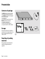
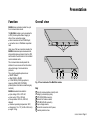
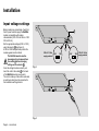
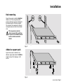
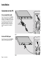
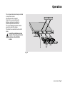
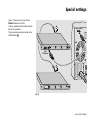
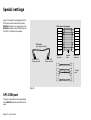
Contents
Presentation
Contents of package ......................................................................................... 2
Storage ............................................................................................................. 2
Recycling of packing materials ......................................................................... 2
Function ............................................................................................................ 3
Overall view ...................................................................................................... 3
Installation
Input voltage settings ........................................................................................ 4
Installation ......................................................................................................... 5
Connection to the UPS ..................................................................................... 6
Operation .............................................................................................................. 7
Special settings
Installation of a second module ........................................................................ 8
UPS COM port ................................................................................................ 10
Troubleshooting
Operating anomalies ....................................................................................... 11
Fuse replacement ........................................................................................... 11
Appendices
Glossary .......................................................................................................... 12
Index ............................................................................................................... 12
All MGE UPS SYSTEMS products are protected by patents. They implement original technology which is not available to other
competitors of MGE UPS SYSTEMS.
To take evolving standards and technology into account, the technical characteristics contained in this document are not
binding unless confirmed by MGE UPS SYSTEMS.
This document may be reproduced only with the consent of MGE UPS SYSTEMS. Authorised copies must be marked
"MGE UPS SYSTEMS extension module for communication cards installation and user manual n° 5102919700".
51029197EN/BB
- Page 1
Presentation
Contents of package
The MultiSlot optional module is made up
of the following components (see figure 1):
◗ the MultiSlot module itself (not equipped
with the optional cards);
◗ one power cord;
◗ one installation and user manual for the
MultiSlot module (this document);
◗ four adhesive support pads;
◗ two M6 screws and two cage nuts;
◗ one spare fuse (500 mA, 250V, delayed).
www.mgeups.com
MGE UPS SYSTEMS
Multislot
Extension module
for
communication
cards
Installation and user
manual
Storage
MGE
If the module is stored prior to installation, it
should remain in the original packing in a dry
place. The storage temperature range is
–40°C to +70°C.
Recycling of packing
materials
Packing materials must be disposed of in
compliance with applicable laws and
regulations.
Page 2 - 51029197EN/BB
UPS SYSTEMS
THE UNINTERRUPTIBLE POWER PROVIDER
Fig. 1
Presentation
Function
MultiSlot is an extension module for up to
four communications cards.
The MultiSlot module may be connected to
a UPS (Uninterruptible Power Supply) in
either of two connection modes:
◗ direct connection to the UPS BUS port;
◗ connection via a U-Talk/Basic acquisition
card.
Using one of the two connection modes, the
MultiSlot module acquires measurements,
status information and alarms from the UPS
and transmits the information to the installed
communications cards.
The communications cards provide the
interface for user access to the information
via a wide range of communications
protocols.
The currently available protocols are:
◗ SNMP 10BaseT;
◗ JBus RS232 or RS485;
◗ U-Talk RS232 (ASCII-type protocol,
property of MGE UPS SYSTEMS);
◗ Basic (status information coded using dry
contacts).
MultiSlot-module characteristics:
◗ input voltage: 230 or 120V AC;
◗ input current: 150 or 300 mA;
◗ fuse protection: 500 mA, 250V AC,
delayed;
◗ maximum operating temperature: 35°C;
◗ dimensions: 1 U x 19" (44.45 x 482.6 mm);
◗ weight: 2.8 kg.
Overall view
1
UPS
COM
2
UPS
BUS
3
4
5
6
7
Fig. 2: Front and back of the MultiSlot module.
Key
1 slots for communications cards (4 slots
including 3 protected by a plate),
2 UPS COM (DB9 connector),
3 selector for module number,
4 UPS BUS (RJ45 connector),
5 input voltage selector,
6 socket for connection to AC power,
7 module protection fuse.
51029197EN/BB
- Page 3
Installation
Input voltage settings
Before making any connections, check that
the AC power used to supply the MultiSlot
module is compatible with module
characteristics (230V 150 mA 50Hz or 120V
300 mA 60 Hz).
Set the appropriate voltage (230V or 120V)
using the selector 5 (see figure 3).
A 500 mA 250V delayed fuse protects the
module against electrical faults.
The MultiSlot module must be
deenergized (cord removed from
the socket 6 before changing
settings on the selector 5 ).
Once the voltage has been correctly set,
insert the cord in the socket 6 at the back
of the MultiSlot module (see figure 4).
The cord is made up of two active wires and
an earth wire which must be connected to
the installation earthing terminal.
6
UPS
COM
5
230V AC / 50Hz
supply selected
230V
120V
120V AC / 60Hz
120V supply selected
230V
Fig. 3
6
UPS
COM
Fig. 4
Page 4 - 51029197EN/BB
UPS
BUS
UPS
BUS
Installation
Rack mounting
Figure 5 shows how to install the MultiSlot
module in a 19" rack using the two M6
screws and the two cage nuts positioned at
the desired height on the frame uprights.
The module is not as wide as the rack and
consequently does not block the circulation
of air.
If the temperature inside the
cabinet exceeds 35°C, ventilation
is required or the MultiSlot module
must be installed outside the
cabinet.
Fig. 5
Adhesive support pads
Figure 6 shows how to attach the four
adhesive support pads under the MultiSlot
module to keep it from slipping on a flat
surface.
Fig. 6
51029197EN/BB
- Page 5
Installation
Connection to the UPS
U-Talk or Basic
Via an acquisition card
Figure 7 shows connection of the MultiSlot
module to a UPS using an acquisition card
intended for a U-Talk/Basic communications
port. Consult the user manual of the card
concerning configuration in the U-Talk or
Basic modes. The cable for connection to
the UPS is supplied with the acquisition
card.
UPS
U-Talk / Basic
1
Fig. 7
Via the UPS BUS port
Figure 8 shows connection of the MultiSlot
module to a UPS using an RJ45 cable.
UPS BUS
UPS
COM
UPS
BUS
4
Fig. 8
Page 6 - 51029197EN/BB
Operation
The communications cards may be installed
in any of the four slots.
No particular order is required.
Figure 9 shows one possible order.
Before a card may be installed, the
protection plate must be removed.
The screws holding the plate are used to
secure the card in the module.
The plates for unused slots must be left in
place.
Consult the installation and user
manuals of the cards prior to their
installation in the MultiSlot
module.
UPS
U-Talk/Basic
SNMP
10BT
JBUS
Fig. 9
51029197EN/BB
- Page 7
Special settings
Installation of a
second module
Depending on the surveillance needs for the
installation, it may be useful to increase the
number of connection points by installing a
second MultiSlot module.
Figure 10 shows the parameter settings for
each of the two modules.
Installation of a second MultiSlot module is
possible only for UPSs equipped with a UTalk or Basic communications port.
UPS
COM
3
Setting for unit
MultiSlot 1
Fig. 10
Page 8 - 51029197EN/BB
UPS
BUS
OFF
1
OFF
8
ON
1
8
ON
Setting for unit
MultiSlot 2
Special settings
Figure 11 shows how to connect the two
MultiSlot modules to the UPS.
Only one acquisition card should be used for
the set of two modules.
The two modules are interconnected via the
UPS BUS ports 4 .
4
U-Talk or Basic
OUT
UPS
U-Talk/Basic
4
1
10A/250V
2
Ue/In/Eing
Fig. 11
51029197EN/BB
- Page 9
Special settings
Figure 12 shows the wiring diagram for the
RJ45 cable used to interconnect the two
MultiSlot modules or to connect one of the
MultiSlot modules to the UPS BUS port on
the UPS. The cable is not supplied.
RJ45-cable wiring diagram
1
2
3
4
5
6
7
8
RJ45 cable
(max. length 5 meters)
1
2
3
4
5
6
7
8
body
male RJ45
connector
shielded RJ45
8-wire connector
Fig. 12
UPS COM port
This port is reserved for future applications
of the MultiSlot module and should not be
used.
Page 10 - 51029197EN/BB
shielded RJ45
8-wire connector
1
2
3
4
5
6
7
8
body
shielded
cable
male RJ45
connector
1
2
3
4
5
6
7
8
4 twisted
pairs
Troubleshooting
Operating anomalies
Fuse replacement
AC-power problem
Card start-up problem
The green lights on the communications
cards and the acquisition card are all off:
◗ check the position of the input voltage
selector (see figure 3),
◗ check that the power cable is properly
connected (see figure 4),
◗ check the fuse and replace it if necessary
(see below "fuse replacement").
The green light on a communications card
remains on or off:
◗ check that the card is correctly installed in
the MultiSlot module,
◗ press the reset button of the faulty card.
Communications problem
The green lights on the communications
cards flash regularly every second for more
than one minute:
◗ check the connection between the
MultiSlot module and the UPS (see figures
7, 8 and 11),
◗ check that the cards are correctly installed
in the MultiSlot module,
◗ press the reset button on each card
installed in the MultiSlot module,
◗ if necessary, deenergize and reenergize
the MultiSlot module.
The MultiSlot module is protected by a fuse.
If the fuse blows, it must be replaced, as
shown in figure 13.
The replacement fuse must imperatively
have the same characteristics as the original
fuse (500 mA, 250V, delayed).
A replacement fuse is supplied with the
MultiSlot module.
Invalid installation
configurations
7
The following installation configurations are
invalid:
◗ MultiSlot module not connected to a UPS
(no U-Talk/Basic acquisition card or no
direct connection via the UPS BUS port),
◗ MultiSlot module equipped with two UTalk/Basic acquisition cards,
◗ installation in duo mode (two modules)
with an acquisition card in each MultiSlot
module,
◗ MultiSlot module equipped with both a UTalk/Basic acquisition card and a connection
to a UPS via the UPS BUS port.
Fig. 13
If the problem continues, contact our
after-sales support department.
51029197EN/BB
- Page 11
Appendices
Glossary
Index
Basic: information exchange protocol using
dry contacts,
AC power ............................................................................................................................. 4, 11
I2C: multi-point and multi-master
communications protocol and bus,
JBus: master-slave communications
protocol using a point-to-point (RS232) or
multi-point (RS485) serial link,
SNMP: Ethernet communications protocol,
UPS: Uninterruptible Power Supply,
U-Talk: point-to-point ASCII
communications protocol using an RS232
serial link. U-Talk is the MGE UPS
SYSTEMS proprietary protocol.
Acquisition card .............................................................................................................. 6, 9, 11
Acquisition cable .................................................................................................................. 6, 9
Adhesive support pads ........................................................................................................ 2, 5
Characteristics .......................................................................................................................... 3
Communications card ........................................................................................................ 7, 11
Contents of package ................................................................................................................. 2
Fuse .................................................................................................................................. 2, 4, 11
I2C RJ45 cable ................................................................................................................. 6, 9, 10
Power cord ............................................................................................................................ 2, 4
Protection plates ................................................................................................................... 2, 7
Rack ....................................................................................................................................... 2, 5
Second MultiSlot module ...................................................................................................... 8-9
Settings .................................................................................................................................. 4, 8
Troubleshooting ...................................................................................................................... 11
UPS (connection) ............................................................................................................ 6, 9, 11
Warnings (
Page 12 - 51029197EN/BB
) ............................................................................................................... i, 4-5, 7