1
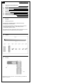
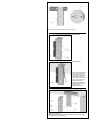
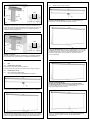
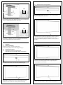
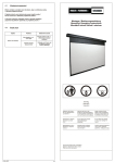
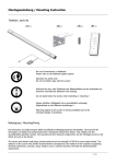
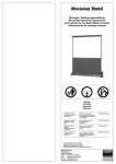
Rollux 2
Montage-/ Bedienungsanleitung
Mounting/ Operating instructions
Instructions de montage/ Mode d´emploi
Instrucciones de montaje/ manejo
kg
Wichtig
Attention
Important
Atención
Gefährlich für Kinder !
Nur von Erwachsenen
zu bedienen !
Während des Aus- oder
Einfahrens der Bildwandfläche
ist der Aufenthalt von Personen
nicht zulässig !
Wegen erhöhter Unfallgefahr ist es grundsätzlich
untersagt, Gegenstände an
der Bildwand anzubringen !
Hazardous to children !
Operation by adults
only !
Do not stand near screen
when extending or
retracting !
Do not attach any objects
on the screen (danger of
injury) !
Dangereux pour les
enfants !
Utilisation pour adultes
seulement !
Ne pas se tenir à proximité
lors du mouvement de
l´écran !
Le fabricant interdit de fixer
des objets quelconques sur
l´écran (risque d´accident) !
Peligroso para niños !
Solo usable para
adultos !
No se permite la estancia de
personas durante el ascenso
o descenso de la pantalla de
proyección !
Evite fijar objetos en la pantalla, pues podría provocar
algún accidente !
Technische Änderungen vorbehalten.
Subject to alterations without notice.
Modifications techniques sous réserve.
Nos reservamos el derecho a realizar modificaciones.
MEDIUM GmbH
Willstätterstr. 7
40549 Düsseldorf
Telefon: +49 (0) 211-52 76-0
Fax:
+49 (0) 211-52 76-100
E-mail: [email protected]
Internet: www.medium.de
MEDIUM
DÜSSELDORF * ZÜRICH * WIEN
LONDON * MAILAND
The Conference Company
D
Inhaltsverzeichnis
1.
Allgemeine Sicherheitshinweise
1
2.
2.1
2.2
2.3
Montage
Befestigungshinweise
Teileliste
Montage
2
2
2
2
3.
3.1
3.2
3.3
3.4
Bedienung
Allgemeine Hinweise
Bedienungsanleitung
Bedienung bei Wandmontage
Bedienung bei Deckenmontage
4
4
4
4
5
2.
Montage
2.1
Befestigungshinweise
- Die Schrauben und Dübel müssen 1000N Ausreißkraft je
Befestigungswinkel standhalten.
- Die Auswahl der Schrauben und Dübel muß entsprechend dem
Untergrund (Mauerwerk, Beton, Holz, Metall) und dem
Ausreißkräften getroffen werden.
- Die Auswahl soll dem vorgehenden Anspruch entsprechen,bei der
Montage sowohl an die Wand als auch an die Decke.
2.2
Teileliste
(1) 1x
(2) 1x
2.3
(3) 1x
(4) 2x
(5) 2x
(6) 4x
(7) 2x
(8) 2x
Montage
(1)
(2)
Neigewinkel (2) mit den Laschen in die Tubenhalterung des Bildwandkastens (1) schieben.
2
(7)
(2)
Neigewinkel (2) mit zwei Blechschrauben (7) sichern.
Wandmontage
(3)
Deckenmontage
Wand- und Deckenhalterung
(3) in gewünschter Position
an die Wand oder an die
Decke halten, mit Hilfe einer
Wasserwaage regulieren
und die Bohrlöcher markieren.
(3)
Löcher (für die Wand- und
Deckenhalterung) der
Markierung entsprechend
bohren und Dübel einsetzen.
(Siehe hierzu: 2.1
Befestigungshinweise)
(1)
(a)
(2)
(3)
(b)
(b)
Bildwandkasten (1) mit Neigewinkel (2) auf Wand- und Deckenhalter (3)
schieben und festhalten.
Wichtig: Neigungsschnäpper (a) einrasten lassen ! Achten Sie darauf, daß die
Bohrungen (b) übereinander liegen !
3
3.4
Uso en caso de montaje en el techo
(1)
(8)
(8)
(4)
(5) (6)
(2)
(6) (5)
(4)
Abrir la superficie de proyección: Estire del mango situado en la superficie
de proyección (a) hacia abajo, hasta que note cómo encajan los elementos.
(4) (5) (6) (2)
(3)
(6) (5) (4)
Wandmontage: Mit Hilfe von Schrauben (4), Scheiben (5) und Tellerscheiben
(6) Wand- und Deckenhalter (3) mit Neigewinkel (2) sichern.
Zwei Blechschrauben (8) als zusätzliche Sicherung anbringen, da die Bildwand
(1) bei Wandmontage nicht zum Neigen ausgelegt ist.
(1)
(2)
(5) (6)
(6) (5)
(4)
(4)
(3)
(4) (5) (6) (2)
Inclinar la superficie de proyección: Sólo se puede inclinar la pantalla
cuando está completamente abierta. Empuje la superficie de proyección
por el mango (a) hacia atrás, pasando por el punto en el que ofrece
resistencia, hasta que la pantalla se incline. La inclinación sin
escalonamiento se puede ajustar posteriormente mediante tornillos (4)
(véase también 2.3 Montaje).
(6) (5) (4)
Deckenmontage:
Mit Hilfe von Schrauben (4), Scheiben (5) und Tellerscheiben (6)
Wand- und Deckenhalter (3) mit Neigewinkel (2) sichern.
3.
Bedienung
3.1
Allgemeine Hinweise
Gefährlich für Kinder ! Nur von Erwachsenen zu bedienen !
Wegen erhöhter Unfallgefahr ist es grundsätzlich untersagt, Gegenstände
an der Bildwand anzubringen !
3.2
3.3
Bedienungsanleitung
Bedienung bei Wandmontage
Bei Wandmontage ist eine Neigung der Bildwandfläche nicht möglich!
Cerrar la superficie de proyección:
Sólo se puede cerrar la superficie de proyección en posición vertical
(posición 0°). Tire del mango situado en la superficie de proyección (a)
desde la posición inclinada hacia delante, hasta que llegue a la posición
de 0° y note que los pestillos de inclinación encajan.
Ausfahren der Bildwandfläche: Ziehen Sie die Bildwandfläche am
Griff (a) nach unten, bis die Gelenke spürbar einrasten.
(a)
Empuje el mango situado en la superficie de proyección (a) hacia arriba,
pasando por el punto en el que ofrece resistencia. A partir de una posición
determinada la pantalla se enrolla automáticamente.
Einfahren der Bildwandfläche: Ziehen Sie die Bildwandfläche am
Griff (a) über den Widerstandspunkt nach oben. Ab einer gewissen
Position rollt die Bildwandfläche automatisch ein.
4
17
3.4
Bedienung bei Deckenmontage
(1)
(8)
(8)
(4)
(5) (6)
(2)
(6) (5)
(4)
(4) (5) (6) (2)
(3)
Ausfahren der Bildwandfläche: Ziehen Sie die Bildwandfläche am
Griff (a) nach unten, bis die Gelenke spürbar einrasten.
(6) (5) (4)
Montaje en pared: Asegurar, mediante tornillos (4), arandelas (5) y arandelas
de platillo (6), el soporte mural y de techo (3) con el ángulo de inclinación (2).
Montar dos tornillos para chapa adicionales (8) para conseguir una fijación más
segura, puesto que la pantalla de proyección (1) no está diseñada para ser
inclinada en caso de montaje mural.
(1)
(2)
(5) (6)
(6) (5)
(4)
(4)
(3)
(4) (5) (6) (2)
Neigen der Bildwandfläche: Neigung der Bildwandfläche nur in komplett
ausgefahrener Position! Drücken Sie die Bildwandfläche am Griff (a) über
den Widerstandspunkt nach hinten, bis die Bildwandfläche sich neigt.
Stufenlose Neigung kann über Schrauben (4) nachjustier werden
(siehe 2.3 Montage).
(6) (5) (4)
Montaje en el techo:
Asegurar, mediante tornillos (4), arandelas (5) y arandelas de platillo
(6), el soporte mural y de techo (3) con el ángulo de inclinación (2).
3.
Uso
3.1
Indicaciones generales
Peligroso para niños ! Solo usable para adultos !
Evite fijar objetos en la pantalla, pues podría provocar algún accidente !
3.2
Indicaciones de uso
3.3
Uso en caso de montaje mural
En caso de montaje mural no se puede inclinar la pantalla.
Einfahren der Bildwandfläche:
Das Einfahren der Bildwandfläche darf nur in gerader Position
(0° -Stellung) erfolgen ! Ziehen Sie die Bildwandfläche aus geneigter
Position am Griff (a) nach vorne in die 0° Stellung, bis der
Neigungsschnäpper spürbar einrastet.
Abrir la superficie de proyección: Estire del mango situado en la superficie
de proyección (a) hacia abajo, hasta que note cómo encajan los elementos.
(a)
Cerrar la superficie de proyección: Empuje el mango situado en la superficie
de proyección (a) hacia arriba, pasando por el punto en el que ofrece resistencia.
A partir de una posición determinada la pantalla se enrolla automáticamente.
16
Ziehen Sie die Bildwandfläche am Griff (a) über den Widerstandspunkt
nach oben. Ab einer gewissen Position rollt die Bildwandfläche
automatisch ein.
5
GB
List of contents
(7)
1.
General safety instructions
1
2.
2.1
2.2
2.3
Installation
Notes on mounting and securing the screen
Parts list
Installation
6
6
6
6
3.
3.1
3.2
3.3
3.4
Operation
General instructions
Operating instructions
Operating the screen when wall-mounted
Operating the screen when ceiling-mounted
8
8
8
8
9
(2)
Asegurar el ángulo de inclinación (2) con dos tornillos para chapa (7).
2.
Installation
2.1
Notes on mounting and securing the screen
Montaje mural
- Ensure that screws and wall plugs used for mounting and securing
the screen are capable of resisting a pull-out force of 1000N per
mounting bracket.
- The selection of the screws and dowels must correspond to the
subsoil (brickwork, concrete, wood, metal) and the tensions in such
a manner that they meet the aforementioned requirements of wall
and ceiling mounting.
2.2
Parts list
(3)
(1) 1x
Montaje en el techo
(2) 1x
(3) 1x
(4) 2x
(5) 2x
(6) 4x
(7) 2x
(8) 2x
Sujetar el soporte mural y de
techo (3) en la posición
deseada a) en la pared, b) en
el techo, ajustarlo mediante
un nivel de burbuja y marcar
los puntos para taladrar.
(3)
2.3
Taladrar los orificios (para el
soporte mural y de techo)
según las marcas efectuadas
anteriormente e introducir los
tacos.
(véase también: 2.1 Indicaciones para la fijación)
Installation
(1)
(1)
(a)
(2)
(2)
(3)
(b)
Slide the tilt bracket (2) with the tabs into the tube holder of the screen
case (1).
(b)
Colocar el marco mural (1) con el ángulo de inclinación (2) sobre el soporte
mural y de techo (3) y sujetarlo. Importante: Los pestillos de inclinación (a)
deben quedar encajados. Procurar que los orificios taladros (b) se solapen.
6
15
E
Índice
(7)
1.
Advertencias generales de Seguridad
2.
2.1
2.2
2.3
Montaje
Indicaciones para la fijación
Lista de piezas
Montaje
14
14
14
14
3.
3.1
3.2
3.3
3.4
Uso
Indicaciones generales
Indicaciones de uso
Uso en caso de montaje mural
Uso en caso de montaje en el techo
16
16
16
16
17
2.
Montaje
2.1
Indicaciones para la fijación
1
(2)
Secure the tilt bracket (2) with two self-tapping screws (7).
Wall mounting
- Los tornillos y tacos deberán resistir una fuerza de arranque de
1000N por cada soporte angular.
- La selección de los tornillos y los tarugos depende del tipo de
pared y techo (mampostería, hormigón, madera, metal) y de
las fuerzas de arranque.
- La selección debe tener en cuenta la
exigencia arriba formulada, en el montaje tanto en la pared
como también en el techo.
2.2
Lista de piezas
(1) 1x
(3)
Ceiling mounting
(2) 1x
(3) 1x
(4) 2x
(5) 2x
(6) 4x
(7) 2x
(8) 2x
Hold the wall and ceiling
bracket (3) in the desired
position on the wall a) or on
the ceiling b) ; use a spirit
level to ensure optimum
alignment and then use a
pencil to mark the respective
boreholes as shown.
(3)
2.3
Drill holes according to the
corresponding marking, then
insert wall plugs.
(see section 2.1 "Notes on
mounting and securing the
screen")
Montaje
(1)
(1)
(a)
(2)
(3)
(2)
(b)
Introducir el ángulo de inclinación (2) con las piezas de unión en el
soporte de tubos del marco mural (1).
(b)
Slide the screen case (1) with tilt bracket (2) onto the wall and ceiling bracket (3)
and hold in place. Important: allow the tilt catch (a) to engage !
Ensure that the boreholes (b) are correctly aligned with each other !
14
7
3.4
Maniement lors de montage plafond
(1)
(8)
(8)
(4)
(5) (6)
(2)
(6) (5)
(4)
(4) (5) (6) (2)
(3)
Déroulement de l´écran: Tirer la toile vers le bas par la poignée (a)
jusqu´à l´encliquetage des articulations.
(6) (5) (4)
Wall mounting: Use screws (4), washers (5) and curved washers (6) to secure
the wall and ceiling bracket (3) to the tilt bracket (2).
Fit two self-tapping screws (8) for additional retention in view of the fact that the
screen (1) is not designed for tilting when wall-mounted.
(1)
(2)
(5) (6)
(6) (5)
(4)
(4)
(3)
(4) (5) (6) (2)
(6) (5) (4)
Inclinaison de l´écran: N´incliner l´écran que quant la toile est
entièrement déroulée. A l´aide de la poignée (a), pousser l´écran vers
l´arrière au-delà du point de résistance jusqu´à ce qu´il s´incline.
Des vis (4) permettent le réglage de l´inclinaison en continu (voir "2.3
Montage").
Ceiling mounting:
Use screws (4), washers (5) and curved washers (6) to secure the
wall and ceiling bracket (3) to the tilt bracket (2).
3.
Operation
3.1
General instructions
Hazardous to children ! Operation by adults only !
Do not attach any objects on the screen (danger of injury) !
3.2
Operating instructions
3.3
Operating the screen when wall-mounted
If wall-mounted, it is not possible to tilt the screen surface !
Enroulement de l´écran:
N´enrouler l´écran que toile parfaitement à la verticale (position 0°).
Tirer l´écran vers l´avant en position 0° par la poignée (a) jusqu´à
l´encliquetage du cran d´inclinaison.
Drawing out the screen surface: Use the handle (a) to draw the screen
downwards until the scissor joints at the rear perceptibly engage.
(a)
Retracting the screen surface: Use the handle (a) to pull the screen
upwards over the resistance point. Once a certain position has been
reached, the screen surface then retracts upwards automatically.
Tirer la toile vers le haut par la poignée (a) au-delà du point de résistance.
A partir d´une certaine position, la toile s´enroule automatiquement.
8
13
3.4
Operating the screen when ceiling-mounted
(1)
(8)
(8)
(4)
(5) (6)
(2)
(6) (5)
(4)
(4) (5) (6) (2)
(3)
Drawing out the screen surface: Use the handle (a) to draw the screen
downwards until the scissor joints at the rear perceptibly engage.
(6) (5) (4)
Montage mural: Fixer le support mural ou plafonnier (3) ainsi que le profilé
d´inclinaison (2) au moyen de vis (4) en interposant des rondelles plates (5)
et coniques (6). Implanter deux vis à tôle (8) en guise de fixation
supplémentaire, l´écran (1) n´étant pas inclinable en cas de montage mural.
(1)
(2)
(5) (6)
(6) (5)
(4)
(4)
(3)
(4) (5) (6) (2)
Tilting the screen surface: Only tilt the screen surface when it is fully
drawn out and the scissor joints have engaged ! Use the handle (a) to
press the screen surface backwards past the resistance point until the
screen surface is tilted. You can freely adjust the angle of tilt via the
screws (4) (see Section 2.3, "Installation").
(6) (5) (4)
Montage au plafond:
Bloquer le support mural ou plafonnier (3) ainsi que le profilé
d´inclinaison (2) au moyen de vis (4) en interposant des rondelles
plates (5) et coniques (6).
3.
Utilisation
3.1
Consignes générales
Dangereux pour les enfants ! Utilisation pour adultes seulement !
Le fabricant interdit de fixer des objets quelconques sur l´écran (risque
d´accident) !
3.2
Instructions de service
3.3
Maniement lors de montage mural
En cas de montage mural, l´écran n´est pas inclinable.
Retracting the screen surface:
The screen surface may only be retracted when not in tilted state (i.e.
when it is in the "0° - position") ! To retract the screen surface, first use
the handle (a) to pull it forwards from tilted position towards the
"0° - position" until the tilt catch perceptibly engages.
Déroulement de l´écran: Tirer la toile vers le bas par la poignée (a)
jusqu´à l´encliquetage des articulations.
(a)
Enroulement de l´écran: Tirer la toile vers le haut par la poignée (a)
au-delà du point de résistance. A partir d´une certaine position, la toile
s´enroule automatiquement.
Use the handle (a) to pull the screen upwards over the resistance point.
Once a certain position has been reached, the screen surface then
retracts upwards automatically.
12
9
F
Sommaire
(7)
1.
Consignes générales de Sécurité
2.
2.1
2.2
2.3
Montage
Consignes de fixation
Liste des pièces
Montage
10
10
10
10
3.
3.1
3.2
3.3
3.4
Utilisation
Consignes générales
Instructions de service
Maniement lors de montage mural
Maniement lors de montage plafond
12
12
12
12
13
1
(2)
Fixer le profilé d´inclinaison (2) au moyen de deux vis à tôle (7).
2.
Montage
2.1
Consignes de fixation
Montage mural
- Les vis et les chevilles doivent résister à une force d´arrachement de
1000N par équerre de fixation.
- Le choix des vis et des chevilles doit être effectué en fonction
du support (maçonnerie, béton, bois, métal) et des forces
d'arrachement.
- Le matériel choisi doit être conforme
à l'exigence indiquée ci-dessus, qu'il s'agisse de montage
mural ou au plafond.
2.2
Liste des pièces
(1) 1x
(3)
Montage plafond
(2) 1x
(3) 1x
(4) 2x
(5) 2x
(6) 4x
(7) 2x
(8) 2x
Appliquer le support mural ou
plafonnier (3) à l´endroit
voulu, a) contre le mur / b) au
plafond, l´orienter à l´aide
d´un niveau à bulle et
marquer l´emplacement des
trous de perçage.
(3)
2.3
Percer les trous (pour le
support mural ou plafonnier)
ainsi repérés et implanter les
chevilles.
(voir à cet effet:
" 2.1 Consignes de fixation")
Montage
(1)
(1)
(a)
(2)
(2)
(3)
(b)
Glisser les pattes du profilé d´inclinaison (2) sur le support du carter
d´écran (1).
(b)
Glisser le carter d´écran (1) ainsi que le profilé d´inclinaison (2) sur le support
mural ou de plafond (3) et le maintenir en place. Important: Faire encliqueter
le cran d´inclinaison (a). Veiller à ce que les trous (b) soient bien superposés.
10
11