1
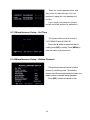
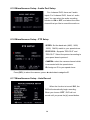
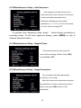
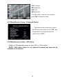
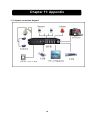
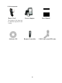
DVR4/9-SecuraNet™
USER MANUAL
SW242-4SN / SW242-9SN / SW243-4MB / SW243-9MB
Getting Started
FCC WARNING STATEMENT
This device complies with Part 15 of FCC Rules.
Operation is subject to the following two conditions:
(1) This device may not cause harmful interference, and
(2) This device must accept any interference received, including interference that may cause
undesired operation
Important Notice
All jurisdictions have specific laws and regulations regarding the use of cameras. Before using any
camera for any purpose, it is the buyer’s responsibility to be aware of all applicable laws and regulations
that prohibit or limit the use of cameras and to comply with the applicable laws and regulations. The
legality of watching people other than you changes from country to country and even state to state.
Contact your local government’s privacy information body or your local Police for more information on
what if any restrictions you may face.
WARNING: Important notice about correct usage of the power adapter
The correct orientation for the enclosed power adapter is in a vertical or floor mount position.
Precautions and Safety Instructions
Read this manual carefully before using the DVR. Follow the instructions for proper and safe use of
this product. Keep the instructions in a safe place for future reference.
- Use only the power adapter that is designed and supplied with this product
- Do not use this device near water or other liquids
- Do not use solvents or alcohols to clean the DVR – use a soft cloth only
- Ensure the vents on the sides and back of the DVR are not covered
- Do not use the DVR near heat sources such as heaters, stoves, fireplaces
- If the DVR has been damaged do not attempt to repair it yourself - contact Swann Technical Support for
assistance
Maintenance
For safety reasons, disconnect the power adapter before cleaning the DVR. Solvents and alcohols
may damage the casing. Use only a soft cloth to clean the unit. If necessary, lightly dampen cloth with
water only, for excess dirt and debris.
Contents
Chapter 1: DVR Features ........................................................................................................................ 1
Chapter 2: DVR Layout ........................................................................................................................... 2
2.1 Front Panel ........................................................................................................................................ 2
2.2 Rear Panel......................................................................................................................................... 3
2.3 Remote Control ................................................................................................................................. 4
Chapter 3: Hard Drive Installation............................................................................................................ 5
3.1 Installing a Fixed SATA Hard Disk ..................................................................................................... 5
Chapter 4: DVR Connections .................................................................................................................. 6
Chapter 5: Starting the DVR .................................................................................................................... 7
5.1 Firmware Version............................................................................................................................... 7
5.2 Detecting Installed Hard Drive ........................................................................................................... 7
5.3 Format Hard Drive ............................................................................................................................. 7
Chapter 6: DVR Menu System ................................................................................................................ 7
6.1 Navigating the Menus ........................................................................................................................ 8
6.2 Menu Overview.................................................................................................................................. 8
6.3 Camera Setup ................................................................................................................................... 9
6.4 Record Setup..................................................................................................................................... 9
6.5 Record Frame Rate ........................................................................................................................... 9
6.6 Video Quality ....................................................................................................................................11
6.7 Record Schedule ............................................................................................................................. 12
6.8 Sensor Setup................................................................................................................................... 12
6.9 H/W Sensor Setup........................................................................................................................... 12
6.10 Motion Detector Setup ................................................................................................................... 12
6.11 Hard Drive Setup ........................................................................................................................... 12
Miscellaneous Setup ............................................................................................................................. 12
6.12 Password Change ......................................................................................................................... 12
6.13 SET TIME ...................................................................................................................................... 13
6.14 HIDDEN CHANNEL....................................................................................................................... 13
6.15 AUDIO PORT SETUP.................................................................................................................... 14
6.16 PTZ SETUP................................................................................................................................... 14
6.17 Auto Record................................................................................................................................... 14
6.18 Auto Sequence ............................................................................................................................ 165
6.19 Keypad Tones .............................................................................................................................. 165
6.20 Image Parameters ....................................................................................................................... 165
6.21 Password Enable........................................................................................................................... 16
6.22 VGA Setup..................................................................................................................................... 16
6.23 Network Setup ............................................................................................................................. 127
6.24 Video Back Up ............................................................................................................................... 20
6.25 Reset Menu ................................................................................................................................... 22
Chapter 7: Record ................................................................................................................................. 22
7.1 Start Recording ................................................................................................................................ 22
7.2 Audio Recording .............................................................................................................................. 23
7.3 Stop Recording ................................................................................................................................ 23
7.4: Estimated Recording Lenth ............................................................................................................ 23
Chapter 8: Playback .............................................................................................................................. 24
8.1 Playback Control ............................................................................................................................. 24
Chapter 9: USB Programming(optional)............................................................................................ 25
9.1 Client Program Installation............................................................................................................... 25
9.2 Program Interface............................................................................................................................ 25
9.3 Program Running ............................................................................................................................ 26
Chapter 10: Specifications.................................................................................................................. 29
Chapter 11: Appendix ........................................................................................................................ 30
11.1 System connection diagram........................................................................................................... 30
11.2 Accessories.................................................................................................................................... 31
1. DVR Features
z
4-Channel: 4 BNC Camera Inputs - 2 BNC Video Outputs
9-Channel: 9 BNC Camera Inputs - 1 BNC Video Output
z
4-Channel: 2 Audio Inputs - 2 Audio Outputs
9-Channel: 1 Audio input - 1 Audio Output
z
View and Operate over Network (Broadband Connection Required)
z
NTSC or PAL System
z
Motion Detection with Sensitivity and Area Settings
z
Timed Schedule, Alarm and Motion Triggered Recording Modes
z
Hard Disk Support up to 500GB
z
Built-in USB 2.0 Port for Backup to Computer (4CH Model Only) or
USB Memory Stick Backup (9CH Model Only)
z
Supports PTZ Control via RS485 Port
z
Remote Control & Removable Hard Drive Tray Included
z
VGA Output (Optional)
1
2. DVR Layout
2.1 Front Panel (All Models)
1. Power switch
10. Record
23. IR Receiver
2. Removable HDD Tray
11. CH1
24. Up Arrow
3. HDD Lock
12. CH2
25. Select
4. USB 2.0 Interface
13. CH3
26. Left Arrow
5. Rewind
14. CH4
27. Down Arrow
6. Pause
15-19. CH5-9 (9CH DVR Only)
28. Right Arrow
7. Play
20. Mute Audio
8. Fast Forward
21. Display All Cameras
29. Power Indicator
30. HDD Indicator
9. Stop
22. Menu / Exit Menu
2
2.2 Rear Panel
1. Audio Input(s)
7. VGA Output (Optional)
13. CH6
2. Video Output(s)
8. LAN
14. CH5
3. CH4
9. Audio output
15. RS485 / Sensor Input /
4. CH3
10. CH9
Alarm Output
5. CH2
11. CH8
16. DC Power Input Jack
6. CH1
12. CH7
17. Grounding Terminal
3
2.3 Remote Control
1-9
0
ALL
Menu
Channel Select 1-9
Number
Display All Channels
Enter or Exit Menu
▲
Move Up / Left
▼
Move Down / Right
SEL
Select / Modify Item
Rewind
Play Recording
Fast Forward
●/
■
Record / Pause
Audio
Audio Input / Output
Stop Recording / Playback
4
3. Hard Drive Installation
WARNING:
Do not remove Hard Drive while DVR is running
Ensure HDD jumpers are set to MASTER prior to inserting drive
SW243-4MB / SW243-9MB has a hard drive pre-installed, please skip this step.
3.1 Installing a Fixed SATA Hard Disk
1 - Unlock and remove hard drive drawer from left side of the DVR
2 - Remove hard drive from drawer (if applicable)
3 - Align and connect power and SATA connectors to hard drive drawer
4 - Push the hard drive drawer back into the DVR and lock the drawer
5
4. DVR Connections
6
5. Starting the DVR
5.1 Firmware Version
After connecting the power adapter
and turn on the power button, the system
will boot-up and display the version and
released date of the DVR’s current
firmware.
5.2 Detecting Installed Hard Drive
DVR will detect the installed hard
drive and display the hard drive
information.
5.3 Format Hard Drive
When the DVR detects a new hard
drive you will be prompted to format the
hard drive before using the DVR
Press [SEL] to format or press
[MENU] to cancel.
7
6. DVR Menu System
6.1 Navigating the Menus
[MENU]: enters Main Menu
[▲, ▼, ◄ and ►]: move the cursor
[SEL]: select/modify settings
[MENU]: press again to exit or
return to previous menu.
6.2 Menu Overview
Camera Setup
Record Setup
Record Frame rate
Video Quality
Record Schedule
Main Menu
Sensor Setup
Hard Drive Setup
Miscellaneous Setup
Network Setup
Video Backup
Reset Menu
8
Change Password
Set Time
Hidden Channel
Audio Port Setup
PTZ Setup
Auto Record
Auto Sequence
Keypad Tones
Image Parameters
Password Control
VGA Setup
6.3 Camera Setup
Camera Setup allows you to turn
cameras on or off.
Press ▲, ▼, ◄ or ► button to select a
channel and then press [SEL] to modify the
setting ON or OFF.
Note: If a camera channel is set to off it will not record (Refer to 6.4 Record Setup)
6.4 Record Setup
Record Setup allows you to set up
recording channels.
Press ▲, ▼, ◄ or ► button to select a
channel, and then press [SEL] to modify the
setting to ON or OFF.
If a channel is disabled in Camera
Setup, it will not record and the DVR will
display “NOCAM” on screen.
6.5 Record Frame rate
The total frame rate is 50fps (PAL) or
60fps (NTSC). If the sum of the frame rate
you select for all cameras is greater than
50fps (PAL) / 60fps (NTSC), the DVR will
automatically adjust the largest frame rate
value to a smaller value.
Press ▲, ▼, ◄ or ► button to select a channel, and then press [SEL] to increase the
value or press [■STOP] to reduce the value.
Note: Higher frame rate shows smooth images but requires more hard drive space.
9
6.6 Video Quality
Video Quality has 4 different settings:
Highest, High, Normal and Low.
The higher the video setting the better
quality images, however higher quality
images require more hard drive space.
Press [SEL] to change the quality
setting.
6.7 Record Schedule
Setting the Record Schedule allows you to customize the type of recording depending
on the time of day.
The time line indicates 24 hours of a day
based on AM/PM (0 = 12).
Press ▲, ▼, ◄ or ► button to select a
time point, press [SEL] to modify the
recording mode.
NO-RECORD [
white]: DVR will not record during this time.
NORMAL-RECORD [
red]: DVR will record continuously.
SENSOR-RECORD [S]: DVR will record when sensor or motion is triggered.
NOTE: In order to activate the record schedule press the [ ] record button when viewing
the cameras. After pressing the [ ] record button if schedule is set to “NORMAL-RECORD”
the DVR will start to record immediately; if the schedule is set to be “SENSOR-RECORD”
the DVR will not start recording until a motion is detected by the DVR or an installed sensor
is triggered.
10
6.8 Sensor Setup
Sensor Record Time indicates how long
the recording time is when the motion or
sensor is triggered.
Alarm On Time indicates whether the
buzzer will sound when motion is detected.
CONT: Continuous alarm until any key is pressed.
OFF: No alarm
6.9 H/W Sensor Setup
Note: Sensors and extension alarms are not included with the DVR system and
may be purchased separately.
HARDWARE SENSOR SETUP:
There are 3 different modes for sensor
setting: NOT INSTALLED, NORMAL
-CLOSE and NORMAL-OPEN. Consult the
alarm purchased for more details on which
setting is required.
6.10 Motion Detector Setup
This section allows you to set up motion detection options for each camera.
MOTION DETECTOR SETUP:
ON/OFF: Enable or disable motion detection
recording
LEVEL: Sensitivity of motion detection. There
are 3 levels of sensitivity: Level 1-low, 3- highest.
AREA: Select detectable area on the screen.
11
Area Selection:
Press ▲, ▼, ◄ or ► button to select a
block, and press [SEL] button to set the block to
detect motion, The area is detectable when it is
clear, the area is not detectable when it is covert
by shadow.
6.11 Hard Drive Setup
This section will display the current hard drive status and usage options
OVERWRITE ENABLED:
ON: overwrite oldest video when hard drive is
full.
OFF: stop recording when hard drive is full.
HDD SIZE: indicates the total capacity of the hard drive installed in the DVR
HDD USED: indicates the space used in the hard disk drive for recording and
the percentage used
HDD FORMAT: will erase all video and data on the installed hard drive and
make it readable by the DVR
Note: You will be prompted for the password when formatting a hard drive.
The default password is “111111”
6.12 Miscellaneous Setup - Change Password
This option allows you to change the
system password. The password must be
composed with six characters.
All keys can be used as password key
except the [MENU] key, which is used to
exit.
12
Enter the current password first, and
then enter six characters as your new
password, repeat the new password to
confirm.
If you forget your password, please
contact technical support for assistance.
6.13 Miscellaneous Setup - Set Time
The system date and time format is
YYYY/MM/DD and HH:MM: SS.
Press ◄ or ► button to select the data to
modify, press [SEL] to modify. Press [MENU] to
save and return to previous menu.
6.14 Miscellaneous Setup - Hidden Channel
S
The system provides a function to hide a
channel in monitoring mode. The selected
channel can still be recorded while it’s hidden; the
hidden picture is viewable during playback.
Press [SEL] to select a channel to hide.
13
6.15 Miscellaneous Setup - Audio Port Setup
For 4-channel DVR, there are 2 audio
inputs. For 9-channel DVR, there is 1 audio
input. You can select the audio recording
function to ON or OFF, and select the video
channel that you like to record the audio on.
6.16 Miscellaneous Setup - PTZ Setup
SPEED: Set the baud rate (4800,9600,
19200,38400) match to your speed dome.
PROTOCOL: Supports “PELCO-D” and
“PELCO-P”. Select the protocol according to
your speed dome’s protocol.
CAMERA: select the camera channel which
is connected with the speed dome.
ID: Assign an ID to your speed dome.
Press [SEL] to select the camera, press ◄ or ► button to assign the ID.
6.17 Miscellaneous Setup - Auto Record
When the function is turned “ON”, the
DVR will automatically begin recording.
When you choose “OFF”, DVR will not
record until you press the [●] record button.
14
6.18 Miscellaneous Setup - Auto Sequence
Auto sequence function allows you to
view each active video channel in full screen
mode and display alternately. Auto
Sequence dwelling time can be also
adjusted to 1, 2, 5, 10, 15, 30 or 60 seconds,
or turn it off by choosing OFF.
To activate Auto Sequence mode, press [ ] button during monitoring or
recording mode. To exit auto sequence display, press [MENU] or any of
channel selection buttons.
6.19 Miscellaneous Setup - Keypad Tones
This function allows you the mute the
buzzer when pressing a button. Press [SEL]
to select ON or OFF.
'
6.20 Miscellaneous Setup - Image Parameters
You can adjust the image parameters
according to your needs.
Move the cursor to this selection and press
◄ or ► button to select a channel you want to
adjust, then press [SEL] button to edit
parameters.
15
CON: Contrast
BRI: Brightness
HUE: Hue
SAT: Saturation
Press ▲ or ▼ to select the item, and then
press [SEL] to adjust the value.
6.21 Miscellaneous Setup - Password Enable
The password will be required to control
the DVR when this option is set to “ON”, and
the password is not required when this
option is set to “OFF”.
6.22 Miscellaneous Setup - VGA Setup
Select a VGA resolution match to your CRT or LCD monitor.
NOTE: VGA video output is an optional function and may not be
available on all models
16
6.23 Network Setup
Network Setup allows you to prepare the DVR for viewing over the internet or local
network.
MAC ADDRESS: In a local area network(LAN),
the MAC (Media Access Control) address is
your computer’s unique hardware identity
code.(On an Ethernet LAN,it is the same as
your Ethernet address.) When you are
connected to the Internet from your computer
(or host as the Internet protocol thinks of it ),a
corresponding table relates your IP address to
your computer’s physical (MAC) address on the
LAN.
[Important]: This setting should only be changed if multiple DVRs are being setup on the same
network.
IP ALLOCATION: DVR supports DHCP and
Static IP modes. If your modem/router
supports DHCP mode use DHCP. When using
STATIC mode, you will be required to setup
your internet settings manually.
Note: After setting the DVR to DHCP mode
restart the unit.
IP Address: In a local network, the IP
address is a unique designated address for
your DVR recognized by your router.
Ensure this number is within the range
usable by your modem/router. Use the UP
“▲”and DOWN “▼” buttons to move the
cursor and use the “SELECT” button to
change the numbers. Once you have
finished the changes restart your DVR.
17
SUBNET MASK: Subnet Mask is used
to determine what subnet an IP address
belongs to. A number that is used to identify
a sub network so that IP addresses can be
recognized on a local area network.
Consult your modem/router for your LAN’s
subnet mask.
GATEWAY: Set this number to the gateway
set by your modem/router.
[NOTE] To adjustment the IP ADDRESS,SUBNET MASK and GATEWAY value, only when the
[STATIC] mode is being selected.
DNS ADDRESS: This code should be
provided by your local ISP.
18
HTTP PORT: This port number is used to
communicate with PC Client. The default
value is 80.
.
USER SETUP: When accessing the
DVR from a remote location you will be
prompted for a login and password. The
default is “admin” for full administrator
rights. Set “User ID” and password to setup
a user with limited rights to prevent
tampering.
DDNS SETUP:If you require an external
service to maintain a dynamic IP address
enter the user information here.
19
LAN-DVR Connection
See the diagram below for steps to connect your DVR to a local area network or the
internet. For remote monitoring from your computer,you must have a LAN connection
available or broadband Internet access.
You need to register a www.dyndns.org to get a free account .After registration,you will have a
username and password. You can also register your domain name on the website. Please refer to
Chapter 5,P. Network Setup for more details. There you will learn how to input the Dyndns username,
password,and domain name. You can log in from anywhere by using Internet Explorer and entering your
DVR’s domain name.
6.24 VIDEO BACK UP (For Optional USB Memory Stick Backup)
This function is only available for the model SW243-9MB / SW242-9SN
20
which supports USB Memory Stick device. If your DVR is with PC-link USB
interface, please refer to this section.
Move the cursor to “VIEW EVENTS”,
press [SEL] to enter event list. Press ▲ or
▼ button to move the cursor, and then
press [SEL] to select the event you like to
backup and return to previous menu.
The DVR system already indicated the
starting & ending time of the recording
event, move the cursor to “SIZE”, DVR
will automatically indicate the size of the
video you like to backup to USB momory
stick.
You can directly select the starting &
ending time of a recording video to
backup. Move the cursor to “START”
or “END”; press [SEL] to enter the
interface. Press ◄ or ► button to move
the cursor, and then press [SEL] to modify
the value.
Press [MENU] back to previous menu.
You can rename the backup file. Press
◄ or ► button to select the character you
want to modify, press ▲ or ▼ button to
select a character from the given
character list, and then press [SEL] to
enter.
Please note that the name must be ended
with “.MCG”.
21
Insert your USB memory stick into
DVR’s USB port.
Move the cursor to “BACKUP TO
USB DEVICE”, press [SEL] button.
DVR will check your USB device and
then start to copy the backup file.
Please read Chapter 8 about how to play back your recorded video.
6.25 Reset Menu
If you select this item, the system will restore all your settings to factory
default values. You need to enter your password to reset the menu.
Chapter 7: Record
7.1 Start Recording
Press [●] record button to start recording according to the record
schedule you have set. System will display some information on screen.
22
[●]: the red dot next to the channel name indicates that the channel is being
recorded.
[A-REC]: indicates the current record schedule is set to be
NORMAL-RECORD mode.
[S-REC]: indicates the current record schedule is set to be
SENSOR-RECORD mode.
[N-REC]: indicates the current record schedule is set to be NO-RECORD
mode.
[39%]: indicates the percentage of hard disk space used.
7.2 Audio Recording
[ ]: indicates this video channel is bundled with an audio port, and the
audio output is on.
[ ]: indicates the audio output is off.
[ ]: indicates the audio is being recorded and the audio output is on.
You could press [0] button on front panel to be mute mode for audio output.
The audio input can be still recorded while the output is mute.
7.3 Stop Recording
Press [■] stop button will stop recording. If password protection function is
enabled, system will prompt you to input password. Only correct password can
stop recording process.
7.4 Estimated Recording Length
Estimated record time based on 160Giga Byte HDD
Standard
NTSC
Standard
PAL
Quality
Highest
High
Normal
Lower
60fps
62
88
107
120
48fps
78
110
134
150
32fps
116
165
201
225
16fps
232
330
401
450
1fps
3720
5280
6420
7200
Quality
Highest
50fps
64
36fps
89
24fps
133
23
12fps
267
1fps
3200
High
Normal
Lower
90
110
123
125
153
171
188
229
256
375
458
513
4500
5500
6150
Unit: Hour
User also can calculate and estimate record time by below formula
160G Byte @16 frames per second @Normal quality
160(Gbyte) × 1024 (Mbyte) × 1024 (Kbyte)
7 (Kbyte/frame) × 16 (frame/sec) × 60(sec) ×60 (min)
Estimate hours is 401 Hours
Chapter 8: Playback
8.1 Playback Control
Press the [►] PLAY button goes into PLAYBACK mode. The newest record event will be played.
Press the [MENU] button during PLAYBACK
mode , then the system will list all the
recorded events. The latest record will be on
top of the list. Press the [ ▲UP ] or
[▼DOWN]buttons to select the start time to
l
h
Another way to search video is directly input
time period. Press the [MENU] button than
use [◄] or [►] button to select the TIME
search mode. Use [SEL] button to edit time
value, press “PLAY” to play the video.
24
Chapter 9: USB Programming (optional)
9.1 Driver Installation:
1.
2.
3.
4.
5.
Insert driver CD into your CD-ROM Drive.
Open CD directory.
Double click on the install applications.
Run “Install” program.
Follow the setup wizard to finish the
installation.
9.2 Program Interface
Button functions:
6
1
2
3
4
5
6
7
8
9
25
10
11
12 13 14 16 15 17 18
1.PTZ Control
11.Convert
AVI file
2.Zoom in,Zoom Out
Streams
12.Back one frame
3.HDD Play Mode
13. Record
4.File Play Mode
14.stop
5.Net Play Mode
15.Play
6.Event List
16.pause
7.Control Panel
17.fast forward
8.
Remote
DVR
to
18.forward one frame
Control
9.Change
Device
Storage
10.Capture Image
19.Playback Slider
20.Audio Slider
9.3 program running
HDD play mode:
System will detect the HDD automatically when you connect the USB cable to your PC
(4 Channel Model Only). A USB icon” ” will appear in the system tray (right bottom
” icon on your
corner of the screen). After you’ve seen the USB icon, double click “
desktop to run the program.
Note: if you do not follow above steps, the program will fail to detect HDD
Press
to open the video event lists.
26
Press
Press
to configure the program local settings
to play video.
FILE play mode: only when you plug a USB Memory stick into your PC (9 Channel)
27
Press “
” to open a folder and select the file you want play.
Double click the file.
NET play mode:
This mode allows you remote control you DVR via Internet.
Press “
” to popup the login window.
Fill in Host Name, Host Port, User Name and Password.
Press Login.
28
Chapter 10: Specifications
4 / 9-Channel DVR
Items
Descriptions
Video Standard
NTSC,PAL
Video Input/Output
4 Channels/2 Channels,9 Channels/1 Channel
Audio Input/Output
2 Channels/2 Channels,1 Channel/1 Channel
Resolution
NTSC:720X480@30fps(Each Ch)
PAL:720X576@25fps(Each Ch)
Features
Full-D1,1-CH/4-CH/9-CH Display
Resolution
NTSC:720X240@60fps(4/9Ch.Total)
PAL:720X288@50fps(4/9Ch.Total)
Features
Variable Frame Rate/Variable QL per
Channel
Quality
4-Level(Highest High Normal low)
Monitoring
Recording
Audio
ADPCM2 CODEC
Video
MPEG4
Motion Detection
Settable Window/Level
Microprocessor
32-bit RISC Processor
Network Interface
TCP/IP(RJ45)
Network Monitor
IE(Internet Explorer)
PTZ Interface
RS485
USB Interface
USB2.0
VGA Output
Optional
Remote control
IR remote control
Power supply
DC 12V/3A
29
Chapter 11: Appendix
11.1 System connection diagram
30
11.2 Accessories
Power Cord
Power Adaptor
User Manual
The design of the plug may
be different depends on the
country.
Software CD
Remote Controller
31
USB Cable (4ch DVR only)
Swann Technical Support
Swann Technical Support is available for any inquiries you may have.
Website: www.swannsecurity.com
USA/Canada: 1-800-627-2799, 1-877-274-3695
Australia: 1300 13 8324
Email: [email protected]
32