1
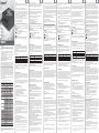
ENGLISH
DEUTSCH
Merci d’avoir choisi l’alimentation ENERMAX LIBERTY ECO! Veuillez lire avec
La ringraziamo per aver acquistato l’unità di alimentazione (PSU) ENERMAX
Muchas gracias por comprar nuestra fuente ENERMAX LIBERTY ECO. Le
Благодарим вас за выбор данного блока питания ENERMAX LIBERTY
Vielen Dank, daß Sie sich für dieses ENERMAX LIBERTY ECO-Netzteil (PSU)
attention ce manuel avant de procéder à l’installation de l’alimentation.
LIBERTY ECO . Prima di installare la PSU legga con attenzione questo manuale e
recomendamos que se familiarice bien con este manual de usuario.
ECO(БП)!
(PSU)! Please read this manual carefully and follow its instructions, before installing
entschieden haben! Bitte lesen Sie sich dieses Handbuch sorgfältig durch und
the PSU.
folgen Sie bitte seinen Anweisungen bevor Sie das Netzteil installieren!
ENERMAX est reconnu pour la haute qualité de nos produits et nos innovations
Queremos recordarle que los ordenadores actuales son muy vulnerables y
Компания ENERMAX является признанным во всем мире производителем
dans le domaine des produits pour PC. Cette alimentation LIBERTY ECO est
ENERMAX è conosciuta in tutto il mondo come il principale produttore di prodotti
necesitan condiciones especiales para funcionar sin problemas. Para evitar dichos
новаторской компьютерной продукции высочайшего качества, такой как
compatible avec les plus récents standards dans le domaine des alimentations pour
innovativi per PC di qualità elevata; ad esempio LIBERTY ECO è conforme con gli
fallos y maximizar la duración del sistema, le recomendamos asegurar que:
данный БП LIBERTY ECO, соответствующий новейшим стандартам блоков
qui demande de respecter certaines conditions pour fonctionner de façon optimale.
attenzione al fatto che il PC è un sistema delicato e che richiede condizioni
Su ordenador no esté al lado de una calefacción ni otro objeto irradiando calor
представляют собой точные системы, для бесперебойной работы которых
to draw your attention to the fact that PC is a delicate systems, which require very
können. Um solche Ausfälle zu vermeiden und um die Lebensdauer Ihres PC’s zu
Pour éviter tous problèmes et augmenter la durée de vie de votre PC, nous vous
specifiche per poter lavorare in modo ottimale senza problemi. Per prolungare la
Su ordenador no esté al lado de un objeto magnético
требуются совершенно определенные условия. Для предотвращения сбоев и
specific conditions to work best for you without failing. To avoid failures and to
verlängern, empfehlen wir Ihnen sicherzustellen, daß:
suggérons de :
durata del PC le suggeriamo di prestare attenzione a quanto segue:
Su ordenador no esté en un entorno húmedo sin polvo ni vibraciones
продления срока службы всего ПК рекомендуется выполнить приведенные
Su ordenador no reciba radiaciones solares directas
ниже условия.
Ne pas placer votre PC près d’un radiateur ou de toutes autres sources de chaleur
ПК НЕ ДОЛЖЕН располагаться с устройствами, генерирующими магнитное поле.
Your PC is NOT located in a moist and/or dusty and/or vibrating environment
Ihr PC nicht in einer feuchten und/oder staubigen und/oder
environnement soumis à des vibrations
Il PC NON deve essere posizionato nelle vicinanze di dispositivi magnetici.
ПК НЕ ДОЛЖЕН располагаться в местах с повышенной влажностью,пыльных
Your PC is NOT exposed to direct sunshine
vibrierenden Umgebung steht
Ne pas exposer votre PC à la lumière directe du soleil
Il PC NON deve essere posizionato in ambienti polverosi e/o umidi e/o soggetti
Le disuadimos de usar sistemas sin ventiladores, porque un nivel de
местах и в местах, подверженных вибрации.
Your PC is sufficiently cooled by additional fans
Ihr PC nicht dem direkten Sonnenlicht ausgesetzt ist
Suffisamment refroidir votre PC par l’ajout de ventilateurs supplémentaires si
a vibrazioni.
temperatura demasiado alta en el sistema disminuye la duración de vida de
ПК НЕ ДОЛЖЕН подвергаться воздействию прямого солнечного света.
Ihr PC ausreichend durch Lüfter gekühlt wird
nécessaire
Il PC NON deve essere esposto alla luce diretta del sole.
todos los componentes internos.
ПК должен достаточно охлаждаться дополнительными вентиляторами.
We do not recommend using PC systems with fanless cooling, because a
Wir raten vom Gebrauch von lüfterlosen PC-Systemen ab, da eine erhöhte
potentially high inner temperature decreases stability and lifetime of all
Gehäusetemperatur die Stabilität und Lebensdauer aller PC-Komponenten
beinträchtigt!
Nous ne recommandons pas d’utiliser un PC avec un système totalement
Не рекомендуется использовать ПК с пассивным охлаждением,так как
Si sconsiglia l’uso del raffreddamento senza ventole, poiché una temperatura
COMPATIBILIDAD
потенциальное повышение внутренней температуры может привести к
diminuera la durée de vie du PC et de tous ses composants.
interna potenzialmente elevata potrebbe diminuire la stabilità e la durata di
La serie ENERMAX LIBERTY ECO fuente es compatible con:
снижению стабильности и срока службы всех компонентов внутри ПК.
KOMPATIBILITÄT
ENERMAX LIBERTY ECO PSU Serie ist kompatibel mit:
Intel ATX12V Power Supply Design Guide v2.3 Spezifikation und
La série ENERMAX LIBERTY ECO est compatible avec:
Dieses Netzteil unterstützt keine MB`s mit ISA Erweiterungsslots, welche -5V
benötigen könnten. -5V wurde ab Intel ATX12V v1.3 Spezifikation abgeschafft.
s versiones v2.2, v2.01 e v2.2
СОВМЕСТИМОСТЬ
COMPATIBILITÀ
ATX System Design Guide v2.2, v2.1
БП серии ENERMAX LIBERTY ECO соответствует следующим стандартам:
La serie ENERMAX LIBERTY ECO è conforme con:
BTX / EEB / CEB / EPS12V
спецификация «Рекомендации по проектированию блоков питания Intel
Specifiche della Guida alla progettazione di alimentatori Intel ATX12V v2.3 e con
antérieures v2.0, v2.01 et v2.2
BTX / EEB / CEB / EPS12V
Intel ATX12V Power Supply Design Guide especificación v2.3 y también con la
COMPATIBILITE
Les spécifications Intel ATX12V Power Supply Design Guide v2.3 et les versions
ATX System Design Guide v2.2, v2.1
le precedenti.versioni v2.0, v2.01 e v2.2
compatible, porque no tiene una transmisión de -5V, requerida por algunos
BTX/ EEB/ CEB/EPS12V
Guida alla progettazione del sistema ATX v2.2, v2.1
equipos de ISA. La transmisión de -5V fue descontinuado por Intel ATX12V v1.3!
BTX/ EEB/ CEB/EPS12V.
Cette alimentation ne supporte pas les cartes mères avec un slot ISA, qui pourrait
BTX/ EEB/ CEB/EPS12V
Данный БП не поддерживает материнские платы с гнездом расширения ISA,
demander une source d’alimentation -5V. Cette dernière a été retirée des
Questo alimentatore non supporta schede madri con slot di espansione ISA, le
для которых может потребоваться напряжение -5 В. Напряжение –5 В не
spécifications Intel ATX12V v1.3.
quali potrebbero richiedere un’alimentazione da –5V, parametro che è stato
применяется, начиная со спецификации Intel ATX12V, версии 1.3.
INDICACIÓNES ADICIONALES
INFORMATIONS SUPPLEMENTAIRES
Si utiliza un cordón prolongador no lo puede utilizar con otros equipos de alto
consumo de corriente como impresas LASER para asegurar de no sobrepasar la
INFORMAZIONI AGGIUNTIVE
corriente máxima del cordón.
If you use multi outlets AC extension cables to provide the system power, do
Falls Sie Verlängerungskabel zur Systemversorgung nutzen, benutzen Sie diese
Si vous utilisez une multiprise comme source d’alimentation, veuillez ne pas
Se viene utilizzata una presa multipla per alimentare il sistema ed altre
bitte nicht gleichfalls für andere, viel Strom verbrauchende Ausrüstung wie
utiliser d’équipements à forte consommation électrique comme des imprimantes
apparecchiature, accertarsi che il cavo di alimentazione possa supportare il carico
radiators, on the same extension cable to avoid exceeding cable’s safety
Laserdrucker, etc., um die maximale sichere Durchleitungsfähigkeit des Kabels
laser, des radiateurs, pour éviter tous risques de surtension.
totale .
loading capacity.
nicht zu überschreiten.
Si vous souhaitez installer un onduleur pour votre PC, veuillez choisir un modèle
Se si decide di aggiungere l’UPS (Uninterruptible Power Supply) al sistema,
If you plan to add the UPS (Uninterruptible Power Supply) for your system,
Falls Sie USV (Unterbrechungsfreie Stromversorgung) für Ihr System verwenden
adéquate aux voltages nécessaires à son bon fonctionnement. Par exemple :
scegliere la capacità in watts/VA adeguata dell’UPS secondo la necessità dei
please choose adequate watts/VA capacity UPS for possible supplied
wollen, wählen Sie bitte ein USV mit adäquater Watt-VA Leistung für die zu
devices need. Ex.
versorgenden Geräte:
ELT400AWT-ECO
ELT500AWT-ECO
ELT620AWT-ECO
500W / 800VA
600W / 1000VA
800W / 1200VA
Please do not mistake VA capacity as Watts, or use insufficient power UPS.
This would result less UPS battery runtime or the inability to power the system
+3.3V
0.1-20A
+5V
+12V1
0.1-20A
+12V2
-12V
0.5-22A
+5Vsb
Total Power
Peak Power
0-3A
120W
0.1-22A
384W
(32A)
0-0.6A
7.2W
15W
Rated
0.1-24A
0.1-24A
0.5-24A
400W
440W
Rated
Combined
0.1-24A
130W
0.1-24A
0.1-30A
456W
(38A)
7.2W
0-0.6A
0-3A
15W
140W
0.5-30A
576W
(48A)
0-0.6A
0-3A
7.2W
15W
500W
550W
620W
680W
Min. load can reach to 0.1A for both +5V and +12V, and 0A for 3.3V / -12V +5Vsb
to support next generation PC power saving mode.
Over Voltage Protection
DC Rails
Trigger Range
+3.3V
28-40A
+5V
28-40A
+12V1/2
30-35A(400W / 500W) / 35-40A(620W)
DC Rails
Trigger Range
+3.3V
3.7-4.1V
+5V
5.7-6.5V
+12V1/2
13.1-14.5V
DC Rails
Trigger Range
Short Circuit Protection
Activated when any DC rails short circuited
MTBF
Dimension
Safety
EMC
Questa PSU è compatibile con UPS con onda sinusoidale simulate o alterata.
Dieses Netzteil ist kompatibel mit simulierten und reinen Sinuswellen-USV.
CABLES & CONNECTEURS
All connectors are designed to prevent insertion in wrong orientation. If you cannot
leichtes Einstecken möglich. Wenn Sie also einen original ENERMAX Anschluss
endommager votre système ou l’alimentation. La garantie sera annulée.
del PC, controllare se l’orientamento del connettore è corretto. Non forzare
easily insert a connector to the power supply or PC devices, please check if you are
nicht leicht mit einer Komponente verbinden können, überprüfen Sie bitte, ob Sie
Utiliser uniquement les câbles modulaires certifiés par ENERMAX et fournis avec
l’inserimento o modificare i connettori; in questo modo si potrebbe danneggiare
inserting the connector in the right orientation. Do not try by force to insert it nor
dies in der richtigen Ausrichtung versuchen. Versuchen Sie es keinesfalls mit
l’alimentation. Les autres câbles pourraient ne pas être compatibles et pourraient
l’alimentatore ed i componenti del PC, ed invalidare la garanzia.
modify the connectors. This might damage power supply and PC components, and
Gewalt oder verändern Sie auch nicht die Anschlüsse! Dies könnte das Netzteil
endommager votre alimentation, votre système, et annuler la garantie.
Utilizzare SOLO cavi modulari ENERMAX originali forniti con la PSU ENERMAX. I
warranty shall be void.
beschädigen und Sie verlören die Garantie!
cavi di terze parti potrebbero non essere compatibili e potrebbero danneggiare la
Use ONLY genuine ENERMAX modular cables coming with ENERMAX PSU. Third
Benutzen Sie nur original ENERMAX modulare Kabel für dieses PSU. Andere
PSU e/o il sistema PC, e potrebbero invalidare la garanzia della PSU.
party cables might not be compatible and might cause damage to your PSU and/or
Kabel könnten das PSU und Ihr System beschädigen und Sie verlören die Garantie.
EINSCHALTEN IHRES SYSTEMS
1. Le connecteur d’alimentation principale est correctement branché (24-pins).
Prima di avviare il sistema, controllare che:
BOOTING YOUR SYSTEM
Bevor Sie dieses tun, stellen Sie bitte sicher, daß:
2. Le connecteur CPU +12V (4 ou 8-pins), et/ou le connecteur 4P Molex
1. Il connettore di alimentazione (configurazione a 24-pin) sia collegato.
Before booting your system, please check that:
1. Mainboard-Stromanschluss(24-Pin Konfiguration) korrekt angeschlossen ist.
connector (if required by MB) is properly connected.
3. All other needed connectors are properly connected.
4. AC cord is properly connected to wall plug and PSU AC inlet.
5. Close your PC chassis.
ist,oder ein 4-Pin Molex-Stromanschluss (falls für MB erforderlich) korrekt
angeschlossen ist.
(si nécessaire) sont correctement branchés.
situations, the power supply will automatically turn off to avoid potential danger to
itself and other PC components. It is usually a malfunction of components or user’s
Activated when PSU heat sink >90~110 ƨ /194~230Ʃ
Environment
Operation ambient: 0~40ƨ / 32~104Ʃ (for full rated output)
Storage ambient: -40~70ƨ / -40~158Ʃ
Operation: to 85% relative humidity, non-condensing @ 25ƨ / 77Ʃ
Storage: to 95% relative humidity, non-condensing @ 50 ƨ /122Ʃ
Others
>0.97 (Active PFC)
Min. 80% @115VAC in 20%, 50% and 100% loading
One 12025 axian fan. 450-2000RPM(±10%) @ 40 ƨ
speed auto controlled.
> 100,000 hours @ 70% of full rated load, 230VAC /50Hz,25ƨ
(MIL-HDBK-217F standard)
150(w) x 86(h) x 140(d) mm
1. Turn I/O switch of power supply into “O” position, or disconnect AC cord from
wall plug and power supply AC inlet.
2. Check PSU for temperature by simply touching it. If it is very hot, this can be
caused by malfunction of case fans or the PSU fan itself and/or wrong positioning
of your PC.
3. Wait some minutes until PSU cools off.
4. Reconnect AC cord to wall plug and power supply AC inlet.
5. Turn I/O switch of power supply into “I” position, and reboot your system.
6. Check, if all fans are working.
7. Contact technical support of the respective manufacturer of the component which
you think might be the cause to the problem (e.g. MB, GPU or PSU).
UL/cUL, TUV, BSMI, CCC, GOST, CB
If you have any question or need support, please contact your reseller or nearest
CE(EN61204-3 standard), FCC, MIC
ENERMAX subsidiary/agent or ENERMAX headquarter service center.
© 2008, ENERMAX Technology Corporation, 15F-2, No. 888, Jing-Guo Road, Taoyuan City
(330), Taiwan (R.O.C.), Tel. +886-3-316-1675, Fax. +886-3-346-6640
All rights reserved. Actual product and accessories may differ from Illustrations. Information in
this manual is subject to change without prior notice. Printing errors and omissions excepted. All
trademarks, registered trademarks and/or product names mentioned are the property of their
respective owners.
CABLES Y ENCHUFES
3. Tous autres connecteurs nécessaires sont correctement branchés.
4. Le cordon d’alimentation doit être connecté à la prise électrique murale et à
l’alimentation.
por favor, revise si está insertado en la dirección correcta. Nunca lo intentezando
fuerzni cambie los pines del voltaje. Eso puede dañar la fuente e invalidar la
garantía.
Por favor utilice solamente cableados modulares originales de ENERMAX. Otros
o un enchufe 4-Pin Molex (si necesario) esté conectado correctamente.
4. El cable de la corriente (AC) está conectado correctamente con la fuente y el
enchufe!
5. Chiudere il telaio del PC.
6. Placer le bouton I/O de l’alimentation sur la position ‘I’ et votre PC est prêt à
6. Accendere l’alimentatore portando l’interruttore I/O su “I”; il sistema è pronto.
6. Coloque el interruptor de la fuente en la posición “I”.
démarrer.
FUNCIÓNES DE PROTECCIÓN Y SEGURIDAD
PROTEZIONE E SICUREZZA
La fuente ENERMAX LIBERTY ECO tiene varias funciones de protección y
SICHERHEITSFUNKTIONEN
PROTECTION, PRECAUTION ET SECURITE
La PSU ENERMAX è dotata di molte protezioni. In caso di situazioni anomale,
seguridad. En caso de mal funcionamiento se detendra para proteger todo el
Dieses ENERMAX LIBERTY ECO Netzteil verfügt über zahlreiche Sicherheitsfunktionen.
Im Falle der meisten abnormen Situationen wird sich das Netzteil zum Schutz Ihres
gesamten PC-Systems automatisch abschalten, um Schäden zu vermeiden. In den
meisten Situationen, in denen dies geschieht, ist eine Komponenten-Fehlfunktion oder
Fehlverhalten die Ursache. In solch einer Situation prüfen Sie bitte zuerst ihre
PC-Komponenten and die Umgebung auf Fehlfunktion(en), indem Sie folgendes
ausschalten und/oder abtrennen:
1. I/O Schalter des Netzteils auf “O“ & Kaltgerätekabel (Stromkabel) von Steckdose
und Netzteil.
2. Prüfen Sie das Netzteil durch einfaches Anfassen, ob dieses stark erhitzt ist.
Sollte dies der Fall sein, kann dies durch Fehlfunktion der Gehäuse-oder
Netzteillüfter verursacht sein oder durch ungenügende Anzahl von Gehäuselüftern
oder eine falsche PC-Positionierung.
3. Warten Sie einige Minuten, bis sich das Netzteil abgekühlt hat.
4. Schliessen Sie wieder das Kaltgerätekabel (Stromkabel) an Steckdose und Netzteil an.
5. Schalten Sie den I/O-Schalter am Netzteil auf “I”.
6. Prüfen Sie nun, ob alle Lüfter Ihres Systems arbeiten.
7. Kontaktieren Sie bitte den technischen Support des Herstellers der Komponente,
von der Sie glauben, dass Sie die Fehlfunktion verursacht (z.B. MB, Grafikkarte
oder ENERMAX).
Falls Sie Fragen haben oder Support benötigen, wenden Sie sich bitte an ihren
Händler, oder an ihre nächste ENERMAX-Niederlassung oder deren Agenten
oder an das ENERMAX Headquarter Service Center!
Cette alimentation intègre plusieurs protections. Dans des situations anormales,
l’alimentatore viene spento automaticamente per evitare pericoli verso le persone o
sistema de daños. En la mayoría de casos eso sera causado por un mal
celle-ci s’arrêtera automatiquement pour éviter tout danger pour vous votre PC. Ces
componenti
funcionamiento de componentes o mala utilización. En cualquier situación siempre
situations sont la plupart du temps liées à un disfonctionnement d’un composant ou
malfunzionamento di un componente o dalla negligenza dell’utente. In questo caso
sigua las instrucciones y desconéctela o apáguela:
à une mauvaise manipulation. Dans ces circonstances, merci de suivre les points
verificare il PC e l’ambiente di lavoro:
1. El interruptor de la fuente por “O“ y el cable corriente (AC) del enchufe y de la
suivants :
1. Portare l’interruttore I/O dell’alimentatore nella posizione “O”, o scollegare il cavo
1. Placer le bouton I/O de l’alimentation sur la position ‘O’, puis déconnecter le câble
d’alimentation de la prise murale.
viene
generalmente
attivata
dal
CA dalla presa a muro e l’alimentatore dall’ingresso CA.
fuente.
2. Todos los componentes, que no son absolutamente necesarios, como ODD.
Examine su temperatura por medio del tacto. Si esta caliente, puede ser, que
2. Controllare la temperatura della PSU toccandola. Se risulta molto calda potrebbe
2. Vérifier la température de l’alimentation en la touchant. Si elle est vraiment
chaude, cela peut être du à un mauvais fonctionnement du ventilateur ou à la
mauvaise position de votre PC.
esserci un malfunzionamento delle ventole o della ventola della PSU e/o la
los ventiladores del sistema o de la fuente estén dañados o su caja no tenga
posizione errata del PC.
ventiladores suficientes o es en una mala posición. (Lea nuestras recomendaciones
en el comienzo del manual)
3. Attendere alcuni minuti fino al raffreddamento della PSU.
3. Attendre quelques minutes que l’alimentation refroidisse.
4. Ricollegare il cavo CA alla presa a muro e l’alimentatore all’ingresso CA.
3. Espere. por unos minutos hasta que la fuente se haya enfriado.
4. Reconnecter le cordon d’alimentation au mur et à l’alimentation elle-même.
5. Portare l’interruttore I/O dell’alimentatore nella posizione “I” e riavviare il sistema.
4. Conecte de nuevo el cable corriente (AC) con enchufe y fuente.
5. Placer le boutons I/O de l’alimentation sur la position ‘I’ et relancer votre système.
6. Controllare se tutte le ventole funzionano.
5. Ponga el interruptor de la fuente en “I”.
6. Vérifier si tous les ventilateurs fonctionnent.
7. Contattare il supporto tecnico del costruttore del componente che si ritiene sia la
6. Examine Si todo los ventiladores están trabajando.
7. Contacter le service technique de chaque composant qui vous semble être la
causa del problema (p.e. MB, GPU o PSU).
7. Contacte. el fabricante del componente que piensa que esta causando el problema
cause de ce problème.
(como tarjetas o ENERMAX).
Si vous avez des questions, merci de contacter Enermax ou l’un de ses agents à
Nel caso di domande o necessità di supporto, contattare il rivenditore ENERMAX
travers le monde.
più vicino oppure il servizio di assistenza tecnica ENERMAX.
Si. tiene preguntas o si necesita ayuda, por favor contacte su vendedor o una
sucursal de ENERMAX o el centro mundial de soporte de ENERMAX
.
Web Site: http://www.enermax.com
E-mail: [email protected]
Web Site: http://www.enermax.com
E-mail: [email protected]
Используйте ТОЛЬКО фирменные модульные кабели ENERMAX, входящие в
комплект БП ENERMAX. Кабели других производителей могут быть не
совместимы и могут вызвать повреждение БП и (или) компьютерной системы.
Кроме того, использование кабелей других производителей приведет к
аннулированию гарантии на БП.
Перед загрузкой системы поверьте выполнение приведенных ниже условий.
1. Правильно подключен главный разъем питания (24-контактная
конфигурация).
2. Правильно подключены разъем питания ЦП +12 В (4- или 8-контактная
конфигурация) и (или) 4-контактный Molex-разъем (если требуется для
материнской платы).
3. Правильно подключены все остальные необходимые разъемы.
4. Кабель питания переменного тока надлежащим образом подключен к
электрической розетке и входному гнезду переменного тока БП.
5. Корпус ПК закрыт.
6. Питание системы включено переводом выключателя в положение
«I».После этого система готова к работе.
4. Kaltgerätekabel (Stromkabel) korrekt an Steckdose und Netzteil angeschlossen ist.
protezione
Не путайте мощность в ВА и Вт и не используйте ИБП недостаточной
мощности. Это приведет к сокращению времени работы ИБП от батареи или
невозможности питания системы от батареи.
Данный БП совместим с ИБП с аппроксимированной и чистой синусоидальной
формой выходного напряжения.
ЗАГРУЗКА СИСТЕМЫ
5. Cierre la caja del PC!
La
Web Site: http://www.enermax.com
ЗАЩИТА, МЕРЫ ПРЕДОСТОРОЖНОСТИ
ТЕХНИКИ БЕЗОПАСНОСТИ
И
ПРАВИЛА
БП ENERMAX оснащен несколькими средствами защиты. В большинстве
аномальных ситуаций блок питания автоматически выключается для
предотвращения повреждения БП и других компонентов ПК. Защита обычно
срабатывает вследствие неисправности компонентов ПК или небрежности
пользователей. В такой ситуации проверьте исправность устройств ПК и
условия эксплуатации.
1. Отключите питание БП, переведя выключатель в положение «O», или
отсоединив кабель переменного тока от электрической розетки и входного
гнезда переменного тока БП.
2. Проверьте температуру БП, прикоснувшись к нему. Перегрев БП может
быть вызван неисправностью вентиляторов корпуса ПК или вентилятора
БП, либо неправильным размещением ПК.
3. Подождите несколько минут, пока БП не остынет.
4. Подсоедините кабель переменного тока к электрической розетке и к
входному гнезду переменного тока БП.
5. Переведите выключатель БП в положение «I» и выполните перезагрузку
системы..
6. Проверьте работоспособность системы.
7. Обратитесь в службу технической поддержки производителя компонента,
который, возможно, вызывает проблему, например материнской платы,
графической платы или БП.
E-mail: [email protected]
Web Site: http://www.enermax.com
Web Site: http://www.enermax.com
500W / 800VA
600W / 1000VA
800W / 1200VA
1. El enchufe de la tarjeta madre (24-pin configuración) esté conectado
5. Fermer le boîtier de votre PC.
PC.
ELT400AWT-ECO
ELT500AWT-ECO
ELT620AWT-ECO
Antes de encenderlo por favor asegúrese de que:
4. Il cavo CA sia collegato alla presa a muro e all’ingresso CA della PSU.
del
Рекомендованная наименьшая выходная мощность UPS
(с учетом КПД и PFC при соответствующей нагрузке)
Все разъемы имеют конструкцию, предотвращающую установку в
неправильной ориентации. Если подсоединение разъема к блоку питания или
устройствам ПК затруднено, удостоверьтесь в том, что подсоединение разъема
выполняется в правильной ориентации. Не пытайтесь применять усилие при
установке разъемов или изменять их. Это может привести к повреждению
блока питания и компонентов ПК, и гарантия будет аннулирована.
3. Alle anderen erforderlichen Stromanschlüsse korrekt angeschlossen sind.
5. Dann schliesen Sie das PC-Gehäuse und verschrauben es!
Модель БП
КАБЕЛИ И РАЗЪЕМЫ
3. Todos los otros enchufes necesarios están conectado correctamente.
3. Tutti i connettori necessari siano collegati.
В случае применения для питания системы удлинительных кабелей
переменного тока с несколькими розетками не подключайте к тому же
удлинителю оборудование с высокой потребляемой мощностью, такое как
лазерные принтеры и радиаторы отопления, с целью предотвращения
превышения допустимой нагрузки удлинительного кабеля..
Если в систему планируется добавить источник бесперебойного питания
(ИБП), выбирайте ИБП с достаточной мощностью в ваттах (или ВА) для
питания подключаемых устройств. Пример.
dirección equivocada. Meter un enchufe en un zócalo tiene que ser fácil. Si no
2. El enchufe del CPU +12V AUX (si necesario) esté conectado correctamente,
il connettore Molex 4P (se necessario) sia collegato.
Дополнительное замечание
Todos los enchufes son diseñados para que sea imposible conectar cables en la
2. Il connettore di alimentazione a +12V della CPU (configurazione a 4 o 8-pin), e/o
6. Drücken Sie am Netzteil den I/O-Schalter auf “I”, das System ist jetzt bereit!
This ENERMAX PSU features multiple protections. In case of most abnormal
Esta fuente esta compatible con SAI tipos simulados y puros sinusoidales.
correctamente.
6. Turn on the power supply by switching the I/O switch to “I”, and your system
PROTECTION, SAFETY & SECURITY
sistema en modo de batería.
ENCENDIENDO EL SISTEMA
DEMARRER VOTRE SYSTEME
AVVIARE IL SISTEMA
2. CPU +12V power connector (4 or 8-pin configuration), and/or a 4P Molex
500W / 800VA
600W / 1000VA
800W / 1200VA
cables podrían dañar el sistema e invalidar la garantía.
Avant de démarrer votre système, veuillez vérifier les points suivants:
2. CPU +12V AUX Stromanschluss (falls für MB erforderlich) korrekt angeschlossen
ELT400AWT-ECO
ELT500AWT-ECO
ELT620AWT-ECO
puede meter fácilmente el cableado modular original de ENERMAX en un zócalo,
Se non si riesce ad inserire con facilità il connettore all’alimentatore o ai dispositivi
8.5-9.5V
Cooling
l’impossibilità ad alimentare il sistema in modalità batteria.
sens d’insertion. Ne pas forcer ou modifier les connecteurs. Cela pourrait
+12V1/2
Efficiency
prendre le relais d’alimentation en cas de coupure électrique.
nahezu unmöglich ist. Der Anschluss an kompatible Verbindungen ist daher durch
your PC devices and working environment for malfunction:
Power Factor
im Batteriemodus zu starten, resultieren.
CABLES & CONNECTORS
negligence to trigger off a protection event. In such circumstance, please check
Humidity
Il risultato potrebbe essere una perdita della capacità della batteria dell’UPS o
Tutti i connettori sono progettati per evitare l’inserimento con l’orientamento errato.
2.0-2.4V
Temperature
USV. Dies würde in reduzierter USV-Laufzeit oder im Unvermögen das System
parvenez pas à insérer facilement un câble dans un connecteur, veuillez vérifier son
3.3-3.7V
Over Temperature
Protection
Non confondere la capacità VA con Watts, o usare UPS con potenza inadeguata.
seraient insuffisantes. Cela réduira son autonomie ou pire cela l’empêcherait de
Alle Anschlüsse sind so entworfen, dass ein Anschluss in falscher Ausrichtung
1. Main power connector (24-pin configuration) is properly connected.
(se basa por eficiencia y PFC a carga respectiva)
que provocaría una disminución de la duración SAI o problemas el encender el
Veillez à ne pas utiliser un onduleur dont les capacités exprimées en VA ou Watts
PC system, and use of third party cable shall void PSU warranty.
Capacidad recomendada mínima del SAI
Modelo de la fuente
Por favor, no confunda capacidad de VA con vatios ni utilice un SAI insuficiente, ya
CAVI E CONNETTORI
+5V
Activated when AC input voltage < 80VAC
500W / 800VA
600W / 1000VA
800W / 1200VA
ELT400AWT-ECO
ELT500AWT-ECO
ELT620AWT-ECO
Tous les connecteurs sont étudiés pour éviter une mauvaise insertion. Si vous ne
+3.3V
Activated when output power >110~150% of rated max. load
(Basata sul efficienza e PFC con il rispettivo carico)
KABEL & ANSCHLÜSSE
(DC)
Over Power Protection
Capacità minima di corrente consigliata per gli UPS
Modello di PSU
Bitte verwechseln Sie nicht VA-Kapazität mit Watt, noch nutzen Sie ungenügende
This PSU is compatible with simulated and pure sine wave UPS.
Under Voltage Protection
Under Voltage Protection
(AC)
500W / 800VA
600W / 1000VA
800W / 1200VA
500W / 800VA
600W / 1000VA
800W / 1200VA
ELT400AWT-ECO
ELT500AWT-ECO
ELT620AWT-ECO
is ready.
Protection Circuits
Over Current Protection
ELT400AWT-ECO
ELT500AWT-ECO
ELT620AWT-ECO
ELT620AWT-ECO
Combined
0.1-24A
(gemäß Effizienz & PFC bei entsprechender Last)
se debe emplear uno con capacidad de vatios-VA suficiente como:
in battery mode.
AC Input
Combined
Empfohlene kleinste USV-Kapazität
PSU Modell
Si utiliza un SAI(Sistemas de Alimentación Ininterrumpida) para su sistema,
dispositivi. Esempio.
Modèle d’alimentation Capacité minimale suggérée pour votre onduleur
Suggested min. UPS output power capacity
(Based on efficiency & PFC at respective load)
ATX12V, версия 2.3» с обратной совместимостью с версиями 2.0, 2.01 и 2.2;
ATX System Design Guide v2.2, v2.1
not use other high power consumption equipment, such as laser printers or
PSU Model
Si su Placa Madre (MB) utiliza un bus “ISA“, es posible que esta fuente no sea
Рекомендации по проектированию систем ATX, версия 2.2, версия 2.1;
cancellato dalle specifiche Intel ATX12V v1.3 e versioni successive.
ZUSÄTZLICHE HINWEISE
ПК НЕ ДОЛЖЕН располагаться рядом с радиатором и иными источниками тепла.
fanless, car cela peut provoquer une hausse importante de température qui
tutti i componenti all’interno del PC.
abwärtskompatibel mit v2.0, v2.01, v2.2
–5V power. –5V has been cancelled from Intel ATX12V v1.3 specification
Su ordenador sea refrigerado lo suficiente por parte de los ventiladores
IlPC DEVE essee raffreddato a sufficienza.
Only a technician, authorized by ENERMAX, is allowed to perform maintenance
service! Warranty is subject to void under unauthorized attempt to open the power
case or modification of any kinds, even attempted only, of the power supply or its
components!
Rated
(ПК)
fonte di calore.
Precaution Notice
100-240VAC, 50-60Hz, automatic switching, Active PFC
Max. operation range: 90-265VAC
7.5A-3.5A
9.5A-4A
DC Output
компьютеры
Ne pas placer votre PC dans une pièce humide, et/ou salle, et/ou un
EXTRA NOTICE ABOUT UPS
6.7A-3A
что
Ihr PC nicht neben einer magnetischen Quelle steht
© 2008, ENERMAX Technology Corporation
Input Voltage
Помните,
Your PC is NOT located near a magnetic device
onwards.
Input Current
систем.
Il PC NON deve essere posizionato nelle vicinanze di radiatori o a qualsiasi altra
This PSU does not support MB with ISA expansion slot, which might require
Spec.
настольных
Ne pas placer votre PC près d’une source magnétique
BTX/ EEB/ CEB/EPS12V
ELT500AWT-ECO
для
Ihr PC nicht neben einer Heizung oder einer anderen Wärmequelle steht
ATX System Design Guide v2.2, v2.1
ELT400AWT-ECO
питания
Your PC is NOT located near a radiator or any other heat producing device
Manual Del Usuario
Model
настоящее
genau definierte Bedingungen benötigen, um optimal ohne Ausfälle arbeiten zu
compatible with v2.0, v2.01 and v2.2
ENERMAX LIBERTY ECO Series Power Supply Specification
прочтите
complies with the newest standard for desktop class power supplies. We would like
Manuale dell’Utente
Web Site: http://www.enermax.com E-mail: [email protected]
внимательно
standard più recenti in merito ad alimentatori per desktop. Le chiediamo di porre
Intel ATX12V Power Supply Design Guide v2.3 specification and downward
If you are uncertain whether or not your ENERMAX PSU is defective, please
contact your dealer/reseller for support!
БП
PC. Nous voudrions attirer votre attention sur le fait qu’un PC est un système fragile,
ENERMAX LIBERTY ECO series is compliant with:
This ENERMAX Technology Corporation product is warranted to be free from
defects in material and workmanship for a period of three (3) years from the date of
purchase. ENERMAX Technology Corporation agrees to repair or replace the
product, at its own option and at no charge, if, during the warranty period, it is
returned to nearest ENERMAX Technology Corporation subsidiary/agent with all
shipping charges prepaid and bearing a return merchandize authorization (RMA)
number, and if inspection reveals that the product is defective. Charges for
removing or installing the product are excluded under the terms of this warranty
agreement. This warranty shall not apply to any product, which has been subject to
connection to a faulty power source, alteration, negligence, or accident, or to any
product, which has been installed other than in accordance with these instructions.
In no event shall ENERMAX Technology Corporation, or its subsidiaries, or agents
be liable for damages for a breach of warranty in an amount exceeding the
purchase price of this product!
установкой
möchten Sie darauf hinweisen, daß moderne PC’s sehr empfindlich geworden sind
COMPATIBILITY
ENERMAX will not be responsible for damages caused by following situations:
Opening of the PSU case and/or modification of any component or cable without
ENERMAX’ written authorization.
Ignoring connector’s wrong insertion prevention design by attaching a connector
to a device in wrong orientation.
Connecting too many devices to one cable unit by using additional adaptor
(Y cables).
Usage of non-genuine ENERMAX modular cables.
Damage caused by natural phenomena or uncontrollable forces, such as
lightning, flooding, fire, earthquake, etc.
Перед
руководство и выполняйте все приведенные в нем инструкции.
segua le istruzioni.
innovative PC products of highest quality just like this LIBERTY ECO, which
User’s Manual
482010240510, Ver. 1.0, September 2008
РУССКИЙ
Sehr geehrte Kundin, sehr geehrter Kunde,
components inside your PC!
Pуководство для пользователя
ESPAÑOL
Thank you for choosing this ENERMAX LIBERTY ECO power supply unit
increase lifetime of your entire PC, we suggest you to make sure that:
Manuel d’utilisateur
ITALIANO
Dear customer,
We, ENERMAX, are globally renowned as the leading manufacturer of
Benutzerhandbuch
FRANCAIS
E-mail: [email protected]
E-mail: [email protected]
Web Site: http://www.enermax.com
Information in this document is subject to change without notice. ©2008 ENERMAX Technology Corporation. All
rights reserved. Reproduction in any manner without the written permission of ENERMAX is strictly forbidden.
E-mail: [email protected]
Die Information in diesem Dokument unterliegen unangekündigten Änderugen. ©2008 ENERMAX Technology
Corporation. Alle Rechte vorbehalten. Die Vervielfältigung dieses Dokuments in jeglicher Form ist ohne schriftliche
Genehmigung seitens ENERMAX streng untersagt.
Les information contenues dans ce document peuvent être soumises à des modifications sans préavis.
©2008 ENERMAX Technology Corporation. All rights reserved. Toute reproduction, par quelque manière que ce
soit, est strictement interdite sans l’autorisation écrite de ENERMAX.
Le informazioni contenute in questo documento sono soggette a variazioni senza preavviso. © 2008 ENERMAX
Technology Corporation. Tutti i diritti riservati. È severamente proibita la riproduzione di qualsiasi parte senza il
permesso scritto di ENERMAX.
La información contenida en este documento está sujeta a cambios sin previo aviso. © 2008 ENERMAX Technology
Corporation. Reservados todos los derechos. Se prohibe estrictamente la reproducción de este documento en
cualquier forma sin permiso por escrito de ENERMAX.
Информация в этом документе может изменяться без уведомления. ©2008 ENERMAX Technology
Corporation. Все права защищены. Воспроизводство в любом виде строго запрещается без письменного
разрешения ENERMAX .
ENGLISH
NAME OF PARTS
15
0.0
mm
mm
0.0
14
DEUTSCH
NAMEN DER TEILE
FRANCAIS
ELEMENTS PRATIQUES
ITALIANO
NOME DELLE PARTI
ESPAÑOL
NOMBRES DE PARTES
РУССКИЙ
НАИМЕНОВАНИЕ ДЕТАЛЕЙ
1
Output cable.
1
Ausgangskabel.
1
Câble de sortie.
1
Cavo di uscita.
1
Cable del corriente.
1
Выходной кабель.
2
12cm fan.
2
12cm Lüfter.
2
Ventilateur 12cm.
2
Ventola da 12cm.
2
Ventilador de 12 cm.
2
12-см вентилятор.
3
AC inlet.
3
Stromeingang.
3
Connecteur AC.
3
Ingresso CA.
3
Toma de corriente.
3
Гнездо входа переменного тока.
4
I/O switch: individual PSU on/off switch (I=ON, O=OFF).
4
I/O Schalter: separater Netzteil An/Aus-Schalter (I=AN, O=AUS).
4
Bouton I/O. ( I= ON, O=OFF)
4
Interruttore I/O: interruttore di accensione/spegnimento PSU (I=ON, O=OFF).
4
Interruptor I/O: separado interruptor de la fuente por En/Paro (I=En, O=Paro).
4
Выключатель: отдельный выключатель БП (I=Вкл., O=Выкл.).
1
86.0mm
When assemble or maintain the system, please remove AC cord from AC
Entfernen Sie immer das Stromkabel vom Netzteil und schalten Sie den
Lorsque vous assemblez ou réparez votre système, veuillez débrancher le câble
Quando si monta o viene eseguita la manutenzione del sistema, rimuovere il
Desconecte siempre el cable de la corriente de la fuente y apague el interruptor
При сборке и обслуживании системы отсоединяйте кабель переменного
inlet,or turn I/O switch into “O” position.
I/O-Schalter auf „O“ während Sie am System arbeiten.
d’alimentation ou bien mettre le bouton sur la position ‘O’.
cavo dall’ingresso CA, o portare l’interruttore I/O sulla posizione “O”.
I/O a “O“ para mantener el sistema.
тока от гнезда переменного тока или переводите выключатель в положение
«O».
4
2
3
MODULAR SOCKETS & CABLE
5
5
5P BLACK sockets
MODULARE SOCKEL & KABEL
5
The black sockets are for modular cable to power drives or other peripheral.
6
7
ATTACHING / DETACHING THE MODULAR CABLES
7
8
Attaching the modular cable to PSU
CABLES MODULAIRES ET SOCKETS
5
МОДУЛЬНЫЕ ГНЕЗДА И КАБЕЛЬ
5
5
5
Zócalos negros de 5 Pines
Los zócalos negros son para cables modulares en discos (HDD, ODD)
Peripherie.
périphériques.
periferiche.
o periféricos.
Sockets ROUGES 12P
6
Attacchi a 12P ROSSI
Rote 12P Sockel
Les sockets rouges sont réservés aux cartes graphiques, CPU et mémoire.
Gli attacchi rossi sono per i cavi modulari che alimentano la scheda grafica, la
Die roten Sockel sind für modulare Kabel für Grafikkarten oder CPUs oder RAM.
Die roten Sockel sind für modulare Kabel für Grafikkarten oder CPUs oder RAM.
CPU o la RAM.
Modulare Kabel an das Netzteil anschliessen
BRANCHER / DEBRANCHER UN CABLE MODULAIRE
7
Brancher un câble modulaire à l’alimentation
ATTACHING / DETACHING THE MODULAR CABLES
7
Collegamento del cavo modulare alla PSU
6
Zócalos rojos de 12 Pines
и других периферийных устройств.
6
CONECTAR Y EXTRAER CABLES MODULARES
7
CONECTAR CABLES MODULARES CON LA FUENTE
Le connecteur 5-pins / 12-pins des câbles modulaires porte une flèche blanche :
Il connettore a 5-pin / 12-pin sul cavo modulare e l’attacco modulare della PSU
5-Pin / 12-Pin enchufes de los cables modulares y los zócalos de la fuente tienen
arrow mark.
des Netzteils haben weisse Pfeilmarkierungen.
Procédez ainsi pour connecter un câble:
sono segnati con una freccia bianca.
marcas blancas de flecha.
The steps to make correct connection is easy:
Folgende Regeln machen die Anwendung einfach:
1. Connecteur noir sur socket noir, et rouge avec rouge.
Le procedure per il collegamento sono estremamente semplici:
1. Enchufes negros con zócalos negros y rojos con rojos.
1. Black connector to black socket, and red to red.
1. Schwarze Stecker zu schwarzen Sockeln und rote zu roten.
2. Les flèches blanches se rencontrent.
1. Connettore nero su attacco nero, e rosso su rosso.
2. Flecha con flecha.
2. Arrow mark to arrow mark.
2. Pfeilmarkierung zu Pfeilmarkierung.
3. Ainsi la connexion est possible.
2. Simbolo della freccia su simbolo della freccia.
Красные гнезда предназначены для модульного кабеля питания
ПОДСОЕДИНЕНИЕ И ОТСОЕДИНЕНИЕ МОДУЛЬНЫХ КАБЕЛЕЙ
7
3. Quindi è possibile collegare il connettore.
Modulare Kabel vom Netzteil entfernen
8
Débrancher un câble modulaire de l’alimentation
8
Todos 5-Pin / 12-Pin enchufes de los cables modulares tienen ganchos para
sûreté qui s’accrochent au socket de l’alimentation. Pour retirer le câble,appuyez
Il connettore a 5-pin / 12-pin sul cavo modulare è dotato di due ganci per bloccarlo
guardar con los zócalos de la fuente. Para removar un cable modular pulsa hacia
sur les deux crochets et tirer doucement.
con l’attacco modulare della PSU. Quando viene scollegato il cavo modulare
las flechas y desenchufa el enchufe cuidadoso.
Alle 5-Pin / 12-Pin Stecker auf den modularen Kabeln haben zwei Haken zum
Les connecteurs 5-pins / 12-pins des câbles modulaires ont deux crochets de
5-pin / 12-pin connector on modular cable has two hooks to lock with the PSU’s
Einrasten mit den Sockeln des Netzteils. Um ein modulares Kabel zu entfernen,
modular sockets. When unplug the modular cable from PSU, please press two
pressen Sie bitten gegen die zwei Haken und ziehen Sie den Stecker dann sanft
hooks together and gently pull out the cable.
heraus.
8
8
CONNECTOR ON NATIVE CABLE
9
24P Mainboard
ANSCHLÜSSE AUF NATIVEN KABELN
9
24-pin configuration supports latest ATX/BTX PC & dual CPU EEB/CEB
server/workstation boards.
10
11
10
11
12
13
4+4P CPU +12V, in combined mode
10
24P Mainboard
dalla PSU, premere i due ganci contemporaneamente e tirare delicatamente il
9
24P tarjeta madre
La configurazione a 24-pin supporta schede madri per workstation/server ATX/BTX
PC e CPU EEB/CEB duali più recenti.
EEB/CEB Server/Workstation.
4+4P CPU +12V, in “Kombiniertem Modus”
4+4P CPU +12V, in “Getrenntem Modus”
4-pin configuration supports most ATX/BTX systems. Please use the connector
4-Pin Konfiguration unterstützt die meisten ATX-/BTX-Systeme. Bitte verwenden
with “12V” marking.
Sie das Modul mit der „+12V” Markierung.
ANSCHLÜSSE AUF MODULAREN KABELN
12
12
6+2P (8P) PCI Express, in “kombiniertem Modus”
8-pin configuration supports latest extreme graphic cards, which require 8pin
8-pin Konfiguration unterstützt die neuesten Grafikkarten, welche diesen 8-Pin
PCI-E connector.
PCI-E Stecker benötigen.
13
Scheda madre a 24P
serveur/station de travail Bi-CPU.
einige Ein-Socket PC-Systeme.
6+2P (8P) PCI Express, in split mode / 6P PCI Express
9
ENCHUFES POR CABLES MODULARES
Zwei-Socket EEB/CEB Server/Workstation Boards.
CONNECTORS ON MODULAR CABLE
13
CONNETTORE SU CAVO NATIVO
La configuración 24-Pin soporta generaciones nuevas de ATX/BTX & dual-socket
single CPU PC systems.
6+2P (8P) PCI Express, in combined mode
Carte mère 24P
Cette configuration 24-pins supporte les dernières cartes ATX/BTX PC & EEB/CEB
8-Pin Konfiguration unterstützt Zwei-Socket Server/Workstation Systeme und
11
9
24-Pin Konfiguration unterstützt neueste ATX/BTX PC-Generationen &
8-pin configuration supports dual CPU server/workstation systems and some
4+4P CPU +12V, in split mode
CONNECTEURS NATIFS
6+2P (8P) PCI Express, in “getrenntem Modus” / 6P PCI Express
6-pin configuration supports most performance PCI-E graphic cards, which
6-Pin Konfiguration unterstützt die meisten Grafikkarten, welche diesen 6-Pin
require 6-pin PCI-E connector.
PCI-E connector Stecker benötigen.
10
4+4P CPU +12V, en mode combiné
10
La configuration 8-pin supporte les serveurs/stations de travail Bi-CPU.
11 4+4P
CPU +12V, en mode séparé
4+4P CPU +12V, en “modo combinado”
La configuración 8-Pin soporta dual-socket Server/Workstation & algunos
alcuni sistemi di PC con CPU singole.
sistemas single-socket ATX/BTX.
CPU a 4+4P +12V, in modalità split
11
4+4P CPU +12V, en “modo separado”
La configuration 4-pins supporte les systèmes ATX/BTX. Utiliser le connecteur
La configuración 4-Pin soporta la mayoría de los sistemas ATX-/ BTX. Use el
marqué « 12V ».
con indicazione “12V”.
enchufe parcial marcado con “+12V”.
6+2P (8P) PCI Express, en mode combiné
CONNETTORI SU CAVO MODULARE
ENCHUFES DE CABLES MODULARES
12
12
La configuration 8-pins supporte les dernières cartes graphiques PCI-E.
13
10
La configurazione a 8-pin supporta sistemi di server/workstation per CPU duali e
La configurazione a 4-pin supporta molti sistemi ATX/BTX. Utilizzare il connettore
LES CONNECTEURS DES CABLES MODULAIRES
12
11
CPU a 4+4P +12V, in modalità combinata
6+2P (8P) PCI Express, en mode séparé / 6P PCI Express
13
PCI Express a 6+2P (8P), in modalità combinata
РАЗЪЕМ НА ФИРМЕННОМ КАБЕЛЕ
9
Материнская плата с 24-контактным разъемом
24-контактная конфигурация совместима с новейшими материнскими
платами ATX, BTX и двухпроцессорными материнскими платами EEB, CEB
для рабочих станций и серверов.
10
Комбинированный разъем ЦП 4+4 контакта +12 В
8-контактная конфигурация совместима с двухпроцессорными серверами и
рабочими станциями, а также с некоторыми однопроцессорными системами.
11
Разделенный разъем ЦП 4+4 контакта +12 В
4-контактная конфигурация совместима с большинством систем ATX и BTX.
Используйте разъем с маркировкой «12V».
РАЗЪЕМЫ НА МОДУЛЬНОМ КАБЕЛЕ
12
Комбинированный разъем PCI Express с 6+2 контактами (8 контактами)
La configurazione a 8-pin supporta le schede grafiche più recenti, che richiedono
La configuración 8-pin configuración soporta las nuevas tarjetas gráficas, que
8-контактная конфигурация совместима с новейшими сверхпроизводительными
un connettore PCI-E a 8pin.
necesitan este enchufe de 8-Pin PCI-E.
графическими картами, для которых требуется 8-контактный разъем PCI-E.
PCI Express a 6+2P (8P), in modalità split / PCI Express a 6P
13
La configurazione a 6-pin supporta le prestazioni di molte schede grafiche
La configuration 6-pins supporte la plupart des cartes graphiques PCI-E.
6+2P (8P) PCI Express, en “modo combinado”
Отсоединение модульного кабеля от БП
5-контактный (12-контактный) разъем на модульном кабеле оснащен двумя
крючками, фиксирующимися на модульных разъемах БП. При отсоединении
модульного кабеля от БП сожмите два крючка по направлению друг к другу
и аккуратно вытяните разъем кабеля
cavo.
9
Подсоединение модульного кабеля к БП
5-контактный (12-контактный) разъем на модульном кабеле и модульное
гнездо на БП промаркированы белой стрелкой.
Ниже приведена процедура правильного соединения.
1. Черный разъем соединяется с черным гнездом, красный разъем – с
красным гнездом.
2. Стрелка совмещается со стрелкой.
3. Выполнение этих условий позволяет правильно подсоединить разъем...
REMOVAR CABLES MODULARES DE LA FUENTE
Scollegare il cavo modulare dalla PSU
Detaching the modular cable from PSU
12-контактные КРАСНЫЕ гнезда
графической карты, ЦП и ОЗУ.
5-Pin / 12-Pin Stecker auf den modularen Kabeln und den modularen Sockeln
8
5-контактные ЧЕРНЫЕ гнезда
Черные гнезда предназначены для модульных кабелей питания приводов
Los zócalos rojos son para cables modulares de tarjetas graficas o CPU o RAM.
5-pin / 12-pin connector on modular cable and PSU’s modular socket has a
Then you can easily plug in the connector.
8
Attacchi a 5P NERI
Gli attacchi neri sono per i cavi modulari che alimentano le unità e le altre
VERBINDEN & ENTFERNEN VON MODULAREN KABELN
7
CABLES Y ZÓCALOS MODULARES
Les sockets noirs sont réservés aux branchements des disques et autres
6
6
Sockets NOIRS 5P
ATTACCHI E CAVI MODULARI
Die schwarzen Sockel sind für modulare Kabel für Laufwerke (HDD, ODD) oder
12P RED sockets
The red sockets are for modular cable to power graphics card, CPU or RAM.
6
Schwarze 5P Sockel
PCI-E, che richiede un connettore PCI-E a 6-pin.
6+2P (8P) PCI Express, en “modo separado” / 6P PCI Express
13
Разделенный разъем PCI Express с 6+2 контактами (8 контактами) или
La configuración 6-pin configuración soporta la mayoría de las tarjetas
6-контактный разъем PCI Express
gráficas, que necesitan este enchufe de 6-Pin PCI-E.
6-контактная конфигурация совместима с большинством высокопроизводительных
графических карт для PCI-E, для которых требуется 6-контактный разъем PCI-E.
14 SATA
14
For SATA drives. *1
15 4P
14
15
Molex
SATA
14
15
4P Molex
For IDE/SCSI drives or some AGP graphic card with traditional 4P power in
Für IDE/SCSI Laufwerke oder einige AGP Grafikkarten mit traditionellem 4-Pin
socket. *2
Stecker. *2
SATA
14
15
4P Molex
SATA
14
Per unità SATA. *1
Pour les disques durs / lecteur SATA.*1
Für SATA-Laufwerke. *1
15
4P Molex
14
15
4P Molex
SATA
Для SATA-приводов. *1
Para ODD tipo SATA de nueva generación. *1
Per unità IDE/SCSI o alcune schede grafiche AGP con alimentazione 4P
Pour les disques durs IDE/SCSI ou quelques cartes graphiques AGP.*2
SATA
15
4-контактный Molex-разъем
Для IDE/SCSI-приводов и некоторых графических карт для AGP с
Para ODD tipo IDE/SCSI de ”vieja” generación con enchufe 4-P. *2
nell’attacco. *2
традиционным 4-контактным гнездом питания. *2
16
16 FDD
16
FDD
16
FDD
16
FDD
16
FDD
16
Разъем дисковода гибких дисков (FDD)
For floppy drive.
Für Floppy-Laufwerke.
Pour lecteur de disquette
Per unità floppy.
Para discos “Floppy”.
Для дисковода гибких дисков.
*1 Some SATA drives might accept SATA or 4P Molex power. Normally, use
*1 Einige SATA-Laufwerke unterstützen SATA & 4-Pin Molex Stecker. Schliessen
*1 Certains HDD SATA peuvent accepter une alimentation SATA ou 4P Molex.
*1 Alcune unità SATA potrebbero accettare l’alimentazione SATA o Molex 4P. In
*1 Unos discos duros de SATA soportan SATA e 4-Pin Molex enchufes.Conecta
*1. Некоторые SATA-приводы могут получать питание по разъему SATA или
either one of power connector to power the driver, BUT NOT BOTH! Please
Sie nur einen Stecker an! Lesen Sie sonst im Handbuch des Laufwerks nach!
Utiliser l’un des deux connecteurs, et JAMAIS les deux en même temps.
genere, utilizzare uno dei due connettori di alimentazione per alimentare l’unità, MA
vd. Solamente un enchufe! Examiná vd. su manual del disco duro por detalles!
4-контактному Molex-разъему. Обычно для питания привода используется
check the drive’s manual for details.
NON ENTRAMBI! Per i dettagli controllare il manuale dell’unità.
только один разъем питания, НО НЕ ОБА! Подробные сведения см. в
*2 Einige MB´s unterstützen diesen Stecker zur zusätzlichen Stromversorgung
*2 Certaines cartes mères nécessitent de partager le connecteur 12V. Si votre
*2 Some MB might require this connector to share the +12V current from 20-pin
des 20-Pin MB-Steckers. Falls Ihr MB einen 24-Pin MB-Sockel besitzt, sollten Sie
carte mère supporte déjà le connecteur 24 pins, il n’est pas nécessaire d’ajouter le
*2 Alcune schede madre richiedono questo connettore per condividere la corrente
addicional aparte del enchufe 20-Pin de la tarjeta madre. Si su tarjeta madre
mainboard connector to PCI-E slot. If your MB already supports 24-pin
den 4-Pin Molex Stecker nicht anschliessen. Lesen Sie dies bitte im Handbuch
4P Molex. Merci de vérifier dans le manuel de votre carte mère.
a +12V dal connettore a 20-pin della scheda madre allo slot della PCI-E. Se la
obtiene un zócalo de 24-Pin MB, vd. no debería conectar este enchufe de 4-Pin
*2. Для некоторых материнских плат этот разъем может потребоваться для
mainboard connector, you may not add the 4P Molex power on it.
des MB´s nach!
scheda madre supporta il connettore a 24-pin, potrebbe non essere necessario
Molex. Examiná vd. su manual de la tarjeta madre por detalles.
подачи напряжения +12 В с 20-контактного разъема материнской платы на
Please check the MB’s manual for details.
* 2 Unas tarjetas madres soportan este enchufe para suministrar corriente
aggiungere un’alimentazione Molex 4P. Per i dettagli controllare il manuale della
scheda madre.
руководстве по эксплуатации привода.
гнездо PCI-E. Если материнская плата поддерживает 24-контактный разъем,
на нее не удастся подавать питание с 4-контактного Molex-разъема.Подробные
сведения см. в руководстве по эксплуатации материнской платы.