Transcript
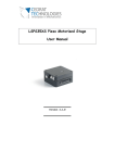
1
Minimum Hardware Requirements
Intel® Workstation Board S5520SC
Quick Start User's Guide
To avoid integration difficulties and possible board damage,
your system must meet the following minimum requirements:
• Processor: Minimum of one Intel® Xeon® Processor 5500 Series
or one Intel Xeon Processor 5600 Series.
• Supports maximum 95 watt processor in the Intel® Server
Chassis SC5600Base.
Chassis SC5650WS.
• Heat Sink(s): Minimum of one active heat sink for the Intel®
Server Chassis SC5600Base and SC5650WS.
• AC Power: SSI EPS 12V compliant power supply.
Recommended minimum of 670 Watts with 3 A of standby
current, or calculate your system power demand with the power
budget tool.
For details on these chassis or to select a third-party
chassis, please visit:
http://support.intel.com/support/motherboards/server.
For a complete list of compatible processors, heat sinks, and memory, see:
http://support.intel.com/support/motherboards/server/s5520SC/
CAUTION:
When installing the server board into a reference chassis,
refer to the reference chassis instructions.
Supported
Processor
Supported
Graphics Card
Service Guides are also available on the CDs that accompanied
your Intel® Workstation Board S5520SC.
In the Intel®
Server Chassis
SC5600Base
In the Intel®
Server Chassis
SC5650WS
Maximum 95
watt processor
One maximum
150 watt graphics
card in PCI
Express* Slot 6
Maximum 130 watt processor
Do not remove the three circular
knockouts that are at the edge next to
the openings for the NIC, USB, Serial A,
and 1394 ports. Use caution so you do
not deform the shield.
Attach the Labels to the I/O Shield
Place your
Intel® Server
Chassis on a flat anti-static
surface to perform the
following integration
procedures. Observe ESD
procedures before
reaching inside to make
server board connections
or install components.
• Memory Type: Minimum of one 1 GB, 240-pin,
RDIMM or UDIMM, DDR3-800, DDR3-1066, or DDR3-1333.
3
A
B
Shield installs from inside
of chassis. The labels
should be visible from the
outside of the chassis.
ONE maximum 300 watt graphics card in
PCI Express* Slot 6 or TWO maximum
150 watt graphics cards. Empty PCI
Express* Slot 3 when a graphics card is
installed in PCI Express* slot 4.
Install Workstation
Board Bumpers
B
Warning
Installation and service of
this product should only be
performed by qualified service
personnel to avoid risk of injury from
electrical shock or energy hazard.
Caution
Observe normal ESD
[Electrostatic Discharge]
procedures during system
integration to avoid possible
damage to server board and/or
other components.
Tools Required
#2 Phillips*
screwdriver
Install the Workstation Board
Intel ® Server Chassis
SC5600Base Shown
IMPORTANT NOTE: If you are using a
non-Intel server chassis, see your
chassis documentation for preparatory
steps prior to server board installation.
A. Insert Workstation Board
• When using the Intel® Server Chassis
SC5600Base, remove the rear chassis fan
and then insert the I/O connector
side (back) of the board first.
• When using the Intel®
Server Chassis SC5650WS,
remove the front drive bay
and rear chassis fan, and then
insert the front of the board first.
Slide the board back so the I/O
connectors fit through the I/O shield.
5b
Intel ® Server Chassis
SC5650WS Shown
Front
Edge of
Board
CAUTION: The underside
of the processor has
components that may damage
the socket wires if installed
improperly.
A
Orient the processor with the socket
so that the orientation notches on
the processor align with the two
orientation posts on the socket.
Install the processor as shown.
Components
E39546-009
Processor must align
correctly with the
socket opening
before installation.
®
A
Close the
load plate
all the
way as
shown.
A
Close the socket lever.
C
Remove the protective cover after it been
automatically disengaged from the load plate.
B
Orientation Posts
C
1. When opening a socket, DO NOT TOUCH
the gold socket wires.
Attach auxiliary power signal
connector to the workstation board.
Attach the CPU 2 power connector
to the workstation board.
D
Attach the main power connector to
the workstation board.
CAUTION:
Note the location of the latch on each
power cable connector and align it with the
matching tab on each workstation board socket.
IMPORTANT NOTE: If you are using a non-Intel
server chassis with an ATX power supply, see
the documentation that came with your chassis
for installation information.
DO NOT DROP processor
into the socket!
Cautions:
A
Push the lever handle down
and away from the socket to
release it.
B
Rotate the lever open all
the way.
A
Push the rear tab with your
finger tip to bring the front
end of the load plate
up slightly.
A
A
In
B
B
CPU Power
Connector Detail
Auxiliary Signal
Power Detail
Latch
D
Tab
CPU 2 Socket
C
A
A
Take the processor out
of the box and remove
the protective shipping
cover.
A
Main Power
Connector Detail
CPU 1 Socket
C. Remove the
Processor
Protective Cover
Open the load plate as shown.
Make Workstation Board Power Connections
C
A
B. Open the Load Plate
B
Attach the CPU 1 power connector
to the workstation board.
MIC
Chassis Back
Panel Opening
CPU 2 Socket
6
NIC
USB 2
USB 0
1
ID
Intel ® Server Chassis
SC5650WS shown
B
B
B
A. Open the Socket Lever
CPU 1 Socket
A
A
Install the Processor(s)
B
Intel® Server
Chassis
SC5650WS
E. Close Load Plate and Socket Lever
Push shield firmly into
chassis opening until
it clicks into place.
NIC
USB 1
USB 2
3
D
2. When unpacking a processor, hold by the
edges only to avoid touching the gold
contact wires.
• Intel® Server Chassis SC5650WS: Push down
firmly to engage the snap-top standoffs at the
location indicated by the solid red arrow [ ].
Use screws to attach the board to the chassis at
the nine locations indicated by the solid blue
arrows [ ].
Orientation Notches
Anti-static
wrist strap
Intel is a registered trademark of Intel Corporation or its
subsidiaries in the United States and other countries.
*Other names and brands may be claimed as the property
of others. Copyright © 2011, Intel Corporation. All rights
reserved.
The Intel Server Chassis SC5600Base and the Intel Server Chassis SC5650WS use different screws
to attach the workstation board to the chassis. Use the screws indicated for your chassis.
For a non-Intel server chassis, use the fasteners that came with your chassis.
®
Intel® Server
Chassis
SC5600Base
Install the Processor(s) ... continued
D. Install the Processor
B. Attach the Workstation Board
B
In
Locate the five circles as shown.
5a
• Intel® Server Chassis SC5600Base: Attach the
board to the chassis at the nine locations indicated
by the solid blue arrows in the figure [ ] and at
the one location indicated by the solid red arrow [ ].
Place the board into the chassis, making
sure that back panel I/O openings and
chassis standoffs align correctly.
I/O Openings
Read all caution and safety
statements in this document
before performing any of the
instructions. Also see the Intel ®
Server Board and Server Chassis
Safety Information document at:
http://support.intel.com/support/
motherboards/server/sb/cs-010770
.htm for complete safety information.
4
Insert one side edge of
shield as shown.
lA
1394
C
as shown.
CAUTION: To avoid damage to the board,
do not lay flat with the component side down.
Warning
A
Line
Seria
LSB
Attach the Bumpers
C Remove the backing from each bumper.
D Press a bumper onto each of the five circles.
Prepare Workstation Board
A Rotate board to show underside and hold upright
B
Diagn
ostic
LEDs
MSB
Remove the backing from the I/O
shield labels included with your
server board.
Press each label onto the I/O
shield as shown.
Install the I/O
shield
NOTE: If you are using an Intel® Server Chassis you must install the chassis
bumpers included with the chassis. Refer to your Intel® Workstation Board
and Intel® Server Chassis Quick-Start User’s Guide for proper bumper
installation guidelines. If you are using a non-Intel server chassis that
includes bumpers, refer to the non-Intel server chassis documentation for
the correct bumper installation procedure. If the non-Intel server chassis
does not include bumpers, then you should consult with the chassis vendor
to determine whether bumpers are required or not.
Labels on outside
face of I/O shield
Note: Make sure you install the labels
on the correct side of the I/O shield.
Note the orientation of the cutouts in
the drawing before attaching your labels.
NOTE: Graphics cards with power greater than 75 W must be self-cooled
with exhaust out the back of the chassis.
If you are not familiar with ESD (Electrostatic Discharge) procedures
used during system integration, please see the Intel® Workstation Board S5520SC
Service Guide, available on the Intel® Server Deployment Toolkit 3.0 CD or at
http://support.intel.com/support/motherboards/server/S5520SC/manual.htm
Installing the I/O Shield and Attach I/O Labels
Prepare the I/O shield
Observe normal ESD
(Electrostatic Discharge)
procedures.
• Supports maximum 130 watt processor in the Intel® Server
Thank you for buying the Intel® Workstation Board
S5520SC. The following information will help you
integrate your new server board into a server
chassis. The Intel® Workstation Board S5520SC
is designed for use with the Intel® Server
Chassis SC5600Base and the Intel® Server
Chassis SC5650WS.
2
Preparing
the Chassis
Go to Side 2