1
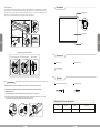
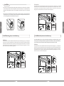
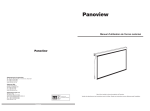
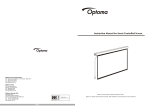
Installation Guide for
Panoview Motorized screen
Optoma Asia Corporation
5F., No 108, Minchiuan Rd., Xindian City, Taipei 231
Tel: 886-2-2218-2360
Fax: 886-2-2218-2313
www.optoma.com.tw
Easy to operate and reflects vivid and colourful images.
Optoma USA
Applicable for education venues, meeting rooms, control rooms,
boardrooms, training facilities and home theatres.
715 Sycamore Drive
Milpitas, CA 95035 USA
Tel: 408-383-3700
Fax: 408-383-3702
www.optomausa.com
Especially suited for specific use projectors.
Optoma Europe Ltd.
42 Caxton Way
The Watford Business Park
Watford Hertfordshire WD18 8QZ UK
Tel: +44 (0) 1923 691 800
Fax: +44 (0) 1923 691 888
www.optoma.co.uk
ISO9001:2000
International Certification
Product Safety
To ensure your safety, please read "Product Manual and Warnings"
b.Connect to a power source (Please make sure it is the right voltage)
c.Turn the switch to position 2 to lower the screen; it will come down slowly. When it is all the way down, it will stop automatically.
d.Turn the switch to position 1 to retract the screen; it will go up into the metal casing. When it is all the way up, it will stop automatically.
e.To stop any time while the screen is in motion, turn the switch to 0.
The ceiling or wall used for fixture installation must be secure to prevent the screens from falling.
While installing electrical motors, please hire professionals or your local dealer to ensure safety.A misconnection may lead
to fire or leaks.
Keep all infrared wireless products away from fluorescent lighting as it may cause malfunctions.
Please read the following as any damage to the screen surface will affect the quality of the picture:
1.Avoid contact or touching the screen surface as it may cause scratches or tears.
2.Do not write or draw on the surface
Picture 1
3.Clean the screen with a soft cloth and lukewarm water. Do not use any detergent or cleaning products.
Picture 3
Picture 2
Roll up the screen after every use. Ensure that the screen is level when installing; do not pull on the sides or fold the screen.
To prevent unnecessary damage, the operating and maintenance of the screen should be done by adults.
1
Product Features
3.12V burst controller. (Figure 4-6 )
a.One end of the signal cable insert into the 12V jack of the handle controller, the other end insert into the 12V output hold
of the projector.
b.Press the control switch of the handle controller to the location.
c.When running the projector, the screen will spread the fabric automatic by synchronous; when closing the projector, screen
will be back automatic by synchronous too.
d.If you don't need to use the12V burst controller, please draw off the burst line directly, then control it by your hand.
Trendy and Elegant
12V Plug
The metal casing is compact and elegant. The white cover is coated with PVC technology that enhances the
feel and esthetics.
Unique Rolling Rod
Special designs on the rod allow minimal contact with the screen's surface resulting in minimal damage to the screen.
Picture 4
Picture 5
Picture 6
Top-Quality Motor
Equipped with the world-renowned power motor. It is quiet, secure, and precise.
Resolution
The matte white material provide different brightness and viewing ranges, flexible to suit every setting. The matte white
allows a wider view range and soft colors.
3. Automatic remote control (Please see section on Remote Control)
To avoid overheating the motor , do not continually retract and lower the screen for over 4 minutes at a time . If the motor
overheats, it will need a cool down time of 2 minutes. The motor does not need any lubricants.The drop and retract limit of the
screen is factory preset to an optimal configuration. Please ask your local dealer or professional to adjust settings to avoid
damaging the motor.
Location
It is suited for various venues such as education facilities, home theatres , boardrooms , or othe entertainment
sites.
Motor adjusting slot
Warnings
Ignoring the safety warnings may lead to
injuries and /or damaging the product.
Fixtures should be installed in a secure place
to avoid accidents or the screen falling.
Do not connect any electrical attachments
or remote controls.
Roll up the screen after every use . Leaving
it hanging for a long period of time may cause
the fabric to loosen.
Please contact your local dealer for repairs or
maintenance. Please contact our company if y ou
have any further questions . Avoid taking
apart the fixtures yourself. Loose parts may
cause the screen to fall.
Refrain from hanging anything on th e screen a s
it may cause the screen to fall.
Do not take apart and replace with unknown parts. If there are any problems, please contact your local dealer. Product specifications
are subject to change.
6
Description
Ceiling Mount
U s i n g a t a p e m e a s u r e f in d o u t t h e d i s t a n c e b e t w e e n t h e t w o k e y h o l e s o n t h e c a s i n g ( f i g u r e 1 ) . A cc o r d in g t o
the measurement, use the drill to drill identical holes of the appropriate size on the ceiling and ensure that it is
l e v e l ( f i g u r e 2 & 3 ) . S c re w i n t h e ho o k s c r e w s ( n o t p r o v i d e d ) , a n d l i f t t h e s c r e e n i n t o t h e h o o k s c r e w s t o
hang (figure 4). To ensure that the screen is level, use a level to check (figure 5).
Metal Casing
A
End Cap
2
5
Screen Fabric
Hanger
2
Rod
3
Wall/Ceiling Mounting Installation
Accessories
Wood material installation Concrete material installation
Ceiling mount
Hidden installation
Ceiling mount
Ceiling mount
Installation Manual
5mm Allen Key (1 )
Wall mount
Wall mount
Wall mount
Optional
Instructions
5 x 60mm Anchor and bolts (6 )
5 x 60mm Screw ( 6 )
Panoview projection screens are controlled by a manual switch or an automatic remote control.
1. Tear off the glue cloth fixed on the bottom rod,ensure the bottom rod is not stuck by the casing.
2. Manual switch control
Connection between the manual control and screen (remark:for this kind of product only)
a. At the end of the controller wire, take the plug and insert it securely into the inlet located on the left side of the screen casing.
ensure the position of the plug is properly matched with the inlet and screw down the nut.
Motorized Screen Power Specifications
Socket
Slot
Slot
Screw
Plug
Voltage
Frequency
Watts
230V/120V/100V
50Hz/60Hz
36W/36W
Application
Applies up to 120" motorized screens
Ceiling Mount
Installation
1.This projection screen should be installed at the best possible viewing position for the audience. Take out all the parts
from the packaging and follow the accessories guideline to ensure you have all the parts . The parts needed will vary
depending on which installation you choose to use. For installation on a wood wall or ceiling , use 5 x 60 anchors and
screws.
U s i n g a t a p e m e a s u r e f in d o u t t h e d i s t a n c e b e t w e e n t h e t w o k e y h o l e s o n t h e c a s i n g ( f i g u r e 1 ) . A cc o r d in g t o
the measurement, use the drill to drill identical holes of the appropriate size on the ceiling and ensure that it is
l e v e l ( f i g u r e 2 & 3 ) . S c re w i n t h e ho o k s c r e w s ( n o t p r o v i d e d ) , a n d l i f t t h e s c r e e n i n t o t h e h o o k s c r e w s t o
hang (figure 4). To ensure that the screen is level, use a level to check (figure 5).
2. There are two way for wall brackets to fix on the housing. As you can see on the figure 1, which is our normal fixed
way(namely factory set ). While the other fixed way is to interchange the left and right wall brackets, and then fix
onto the housing(namely functional installation way, as figure 2).
A
2
3
Figure 1
Factory-set installation way
Installation one
4
Figure 2
3
Functional installation way
Factory-set installation way
Wall Mount
Using a tape measure, measure the distance between the two keyholes on the casing ( figure 1) . According to the
measurement, use the drill to drill identical holes of the appropriate size on the wall (use a smaller drill bit than the
actual screws) and ensure that it is level (figure 2 & 3) . Screw in the appropriate screws, either 5 x 60 by itself for
wood walls or with anchors for drywalls , leaving enough space at the end to hang the casing (figure 4) . To ensure
that the screen is level, use a level to check (figure 5).
Installation two
Functional installation way
For Functional installation way, we can not only use wall mounting, ceiling mounting to fix the housing, but also can just nail
the housing onto the wall and ceiling via wall brackets using spare screws. Please make sure that, using this installation way,
you have to take off the factory-set wall brackets and then interchange left & right brackets before mounting.
Wall Mount
Using a tape measure, measure the distance between the two keyholes on the casing ( figure 1) . According to the
measurement, use the drill to drill identical holes of the appropriate size on the wall (use a smaller drill bit than the
actual screws) and ensure that it is level (figure 2 & 3) . Screw in the appropriate screws, either 5 x 60 by itself for
wood walls or with anchors for drywalls , leaving enough space at the end to hang the casing (figure 4) . To ensure
that the screen is level, use a level to check (figure 5).