1
34008709cover_AA.fm Page 1 Mardi, 8. juillet 2008 9:33 09
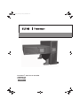
Powerware® 9135 Two-in-One UPS
5000/6000 VA
User’s guide
34008709cover_AA.fm Page 2 Mardi, 8. juillet 2008 9:33 09
34008709/AA
34008709safety_AA.fm Page 1 Mardi, 8. juillet 2008 9:34 09
ENGLISH
Safety guidelines
Read before installing product
Safety of persons
◗ The UPS has its own internal power source (the battery).
Consequently, the power outlets may be energised even if the UPS is disconnected from the AC-power source.
◗ Dangerous voltage levels are present within the UPS. It should be opened exclusively by qualified service personnel.
◗ The UPS must be properly earthed. Measurements are required to ensure that the total leakage current of the UPS and the protected
equipment does not exceed 3.5 mA by checking their characteristics.
◗ The UPS and their batteries must be kep in a ventilated room or compartment. This equipment should only be used in a supervised indoor environment.
◗ The battery supplied with the UPS contains small amounts of toxic materials. To avoid accidents, the directives listed below must be observed :
– Never burn the battery (risk of explosion).
– Do not attempt to open the battery (the electrolyte is dangerous for the eyes and skin).
– Comply with all applicable regulations for the disposal of the battery.
– Batteries constitute a danger (electrical shock, burns). The short-circuit current may be very high. Precautions must be taken for all handling :
remove watches, rings, bracelets and any other metal objects, use tools with insulated handles.
Product safety
◗ The UPS connection instructions and operation described in the manual must be followed in the indicated order.
◗ UPS must be connected to a nearby wall outlet that is easily accessible. The UPS can be disconnected from the AC-power source by removing the power cord.
◗ Check that the indications on the rating plate correspond to your AC-power system and to the actual electrical consumption of all the equipment
to be connected to the UPS.
◗ Never install the UPS near liquids or in an excessively damp environment.
◗ Never let a foreign body penetrate inside the UPS.
◗ Never block the ventilation grates of the UPS.
◗ Never expose the UPS to direct sunlight or source of heat.
◗ If the UPS must be stored prior to installation, storage must be in a dry place.
◗ The admissible storage temperature range is -25° C to +55° C.
Special precautions
◗ Once installed and connected to the AC power source for the first time, the battery will start to charge. Full charging to obtain the rated battery
backup time requires at least 8 hours.
◗ Before and after the installation, if the UPS remains deenergised for a long period, the UPS must be energised for a period of 24 hours, at least
once every 6 months (for a normal storage temperature less than 25° C). This charges the battery, thus avoiding possible irreversible damage.
◗ During the replacement of the battery module, it is imperative to use the same type and number of element previously mounted in the UPS,
in order to maintain an identical level of perforamance and safety. In case of doubt, don’t hesitate to contact our after sales department (for
more information, refere to the web site www.mgeops.com).
FRANÇAIS
Consignes de sécurité
A lire avant toute installation du produit
Sécurité des personnes.
◗ L’ASI possède sa propre source d’énergie interne (batterie).
Les prises de sorties peuvent donc être sous tension même si l’ASI est déconnectée du réseau électrique.
◗ Présence de tension dangereuse à l’intérieur de l’ASI. Son ouverture ne peut être effectuée que par un personnel qualifié.
◗ L’ASI doit être impérativement reliée à la terre. S’assurer lors de l’installation que la somme des courants de fuites de l’ASI et des équipements
qu’elle alimente ne dépasse pas 3.5 mA en vérifiant leurs caractéristiques.
◗ Les ASI et leurs batteries doivent être installées dans une pièce ou un compartiment ventilé. Ces appareils doivent être utilisés uniquement
dans un environnement intérieur contrôlé.
◗ La batterie fournie avec l’ASI contient une faible quantité de substances toxiques. Afin d‘éviter tout accident, les consignes suivantes doivent
être respectées :
– Ne pas jeter la batterie dans le feu (risque d’explosion).
– Ne pas tenter d’ouvrir la batterie (électrolyte dangereux pour les yeux et la peau).
– La mise au rebut doit être réalisée conformément à la législation en vigueur.
– La batterie présente des risques électriques (chocs électriques, brûlures). Le courant de court-circuit peut être très important. Des
précautions doivent être prises pour les manipulations : ôter montre, bagues, bracelet ou tout autre objet métallique, utiliser des outils isolés.
Sécurité du produit
◗ Respecter impérativement l’ordre des consignes de raccordement et de mise en service décrites dans le manuel.
◗ L’ASI devra être raccordée à une prise d’alimentation située à proximité et facilement accessible. La séparation du réseau électrique s’effectue
en débranchant le cordon d’alimentation.
◗ Vérifier les indications portées sur la plaque d’identification : elles doivent correspondre à votre réseau électrique d’alimentation et à la
consommation électrique réelle de l’ensemble des équipements connectés.
◗ Ne pas placer l’ASI à proximité de liquide ou dans un environnement d’humidité excessive.
◗ Ne pas laisser pénétrer d’objet étranger à l’intérieur de l’ASI.
◗ Ne pas obstruer les grilles d’aération de l’ASI.
◗ Ne pas exposer l’ASI au soleil ou à proximité d’une source de chaleur.
◗ En cas de stockage avant la mise en service, placer l’ASI dans un endroit à l’abri de l’humidité.
◗ Température de stockage : -25°C à +55°C
Précautions particulières
◗ Lors de la première mise en service, après le raccordement au réseau électrique, la batterie se charge. La charge complète permettant une
autonomie nominale ne sera atteinte qu’après au moins 8 heures de charge.
◗ Avant et après l’installation, si l’ASI doit rester hors tension pour une longue durée, elle doit être remise sous tension pendant une durée de
24 heures, au moins une fois tous les 6 mois (dans la cas d'une température de stockage inférieure à 25°C), afin de recharger les batteries
sous peine de dégradation irréversible de celle-ci.
◗ Lors du remplacement des batteries internes de l’ASI, il est impératif d’utiliser le même nombre et le même type d’éléments batterie que ceux
montés dans l’appareil, ceci afin de garantir un bon niveau de fonctionnement et de sécurité de l’ASI. En cas de doute, ne pas hésiter à faire
appel à notre service après-vente (coordonnées sur le site web www.mgeops.com).
34008709/AA - Page
1
34008709safety_AA.fm Page 2 Mardi, 8. juillet 2008 9:34 09
DEUTSCH
Sicherheitshinweise
Vor Installation der Anlage lesen
Personenschutz
◗ Die USV verfügt über eine eigene interne Stromversorgung (Batterie).
Die Ausgangsstecker können daher unter Spannung stehen, auch wenn die USV nicht an das Netz angeschlossen ist.
◗ Gefährliche Spannung im Geräteinnern. Das Gerät darf ausschließlich von Fachkräften geöffnet werden.
◗ Die USV muss unbedingt geerdet sein. Vergewissern Sie sich bei der Installation, dass die Summe der Kriechströme der USV und der von
ihr versorgten Geräte 3,5 mA nicht übersteigt. Überprüfen Sie zu diesem Zweck die Kenndaten der betreffenden Geräte.
◗ Die USV und die Batterien müssen in einem belüfteten Raum oder Abteil installiert werden. Die Geräte dürfen nur in einem überwachten
Innenbereich eigesetzt werden.
◗ Die mit der USV-Anlage gelieferte Batterie enthält eine geringe Menge von giftigen Substanzen. Um eventuelle Risiken auszuschließen, sind
folgende Sicherheitsvorschriften zu beachten:
– Werfen Sie die Batterie nicht ins Feuer (Explosionsgefahr)
– Versuchen Sie nicht, die Batterie zu öffnen (Elektrolyt gefährlich für Augen und Haut)
– Die Entsorgung muss unter Einhaltung der geltenden Vorschriften erfolgen.
– Die Batterie birgt elektrische Risiken (Stromschlag, Verbrennungen). Der Kurzschlussstrom kann sehr hoch sein. Bei Arbeiten sind
Vorsichtsmaßnahmen zu beachten: Armbanduhr, Ringe, Armband sowie alle anderen Gegenstände aus Metall ablegen, Isolierwerkzeuge verwenden.
Produktsicherheit
◗ Die Reihenfolge der in dem Handbuch beschriebenen Anschluss- und Inbetriebnahme- Anweisungen ist unbedingt zu befolgen.
◗ Die USV muss an eine in der Nähe befindliche und leicht zugängliche Steckdose angeschlossen werden. Die Unterbrechung der
Stromversorgung erfolgt durch Herausziehen des Stromkabels.
◗ Überprüfen Sie die Angaben auf dem Leistungsschild: sie müssen mit Ihrer Stromversorgung und dem tatsächlichen Stromverbrauch aller
angeschlossenen Geräte übereinstimmen.
◗ Stellen Sie die USV nicht in der Nähe von Flüssigkeiten oder in einer extrem feuchten Umgebung auf.
◗ Achten Sie darauf, dass keine Fremdkörper in die USV gelangen.
◗ Achten Sie darauf, dass die Lüftungsschlitze der USV frei sind.
◗ Setzen Sie die USV nicht der direken Sonnenbestrahlung aus und stellen Sie sie nicht in der Nähe einer Wärmequelle auf.
◗ Bei Einlagerung vor der Inbetriebnahme bewahren Sie die USV an einem vor Feuchtigkeit geschützten Ort auf.
◗ Lagertemperatur : -25° C bis +55° C.
Besondere Vorsichtsmaßnahmen
◗ Sobald die USV bei der Inbetriebnahme an das Stromnetz angeschlossen wird, beginnt die Batterie sich aufzuladen. Die vollständige, für die
Nennautomie erforderliche Ladung ist frühestens nach 8 Ladestunden abgeschlossen.
◗ Wenn die USV vor oder nach der Installation über einen längeren Zeitraum ohne Spannungsversorgung bleibt, sollte sie zum Wiederaufladen
der Batterien mindestens einmal alle 6 Montage für 24 Stunden an das Stromnetz angeschlossen werden (bei einer Lagertemperatur von unter
25°C). Andernfalls können die Batterien einen nicht wieder rückgängig zu machenden Schaden erleiden.
◗ Um einen einwandfreien und sicheren Betrieb der USV zu gewährleisten, sollte beim Austauschen der internen Batterien der USV unbedingt
darauf geachtet werden, dass Anzahl und Typ der Batterieelemente identisch sind mit den ursprünglich im Gerät befindlichen. Im Zweifelsfall
zögern Sie nicht, sich an unseren Kundendienst zu wenden (die genaue Anschrift finden Sie auf unserer Website www.mgeops.com).
ITALIANO
Consegne di sicurezza
Da leggere prima dell’installazione del prodotto
Sicurezza delle persone
◗ L’UPS è munito di una propria fonte di energia interna (batteria).
Le prese di uscita possono quindi essere in tensione anche se l’UPS è staccato dalla rete elettrica.
◗ Presenza di tensione pericolosa all’interno dell’UPS. La sua apertura può essere effettuata soltanto da personale qualificato.
◗ L’UPS deve essere tassativamente collegato alla terra. Durante l’installazione, accertarsi che la somma delle correnti di perdita dell’UPS e delle
attrezzature che alimenta non superi i 3.5 mA, verificandone le relative caratteristiche.
◗ L'UPS e la rispettiva batteria devono essere installati in un locale o in un comparto adeguatamente ventilato. Queste apparecchiature devono
ssere utilizzate esclusivamente in un ambiente interno controllato.
◗ La batteria in dotazione con l’UPS contiene una bassa quantità di sostanze tossiche. Per evitare qualunque infortunio, occorre rispettare le
seguenti norme di sicurezza:
– Non buttare la batteria nel fuoco (rischio di esplosione).
– Non tentare di aprire la batteria (elettrolito pericoloso per gli occhi e per la pelle).
– Deve essere rottamato secondo la legislazione vigente.
– La batteria costituisce un pericolo elettrico (scosse elettriche, ustioni). La corrente di cortocircuito può essere molto importante. Occorre
prendere delle precauzioni di manipolazione: togliere orologio, anelli, bracciale o qualunque altro oggetto metallico, utilizzare strumenti isolati.
Sicurezza del prodotto
◗ Rispettare tassativamente l’ordine delle norme di raccordo e di messa in funzione riportate nel manuale.
◗ L’UPS dovrà essere collegato ad una presa di alimentazione situata nei pressi e di facile accesso. La separazione dalla rete elettrica si effettua
staccando il cavo di alimentazione.
◗ Verificare le indicazioni riportate sulla targa di identificazione: devono corrispondere alla rete elettrica di alimentazione dell’utente ed al
consumo elettrico reale di tutte le attrezzature collegate.
◗ Non mettere l’UPS nei pressi di liquidi o in un ambiente eccessivamente umido.
◗ Non lasciare entrare corpi estranei all’interno dell’UPS.
◗ Non ostruire le griglie di areazione dell’UPS.
◗ Non esporre l’UPS al sole o nei pressi di una fonte di calore.
◗ In caso di stoccaggio prima della messa in funzione, mettere l’UPS in un luogo al riparo dall’umidità.
◗ Temperature di stoccaggio: da -25° C a +55° C.
Precauzioni particolari
◗ Durante la prima messa in funzione, dopo il raccordo alla rete elettrica, la batteria si carica. La carica completa per avere un’autonomia
nominale sarà raggiunta dopo almeno 8 ore.
◗ Prima e dopo l’installazione, se l’UPS deve restare senza tensione per un periodo lungo, deve essere messo in tensione per una durata di 24
ore, almeno una volta ogni 6 mesi (se la temperatura di conservazione è inferiore a 25°C), per ricaricare le batterie. Diversamente, la batteria
si degraderà in modo irreversibile.
◗ Durante la sostituzione delle batterie interne dell’UPS, è tassativo utilizzare lo stesso numero e lo stesso tipo di elementi di quelli previamente
montati nell’apparecchio e ciò per garantire un buon livello di funzionamento e di sicurezza dell’UPS. In caso di dubbi, rivolgersi senza indugiare
al nostro servizio di assistenza in garanzia (recapito nel sito web www.mgeops.com).
34008709/AA
- Page 2
34008709safety_AA.fm Page 3 Mardi, 8. juillet 2008 9:34 09
ESPAÑOL
Consignas de seguridad
Leer imperativamente antes de instalar el producto
Seguridad de personas
◗ El UPS dispone de su propia fuente de energía interna (batería). Las tomas de salida pueden, por lo tanto, estar bajo tensión, incluso cuando
el UPS está desconectado de la red eléctrica.
◗ Presencia de tensión peligrosa dentro del UPS. Sólo un personal cualificado puede abrirlo.
◗ El UPS debe imperativamente estar conectado a la tierra. En el momento de la instalación, asegúrese de que la suma de las corrientes de
fuga del UPS y de los equipos que alimenta no supere 3.5 mA comprobando sus características.
◗ Los SAI y las baterías deberán ser colocados en una estancia o en un compartimento ventilado. Estos aparatos deben ser utilizados en un
enterno interior controlado.
◗ La batería que se entrega con el UPS contiene una cantidad reducida de sustancias tóxicas. Para evitar todo accidente, deben respetarse
las instrucciones indicadas a continuación:
– No tire la batería al fuego (peligro de explosión).
– No intente abrir la batería (electrólito peligroso para los ojos y la piel).
– El desecho debe realizarse conforme con la normativa vigente.
– La batería presenta peligros eléctricos (choques eléctricos, quemaduras). La corriente de cortocircuito puede ser muy importante. Tome
precauciones para las manipulaciones: quítese reloj, anillos, pulseras o cualquier otro objeto metálico y utilice herramientas aisladas.
Product safety
◗ Respete imperativamente el orden de las instrucciones de conexión y puesta en marcha descritas en el manual.
◗ EL UPS deberá conectarse a una toma de alimentación situada a proximidad y de fácil acceso. La separación de la red eléctrica se efectúa
desconectando el cordón de alimentación.
◗ Compruebe las indicaciones que aparecen en la placa de identificación: deben corresponder a su red eléctrica de alimentación y al consumo
eléctrico real de todos los equipos conectados.
◗ No coloque el UPS cerca de líquido ni en entorno excesivamente húmedo.
◗ No deje ningún objeto extraño penetrar dentro del UPS.
◗ No obture las rejillas de ventilación del UPS.
◗ No deje el UPS al sol ni cerca de una fuente de calor.
◗ En caso de almacenamiento previo a la puesta en marcha, coloque el UPS en lugar seco y protegido de la humedad.
◗ Temperatura de almacenamiento: -25° C a +55° C.
Precauciones particulares
◗ Cuando se pone en servicio por primera vez, después de conectarla a la red eléctrica, la batería se carga. La carga completa que permite
una autonomía nominal sólo se alcanzará después de 8 horas de carga al menos.
◗ Antes y después de la instalación, si el UPS debe permanecer fuera de tensión durante largo tiempo, póngalo bajo tensión durante 24 horas,
una vez cada 6 meses al menos (en caso de temperatura de almacenamiento inferior a 25° C), con el fin de recargar las baterías, de lo
contrario, podría sufrir daños irreversibles.
◗ Cuando sustituya las baterías internas del UPS, es imperativo utilizar el mismo número y el mismo tipo de elementos de batería que los que
van montados en el aparato, lo que garantizará el correcto funcionamiento y seguridad del UPS. En caso de incertidumbre, no dude en
contactar con nuestro servicio de postventa (datos en el sitio web www.mgeops.com).
NEDERLANDS
Veiligheidsvoorschriften
Lees de instructies voordat u het product installeert
Veiligheid van personen
◗ De UPS is voorzien van een eigen interne energiebron (accu).
De uitgangsstekkerbussen kunnen dus onder spanning staan, zelfs als de UPS is losgekoppeld van het leidingnet.
◗ Aanwezigheid van gevaarlijke spanning aan de binnenkant van de UPS. De UPS mag uitsluitend worden geopend door geschoold personeel.
◗ De UPS moet verplicht geaard zijn. Controleer tijdens het installeren of de lekstroom van de UPS en de apparaten die door de UPS worden
gevoed niet hoger dan 3.5 mA is. U doet dit door hun eigenschappen te controleren.
◗ De UPS'en en hun accus' moeten worden geïnstalleerd in een geventileerde ruimte of vak. Deze apparaten mogen uitsluitend worden gebruikt
in een klimaatgeregelde ruimte.
◗ De bij de UPS meegeleverde accu bevat een kleine hoeveelheid giftige stoffen. Om ongevallen te voorkomen dienen de volgende
voorschriften te worden opgevolgd:
– Gooi de accu niet in het vuur (explosiegevaar).
– Probeer de accu niet te openen (de elektrolyt is gevaarlijk voor de ogen en de huid).
– Het wegdoen van de accu dient te gebeuren conform de geldende wetgeving.
– De accu is niet vrij van elektrische risico’s (elektrische schokken, brandwonden). Er kan een zeer hoge kortsluitstroom vrijkomen. U dient de
volgende voorzorgsmaatregelen in acht te nemen als u met de accu werkt: verwijder uw horloge, ringen, armbanden of andere metalen
voorwerpen en gebruik geïsoleerd gereedschap.
Productveiligheid
◗ Neem de volgorde van de instructies voor het aansluiten en in werking stellen in acht zoals beschreven in deze handleiding.
◗ De UPS moet worden aangesloten op een stopcontact dat in de buurt en gemakkelijk toegankelijk is. De scheiding van het elektriciteitsnet
geschiedt door het loskoppelen van de voedingskabel.
◗ Lees de aanwijzingen op de identificatieplaat: deze moeten overeenkomen met de eigenschappen van uw elektriciteitsnet en het werkelijke
elektriciteitsverbruik van alle aangesloten apparaten.
◗ Installeer de UPS niet in de buurt van vloeistof of in een overmatig vochtige omgeving.
◗ Zorg dat er geen vreemde voorwerpen in de binnenkant van de UPS terechtkomen.
◗ De ventilatieopeningen van de UPS niet afdekken.
◗ De UPS niet blootstellen aan zonlicht of aan een warmtebron.
◗ In geval van opslag dient u de UPS eerst in een droge ruimte te plaatsen voordat u hem in gebruik neemt.
◗ Opslagtemperatuur: -25° C tot +55° C.
Bijzondere voorzorgsmaatregelen
◗ Bij de eerste ingebruikneming wordt de accu geladen zodra hij wordt aangesloten op het elektriciteitsnet. De accu beschikt pas over de
nominale autonomie na ten minste 8 uur laden.
◗ Als de UPS voor of na het installeren voor een langdurige periode zonder spanning blijven, moet hij ten minste één maal in de zes maanden
24 uur lang onder spanning worden gezet (in geval van een opslagtemperatuur lager dan 25° C), om de accu’s bij te laden. Zoniet kunnen zij
hierdoor permanent beschadigd raken.
◗ Bij het vervangen van de interne accu’s van de UPS is het noodzakelijk om hetzelfde aantal en hetzelfde type accu-elementen te gebruiken
als die welke in het apparaat zijn gemonteerd. Dit is noodzakelijk om verzekerd te zijn van een goede en veilige werking van de UPS. In geval
van twijfel kunt u een beroep doen op onze klantenservice (Internetadres: www.mgeops.com).
34008709/AA - Page
3
34008709safety_AA.fm Page 4 Mardi, 8. juillet 2008 9:34 09
34008709/AA
- Page 4
34008709EN_AA.fm Page 1 Mardi, 8. juillet 2008 4:28 16
Powerware® 9135 Two-in-One UPS
5000/6000 VA
User’s Guide
ENGLISH
34008709EN_AA.fm Page 2 Mardi, 8. juillet 2008 4:28 16
34008709EN/AA
- Page 2
34008709EN_AA.fm Page 3 Mardi, 8. juillet 2008 4:28 16
Introduction
The PW9135 range has been designed with the utmost care.
We recommended that you take the time to read this manual to take full advantage of the many features of your UPS
(Uninterruptible Power System)
Warning: this is a class A UPS product. In a domestic environment, this product may cause radio interference, in wich case,
the user may be required to take additional measures.
Output cables should not be longer than 10 meters.
If the device must be installed in overvoltage category III or IV envoronments, additional upstream overvoltage protection must
be provided for.
Before installing PW9135, please read the booklet on the required safety instructions. Then follow the indications in this
manual.
To discover the entire range of EATON Powerware® products and the options available for the PW9135 range, we invite you
to visit our web site at www.powerware.com or contact your EATON Powerware® representative.
Environmental protection
EATON Powerware® has implemented an environmental-protection policy.
Products are developed according to an eco-design approach.
Substances
This product does not contain CFCs, HCFCs or asbestos.
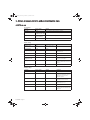
Packing
To improve waste treatment and facilitate recycling, separate the various packing components.
◗ The cardboard we use comprises over 50% of recycled cardboard.
◗ Sacks and bags are made of polyethylene.
◗ Packing materials are recyclable and bear the appropriate identification symbol
.
Material
Abbreviation
Symbol
number
Polyethylene terephthalate
PET
01
High-density polyethylene
HDPE
02
Polyvinyl chloride
PVC
03
Low-density polyethylene
LDPE
04
Polypropylene
PP
05
Polystyrene
PS
06
Follow all local regulations for the disposal of packing materials.
End of life
EATON Powerware® will process products at the end of their service life in compliance with local regulations.
EATON Powerware® works with companies in charge of collecting and eliminating our products at the end of their service life.
◗
Product
The product is made up of recyclable materials.
Dismantling and destruction must take place in compliance with all local regulations concerning waste.
At the end of its service life, the product must be transported to a processing centre for electrical and electronic waste.
◗
Battery
The product contains lead-acid batteries that must be processed according to applicable local regulations concerning
batteries.
The battery may be removed to comply with regulations and in view of correct disposal.
34008709EN/AA
- Page 3
ENGLISH
Thank you for selecting an EATON Powerware® product to protect your electrical equipment.
34008709EN_AA.fm Page 4 Mardi, 8. juillet 2008 4:28 16
Introduction
Pictograms
Important instructions that must always be followed.
Information, advice, help.
Visual indication.
Action.
Audio signal.
In the illustrations on the following pages, the symbols below are used:
LED off
LED on
LED blinking
34008709EN/AA
- Page 4
34008709EN_AA.fm Page 5 Mardi, 8. juillet 2008 4:28 16
Contents
Presentation
1.1
Standard positions ...................................................................................................................... 7
Tower position ................................................................................................................................ 7
1.2
Rack position ................................................................................................................................. 7
Rear panels................................................................................................................................... 8
PW9135 5000 / PW9135 6000 ...................................................................................................... 8
1.3
PW9135 EBM (optional battery module)........................................................................................ 8
Display and control panel ........................................................................................................... 9
1.4
Options ......................................................................................................................................... 9
Battery extensions for UPS backup times up to 80 minutes .......................................................... 9
2.
Installation
2.1
Unpacking and contents check ................................................................................................ 10
2.2
Internal batteries connection (Battery start-up)........................................................................ 10
2.3
Installation in tower position .....................................................................................................11
2.4
Installation in rack position ...................................................................................................... 12
Adjustment of the orientation of the logo and control panel......................................................... 12
UPS module rack mounting ......................................................................................................... 12
UPS or battery module rack mounting ......................................................................................... 13
2.5
Communication ports................................................................................................................ 14
Connection to the RS232 communication port ............................................................................ 14
Connection to the communication port by relays ......................................................................... 14
Remote Power Off communication port ....................................................................................... 15
Installation of communication cards............................................................................................. 15
2.6
Required protective devices and cable cross-sections ......................................................... 16
Recommended upstream protection............................................................................................ 16
Recommended downstream protection ....................................................................................... 16
3.
4.
2.7
Required cable cross-sections..................................................................................................... 16
Connection of input/output power cables to UPS terminals ................................................. 17
2.8
Connection of IEC cables to output receptacles .................................................................... 18
Operation
3.1
Initial start-up ............................................................................................................................. 19
3.2
Final start-up sequence............................................................................................................. 19
3.3
Operating modes ....................................................................................................................... 20
3.4
Operation on battery power ...................................................................................................... 21
3.5
Return on Normal AC source.................................................................................................... 21
3.6
UPS shutdown............................................................................................................................ 22
Access to measurements and personalisation data
4.1
Display organisation.................................................................................................................. 23
4.2
Access to measurements.......................................................................................................... 23
4.3
Access to UPS set-up and maintenance using the control panel ......................................... 23
4.4
UPS set-up.................................................................................................................................. 24
4.5
Maintenance ............................................................................................................................... 25
34008709EN/AA
- Page 5
ENGLISH
1.
34008709EN_AA.fm Page 6 Mardi, 8. juillet 2008 4:28 16
Contents
5.
6.
Troubleshooting
5.1
Troubleshooting LED (30)..........................................................................................................26
5.2
Troubleshooting not requiring EATON Powerware® after-sales support .............................26
5.3
Troubleshooting requiring EATON Powerware® after-sales support ....................................27
Life Cycle Monitoring (LCM)
6.1
Description..................................................................................................................................28
Secure your installation power continuity .....................................................................................28
Reset or disable LCM ...................................................................................................................28
7.
8.
34008709EN/AA
- Page 6
Maintenance
7.1
Hot swapping the power sub-module.......................................................................................29
7.2
Hot swapping the battery sub-module .....................................................................................29
Appendices
8.1
Technical specifications ............................................................................................................31
8.2
Glossary ......................................................................................................................................32
34008709EN_AA.fm Page 7 Mardi, 8. juillet 2008 4:28 16
1. Presentation
Tower position
Dimensions (H x W x D) in mm / Inches
PW9135 5000
444.5 x 131 x 700 /
17.5 x 5.16 x 27.56
PW9135 6000
444.5 x 131 x 700 /
17.5 x 5.16 x 27.56
PW9135 EBM
444.5 x 131 x 650 /
17.5 x 5.16 x 25.6
Weights in kg / lbs
PW9135 5000
57 / 125
PW9135 6000
57 / 125
PW9135 EBM
70 / 154
Rack position
Dimensions (H x W x D) in mm / Inches
PW9135 5000
131 x 444.5 x 700 /
5.16 x 17.5 x 27.56
PW9135 6000
131 x 444.5 x 700 /
5.16 x 17.5 x 27.56
PW9135 EBM
131 x 444.5 x 650 /
5.16 x 17.5 x 25.6
Weights in kg / lbs
PW9135 5000
57 / 125
PW9135 6000
57 / 125
PW9135 EBM
70 / 154
34008709EN/AA
- Page 7
ENGLISH
1.1 Standard positions
34008709EN_AA.fm Page 8 Mardi, 8. juillet 2008 4:28 16
1. Presentation
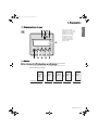
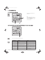
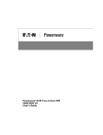
1.2 Rear panels
PW9135 5000 / PW9135 6000
SWITCHED
GROUP 2
SWITCHED
GROUP 1
BATTERY
CONNECTOR
180Vdc
DO NOT DISCONNECT
BATTERY CABLE
UNDER LOAD
CAUTION:
RS-232
CONTACTS
BATT. NO.
RPO
(1) Two groups of 2 programmable (10A)
outlets for connection of equipment
(2) Groups of 4 (10A) outlets for connection of
equipment
(3) Groups of 2 (16A) outlets for connection of
equipment
(4) 12A thermal switch
(5) 20A thermal switch
(6) 12A thermal switch
(7) Output terminal block
(8) Normal AC source terminal block
(9) Connector for additional battery module
(10) Slot for optional communication card
(12) USB communication port
(13) RS232 communication port
(14) Communication port by relay
(15) Connector for automatic detection of
battery module(s)
(16) Connector for Remote Power Off control
(RPO)
PW9135 EBM (optional battery module)
BATTERY
CONNECTOR
180Vdc
(17) Connectors for automatic detection of
battery module(s)
(18) Connectors for battery modules (to the
UPS or to the other battery modules)
(19) Battery circuit breaker
CAUTION:
DO NOT DISCONNECT
BATTERY CABLE
UNDER LOAD
BATT. NO.
CAUTION:
BATTERY BREAKER 50Adc
DO NOT DISCONNECT
BATTERY CABLE
UNDER LOAD
BATTERY
CONNECTOR
180Vdc
34008709EN/AA
- Page 8
34008709EN_AA.fm Page 9 Mardi, 8. juillet 2008 4:28 16
1. Presentation
ENGLISH
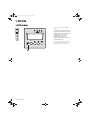
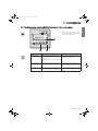
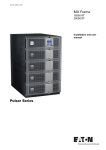
1.3 Display and control panel
(20) Load powered LED
(21) Operation on battery LED
(22) Operation on bypass LED
(23) Alphanumeric display
(24) Escape (cancel) button
(25) (26) Function buttons
(scroll down / scroll up)
(27) Enter (confirm) button
(29) UPS ON/OFF button
(30) Fault LED
esc
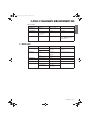
1.4 Options
Battery extensions for UPS backup times up to 80 minutes (at full load)
PW9135 offers a standard backup time of 4/5 minutes at full load.
To increase backup time, it is possible to connect PW9135 EBM modules to the UPSs.
Battery extensions for PW9135
PW9135
5000 /
6000
PW9135
EBM
PW9135
EBM
PW9135
EBM
PW9135
EBM
PW9135 5000 :
5 mim
22 mim
41 mim
62 mim
83 mim
PW9135 6000 :
4 mim
17 mim
33 mim
50 mim
67 mim
34008709EN/AA
- Page 9
34008709EN_AA.fm Page 10 Mardi, 8. juillet 2008 4:28 16
2. Installation
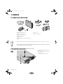
2.1 Unpacking and contents check
(40) PW9135 5000 or 6000 UPS.
(46) Screw driver.
(41) Two sets of tower stands.
(49) 4 IEC 10A output cables.
(42) RS232 communications cable.
(43) Product documentation.
(44) 4 cable lockers.
(45) Telescopic rails for rack enclosure with mounting
hardware.
Packaging must be destroyed according to waste management standards. Recycling icons are displayed for easy selection.
A dangerous voltage is present inside the power module and the battery module. Any operations to be carried out
on these modules must be done so by qualified staff.
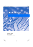
2.2 Internal battery connection (Battery start-up)
1 - Remove the two fixing screws (59) to free
the battery connector.
2 - Push the battery connector so that you can
read "Connected".
3 - Secure the two fixing screws (59).
34008709EN/AA
- Page 10
34008709EN_AA.fm Page 11 Mardi, 8. juillet 2008 4:28 16
2. Installation
2.3 Installation in tower position
ENGLISH
Follow steps 1 to 3 to adjust the tower stands for the upright position.
Always keep 150 mm free space behind the UPS rear panel.
The distance between the tower stands should be 450 mm.
34008709EN/AA
- Page 11
34008709EN_AA.fm Page 12 Mardi, 8. juillet 2008 4:28 16
2. Installation
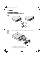
2.4 Installation in rack position
Adjustment of the orientation of the logo and control panel
UPS module rack mounting
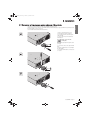
PW9135 is very heavy. To ease its rack integration, we strongly recommend to remove the battery tray as shown below:
1 - Remove the 6 fixing screws to free the main front panel bezel.
2 - Place the front panel above the UPS.
3 - Remove the 4 fixing screws on the right side to free the battery sub-module.
4 - Pull the battery sub-module slightly, then lift it to extract it.
34008709EN/AA
- Page 12
34008709EN_AA.fm Page 13 Mardi, 8. juillet 2008 4:28 16
2. Installation
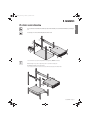
It is not allowed to install the UPS or battery module in a hermetically closed environment without any exchange of
air.
Follow steps 1 to 4 for rack mounting the UPS onto the rails.
The rails and the necessary mounting hardware are supplied by EATON Powerware®.
Note for step 1: it is possible to adjust the position of both front mounting ears.
Rear bracket system (included with rail kits)
To be used if you need to move the rack enclosure with UPS already rack-mounted inside.
34008709EN/AA
- Page 13
ENGLISH
UPS or battery module rack mounting
34008709EN_AA.fm Page 14 Mardi, 8. juillet 2008 4:28 16
2. Installation
2.5 Communication ports
PW9135 provides 3 communication methods that can be used simultaneously:
®
◗ 2 COM ports provide RS232 or USB communications using EATON Powerware SHUT protocol. Compatible with most
power management software applications. Please, note that both ports cannot be used at the same time.
◗ The output contact port is used for basic signaling or for protection of IT systems like IBM iSeries (formerly AS400) and more.
®
◗ The slot is compatible with EATON Powerware communication card (check www.powerware.com web site for the
complete list of compatible cards).
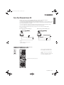
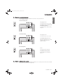
Connection to the RS232 communication port
SWITCHED
GROUP 2
1 - Connect the RS232 (42) communications
cable to the serial port on the computer
equipment.
SWITCHED
GROUP 1
2 - Connect the other end of the
communication cable (42) to the RS232 (13)
communications port on the UPS.
The UPS can now communicate with various
EATON Powerware® power management
application software.
BATTERY
CONNECTOR
180Vdc
DO NOT DISCONNECT
BATTERY CABLE
UNDER LOAD
CAUTION:
RS-232
CONTACTS
BATT. NO.
RPO
Connection to the communication port by relays (14)
(see page 8)
◗
5
4
9
3
8
2
7
◗
1
14
6
◗
◗
◗
n.c.
n.o.
n.o.
n.o.
n.o.
common
Pin 1, 2: not used,
Pin 3: remote Power Off signal (5 to 27 V DC, 10 mA max),
Pin 4: operation on mains (not on battery),
Pin 5: user common,
◗
Pin 6: operation on automatic by-pass,
Pin 7: low battery,
◗
Pin 8: load protected,
◗
Pin 9: operation on battery.
n.o.: contact normally open.
n.c.: contact normally closed.
When the status is active, the contact between the common (Pin 5) and the relevant information pin is closed.
Output relays specifications
◗ Voltage: 48 V DC max,
◗ Current: 2 A max,
◗ Power: 62,5 VA, 30 W.
Example: for 48 V DC, Imax=625 mA
34008709EN/AA
- Page 14
34008709EN_AA.fm Page 15 Mardi, 8. juillet 2008 4:28 16
2. Installation
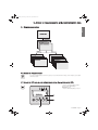
Remote Power Off communication port (16)
Installation of a Remote Power Off function must be carried out in compliance with applicable regulations.
In order to fully de-energize devices and PW9135 with the RPO port, it is necessary:
◗ to use a two-position switch (Normally Open or Closed contact should be held more than 1 second to be taken into account).
(1)
◗ to connect to this RPO switch a device that allows to trip all breaker(s) located upstream
and downstream(2) PW9135.
This can be achieved by means of a shunt trip.
(1) : If not, the output devices could be powered again through static switch when the two-position switch is released.
(2) : If not, the output devices will remain powered several seconds after the RPO activation.
Please, notice that the internal batteries will remain connected to the power sub-module after RPO activation.
The cable is not included.
Remote power off contact normally open
Remote power off contact normally closed
RJ12 (6p6c)
RJ12 (6p6c)
654321
654321
5 V DC to 27 V DC
5 V DC to 27 V DC
◗
Signal:
- activation voltage: 5 V DC to 27 V DC.
- current: 10 mA max.
Installation of communication cards (optional)
SWITCHED
GROUP 2
It is not necessary to shutdown the UPS
before installing a communications card.
SWITCHED
GROUP 1
1 - Remove the slot cover secured by two
screws.
2 - Insert the communications card in the slot.
3 - Secure the card with both screws.
BATTERY
CONNECTOR
180Vdc
DO NOT DISCONNECT
BATTERY CABLE
UNDER LOAD
CAUTION:
Communication card (restricted access)
RS-232
CONTACTS
BATT. NO.
RPO
34008709EN/AA
- Page 15
ENGLISH
(see page 8)
34008709EN_AA.fm Page 16 Mardi, 8. juillet 2008 4:28 16
2. Installation
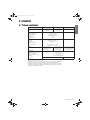
2.6 Required protective devices and cable cross-sections
Recommended upstream protection
UPS power rating
Upstream circuit breaker
PW9135 5000
D curve - 32A
PW9135 6000
D curve - 32A
The indicated protection ensures
discrimination for each output circuit
downstream of the UPS.
If these recommendations are not followed,
protection discrimination is not achieved and
may result in a potential power interruption to
the connected devices.
2 poles circuit breaker
L
N
G
N
To UPS Normal AC source
L
Recommended downstream protection
UPS power rating
Downstream circuit breaker
PW9135 5000
Z curve - 10A
C curve - 4A
PW9135 6000
Z curve - 10A
C curve - 6A
The indicated protection ensures
discrimination for each output circuit
downstream of the UPS.
If these recommendations are not followed,
protection discrimination is not achieved and
may result in a potential power interruption to
the connected devices.
Required cable cross-sections
◗
2
2
Terminal-block cable capacity: 6 mm , solid or stranded wire (maximum 8 mm or AWG 8).
2
2
◗ Capacity for earthing conductor: 6 mm , solid or stranded wire (maximum 8 mm or AWG 8).
34008709EN/AA
- Page 16
34008709EN_AA.fm Page 17 Mardi, 8. juillet 2008 4:28 16
2. Installation
◗
This type of connection must be carried out by qualified electrical personnel.
Before carrying out any connection, check that the battery circuit breaker (19) (see page 8) and that the upstream protection
device (Normal AC source) is open ("0").
◗ Use included insulated ferrules with stranded wires.
◗
1 - Remove the terminal block cover (2
screws) with the included screwdriver.
2 - Insert the Normal AC cable through the
cable gland (8).
3 - Connect the 3 wires to the Normal AC
terminal block.
Always connect first the
earthing wire.
4 - Insert the output cable through the cable
gland (7).
5 - Connect the 3 wires to the output terminal
block.
6 - Refit the terminal block cover and tighten
the cable glands.
7 - Secure the terminal block cover by means
of 2 screws.
34008709EN/AA
- Page 17
ENGLISH
2.7 Connection of input/output power cables on UPS terminals
34008709EN_AA.fm Page 18 Mardi, 8. juillet 2008 4:28 16
2. Installation
2.8 Connection of IEC cables to output receptacles
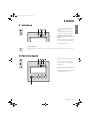
1 - Connect the equipments to the UPS using
the cables (49).
It is preferable to connect the priority
equipments to the four outlets (2) and the non
priority equipments to the four outlets (1) that
can be programmed in pairs (1 and 2).
Connect any high-power devices to the 16 A
outlet (3)
To program shutdown of outlets (2) during
operation on battery power and thus optimise
the available backup time, the EATON
Powerware® communication software is
required.
2 - Fit the connection securing system (44)
that prevents the plugs from being pulled out
accidentally.
34008709EN/AA
- Page 18
34008709EN_AA.fm Page 19 Mardi, 8. juillet 2008 4:28 16
3. Operation
1 - Check that the battery switch (60) (see
section 2.2, page 10) on top cover is
connected.
2 - Set the upstream circuit breaker (not
included) to the "ON/OFF" position (ON).
The equipments are powered via the
Normal AC source, but not protected by
the UPS.
Batteries are recharging, an 8 hour recharge
period is necessary to get full backup time.
LEDs (20) and (22) are ON.
UPS personalisation
If UPS personalisation is desired, it is advised to enter the personalisation mode at this time (see the 4.4 "Personalisation"
section).
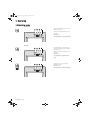
3.2 Final start-up sequence
3- Press the "ON/OFF" button (29) more than
3s.
The buzzer beeps once, and after UPS
internal test sequence, the LED (20) is ON.
LED (20) is ON.
The equipments are protected by the UPS.
If LED (30) is ON, an alarm has occurred (see
the "troubleshooting" section).
esc
34008709EN/AA
- Page 19
ENGLISH
3.1 Initial start-up
34008709EN_AA.fm Page 20 Mardi, 8. juillet 2008 4:28 16
3. Operation
3.3 Operating modes
Normal mode
This is the standard operating mode, set by
default in the factory.
Under normal condition (Normal AC source
available):
LED (20) is ON.
The equipments are protected by the UPS.
Eco mode
The main advantage of the Eco mode (see
glossary) is that it reduces the consumption
of electrical power.
Under normal condition (Normal AC source
available):
LED (20) is ON.
The equipments are supplied in ECO
mode.
If normal AC source is out of tolerance:
LED (20), is flashing.
LED (30), is ON.
The equipments are protected by the UPS.
34008709EN/AA
- Page 20
34008709EN_AA.fm Page 21 Mardi, 8. juillet 2008 4:28 16
3. Operation
3.4 Operation on battery power
ENGLISH
When the Normal AC source is not available, the load continues to be protected by the UPS.
Power is supplied by the battery.
Transfer to battery power
LEDs (20), (21) are ON.
The audio alarm beeps every 10 seconds.
The equipments are protected by the UPS
and supplied by the battery.
The display indicates the battery remaining
backup time.
Low battery warning
LEDs (20), (21) are ON.
The audio alarm beeps every 3 seconds.
The remaining battery power is low.
Shut down all applications on the connected
equipment because automatic UPS
shutdown is imminent.
End of backup time
No LED
The audio alarm beeps continuously.
The equipments are not powered.
The UPS displays "End of backup time
Battery low".
3.5 Return on Normal AC source
After an outage, the UPS restarts automatically when Normal AC source is restored (unless this function has been disabled
via UPS personalisation) and the load is supplied again.
34008709EN/AA
- Page 21
34008709EN_AA.fm Page 22 Mardi, 8. juillet 2008 4:28 16
3. Operation
3.6 UPS shutdown
1 - Press the "ON/OFF" button (29) more
than 3s.
The buzzer beeps once, and the load is no
longer protected by the UPS. It is powered
via the Normal AC source. If the UPS is set
in frequency converter mode, the
equipments will not be powered.
If the Normal AC source is out of
tolerance, the UPS will generate a 10ms
output calibrated break.
esc
34008709EN/AA
- Page 22
2 - For a full shutdown of UPS and connected
load, the upstream circuit breaker (not
included) should be set to the "0" position.
34008709EN_AA.fm Page 23 Mercredi, 9. juillet 2008 9:57 09
4. Access to measurements and personalisation data
ENGLISH
4.1 Display organisation
4.2 Access to measurements
Press the scroll button (26) (see section 1.3, page 9) to access measurements for voltage, current, frequency, power output
and battery capacity.
4.3 Access to UPS set-up and maintenance using the control panel (23)
◗
Press the scroll button (25) a number of
times to point the UPS set-up or
Maintenance menu
◗ Press the Enter button (27) to get access.
esc
34008709EN/AA
- Page 23
34008709EN_AA.fm Page 24 Mardi, 8. juillet 2008 4:28 16
4. Access to measurements and personalisation data
4.4 UPS set-up
Local settings
Function
Factory setting
Options
Language
English
French, German, Italian, Portuguese, Spanish
Date / Time Format
International
(DD-MM-YYYY/HH :MM)
US (MM-DD-YYYY/HH:MM AM/PM)
Date / Time Change
GMT + 1
(Continental Europe)
MM-DD-YYYY/HH :MM adjustable
Audible Alarm
Yes
No
Function
Factory setting
Options
Output Voltage
230 V
200 V / 208 V / 220 V /
240 V / 250 V
Freq Converter
Disable
Enable
Output Frequency
50 Hz
60 Hz
User selectable under frequencyconverter mode
Eco Mode
Disable
Enable
See glossary
Slew Rate
1 Hz / sec.
0.5 Hz / sec.
Bypass Transfer
If bypass Ac nok?
Yes
No
Transfer to bypass if Normal AC
source is out of tolerance
Interrupt Time
10 ms
20 ms, ...... , 200 ms
Break time calibration during load
transfer on Normal AC source out of
tolerance
Overload Prealarm
105 %
40 %, 50 %, 70 %
Alarm if threshold is overrun
Function
Factory setting
Options
Comments
Cold Start
Disable
Enable
Start on battery
Forced Reboot
Enable
Disable
Enables automatic restart of the
system even if Normal AC source is
restored before the end of the
shutdown sequence
Auto Restart
Enable
Disable
UPS restarts automatically when
Normal AC source is restored
Energy Saving
Disable
Enable
Automatic shutdown on battery if
output load level < 10 %
Sleep Mode
Enable
Disable
Remote Command
Enable
Disable
Output settings
Comments
ON/OFF settings
34008709EN/AA
- Page 24
Enables consideration of shutdown
or restart orders from software to be
authorised
34008709EN_AA.fm Page 25 Mardi, 8. juillet 2008 4:28 16
4. Access to measurements and personalisation data
Battery settings
Factory setting
Options
Comments
Auto Battery Test
Everyweek
No test / everyday /
everyweek /everymonth
Low Batt Warning
20%
0 to 100%
1% increment
User Batt Settings
UPS reads number of
battery modules
connected
From 0 to 95 Ah
5 Ah increment
Deep Disch Protect
Yes
No
Protection against deep discharge.
If disable, EATON Powerware®
warranty will be void
Function
Sub-Function
Option / Display
Comments
Model
Power Module
SN: xxxxxxxxx
SOFT: xxx
Serial number
Soft version
Read
Description
Date Hour
Alarm xxx
10 alarms can be stored
automatically
Erase
No / Yes
Manual Batt Test
Manual Battery Test
No / Yes
Led & Buzzer Test
Led & Buzzer Test
No / Yes
Life Cycle Monitoring
LCM
Enable / Disable
Statistics
Auto Statistics
Statistics
Custom Statistics
Reset Date ?
Are you sure ?
ENGLISH
Function
4.5 Maintenance
Frame
Alarm History
Life cycling monitoring alarms
34008709EN/AA
- Page 25
34008709EN_AA.fm Page 26 Mardi, 8. juillet 2008 4:28 16
5. Troubleshooting
5.1 Troubleshooting LED (30)
Press the escape button (24) to stop the
audible alarm.
Note :
In case of "MULTIPLE FAULT", press the
"Enter" button (27) and the scroll button (25)
to get access to further details.
In case of "LCM WARNING", refer to LCM
section (see section 6).
esc
5.2 Troubleshooting not requiring EATON Powerware® after-sales support
esc
Press the "Enter" button (27) to display the details below :
34008709EN/AA
- Page 26
Displayed details
Signification
Correction
NO BATTERY
The battery is incorrectly connected
Check battery connections
I/O BAD CONNECTION
AC source is not connected to the correct
terminals
Check AC wiring
NO POWER MODULE
The power sub-module is not inserted
Check power sub-module connections (see
section 7.1)
NO BATTERY MODULE
The battery sub-module is incorrectly
connected
Check battery connections (see section 7.2)
INV THERM OVERLOAD
The UPS shuts down automatically because
of a major overload.
Check the power drawn by the connected
devices and disconnect any non-priority
devices.
INVERT LIMITATION
Short circuit conditions on output devices
Check the installation at the UPS output
(wiring, fault equipment)
34008709EN_AA.fm Page 27 Mardi, 8. juillet 2008 4:28 16
5. Troubleshooting
Note: In case of multiple fault, press the
"Enter" button (27) and the scroll button (25)
to get access to further details.
esc
Display
Signification
Correction
POWER MODULE
FAULT
Internal power sub-module fault detected.
Use "Enter" button (27) to display details.
Call the after-sales support department.
Follow the power sub-module replacement
procedure (see section 7.1)
In Parallel :
See the note below to start the other UPS
alone.
BATT MODULE FAULT
Battery fault detected during the battery test.
Use "Enter" button (27) to display details.
Call the after-sales support department.
Follow the battery sub-module and battery
module replacement procedure (see section
7.2)
FRAME FAULT
Internal chassis fault detected.
Use "Enter" button (27) to display details.
Call the after-sales support department.
34008709EN/AA
- Page 27
ENGLISH
5.3 Troubleshooting requiring EATON Powerware® after-sales support
34008709EN_AA.fm Page 28 Mardi, 8. juillet 2008 4:28 16
6. Life Cycle Monitoring (LCM)
6.1 Description
This function, embedded in the UPS, displays messages, on screen and communication channels, at every important
stage of the UPS’s life, allowing you to:
Press the "Enter" button (27) to display LCM
warning details.
esc
Secure your installation power continuity
Anticipate maintenance actions thanks to automatically displayed warnings while displaying automatic warnings when
maintenance actions need to be planned :
LCM warning details
Signification
BATTERY CHECK RECOMMENDED
Battery is approaching its reliability end of life. Risk to reduce dramatically
backup time
Reset or disable LCM
In case of any LCM messages displayed:
◗ For temporary reset: press the escape button (24) more than 3 seconds, into Status and Alarm screen, to cancel temporary
the alarm status.
The alert will be repeated twice each 30 days.
◗ For permanent reset: press the enter button (27) more than 3 seconds, into LCM warning screen, to cancel permanently this
LCM event.
At any time:
To Disable all LCM messages select "disable all" ,into LCM menu with LCD navigation.
Be careful: you will not be aware of any LCM events that can happen on the UPS if you disable all LCM messages.
34008709EN/AA
- Page 28
34008709EN_AA.fm Page 29 Mardi, 8. juillet 2008 4:28 16
7. Maintenance
7.1 Hot swapping the power sub-module
ENGLISH
This operation must be carried out by qualified electrical personnel only.
This operation can be performed without interrupting the equipments.
Disconnecting the power sub-module :
1 - Remove the 6 fixing screws to free the
main front panel bezel.
2 - Place the front panel above the UPS.
3 - Remove the 4 fixing screws on the left side
to free the power sub-module.
4 - Withdraw the power sub-module.
Reconnecting the power sub-module :
◗
Carry out the above instructions in reverse order.
◗
Replace the faulty power sub-module by another one with same power rating (PW9135 5000 or PW9135 6000).
7.2 Hot swapping the battery sub-module
◗
Caution: a battery can cause electrocution and high short circuit currents.
◗
Servicing of batteries should be performed or supervised by personel knowledgeable of batteries and the required
precautions. Keep unauthorized personel away from batteries.
◗ Remove watches, rings, bracelets and all other metal objects from the hands and arms,
◗ Use tools with an insulated handle.
◗ When replacing batteries, replace with the same number of the BB/HR5.5-12 batteries.
This operation can be performed without interrupting the equipments.
Disconnecting the battery sub-module :
1 - Remove the 6 fixing screws to free the
main front panel bezel.
2 - Place the front panel above the UPS.
3 - Remove the 4 fixing screws on the right
side to free the battery sub-module.
4 - Pull the battery sub-module slightly, then
lift it to extract it.
34008709EN/AA
- Page 29
34008709EN_AA.fm Page 30 Mardi, 8. juillet 2008 4:28 16
7. Maintenance
Reconnecting the battery sub-module :
Carry out the above instructions in reverse order.
◗
34008709EN/AA
- Page 30
To ensure safety and high performance, use only batteries supplied by EATON Powerware®.
34008709EN_AA.fm Page 31 Mardi, 8. juillet 2008 4:28 16
8. Appendices
Output power
Electrical supply network
Rated input voltage
◗ Input voltage range
◗ Frequency
◗ Power factor
◗ Leakage current
◗
Load output
Voltage
◗ Frequency
◗ Harmonic distortion
◗ Overload capacity
◗
Battery
Environment
Operating temperature range
◗ Relative humidity
◗ Storage temperature range
◗ Altitude
◗
◗
Noise level
PW9135 5000(5)
PW9135 6000(6)
5000 VA /
3500 W
6000 VA (1) /
4200 W
PW9135 EBM(7)
Single phase 230 V
120 / 156 V to 280 V (2)
50/60 Hz (autoselection)
> 0.99
7 mA max.
Single phase 230 V ±3% (3)
50/60 Hz ±0,5% (4)
< 3%
105% continuous, 110% 2min,
125% 1min, > 150% 0.5s
15 x 12V - 5 Ah,
sealed lead acid,
maintenance free
15 x 12V - 5 Ah,
sealed lead acid,
maintenance free
Two 15 x 12 V - 5 Ah
strings, sealed lead acid,
maintenance free
0°C to 40°C
20% to 90% (non-condensing)
-25°C to 40°C
0 to 1000 m without derating
< 45 dBA
(1) If the output voltage is 200V, the output power is 5400VA / 3780W.
(2) Values for 70% / 100% of UPS output.
(3) Programmable: 200V / 208V / 220V / 230V / 240V / 250V using the UPS Config software.
(4) Frequency-converter mode is programmable using the UPS Config software.
(5) Model list: PW9135G5000-XL3UHW, PW9135G5000-XL3U, PW9135G5000-XL3UEU.
(6) Model list: PW9135G6000-XL3UHW, PW9135G6000-XL3U, PW9135G6000-XL3UEU.
(7) Model list: PW9135G6000-EBM3U.
34008709EN/AA
- Page 31
ENGLISH
8.1 Technical specifications
34008709EN_AA.fm Page 32 Mardi, 8. juillet 2008 4:28 16
8. Appendices
8.2 Glossary
34008709EN/AA
Backup time
Time that the connected equipments can operate on battery power.
Bypass AC source
Source supplying the bypass line. The equipments can be transferred to the bypass line if an
overload occurs on the UPS output, for maintenance or in the event of a malfunction.
ECO mode
Operating mode by which the equipments are supplied directly by the AC source if it is within the
tolerances defined by the user. This mode reduces the consumption of electrical power.
Equipments
Devices or systems connected to the UPS output.
Frequency converter
Operating mode used to convert the AC-power frequency between the UPS input and output
(50 Hz -> 60 Hz or 60 Hz -> 50 Hz).
Low-battery warning
This is a battery-voltage level indicating that battery power is low and that the user must take
action in light of the imminent break in the supply of power to the load.
Manual bypass
Rotary switch controlled by the user, used to connect the equipments directly to the AC source.
Transfer of the equipments to the manual bypass enables UPS maintenance without interrupting
the supply of power to the connected equipments.
Normal AC source
Normal source of power for the UPS.
Normal (double
conversion) mode
The normal UPS operating mode in which the AC source supplies the UPS which in turn supplies
the connected equipments (after electronic double conversion).
Personalisation
It is possible to modify certain UPS parameters set in the factory. Certain UPS functions can also
be modified by the EATON powerware® power management products to better suit user needs.
Programmable
outlets
These outlets can be automatically shut down during operation on battery power (shutdown time
delays can be programmed with the EATON powerware® power management products). The
UPS has two sets of two programmable outlets.
Relay contacts
Contacts supplying information to the user in forme of signals.
UPS
Uninterruptible Power System.
- Page 32
34008709EN_AA.fm Page 33 Mardi, 8. juillet 2008 4:28 16
34008709EN/AA
- Page 33
34008709EN_AA.fm Page 34 Mardi, 8. juillet 2008 4:28 16
www.powerware.com
34008709EN/AA