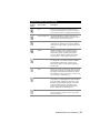
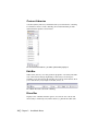
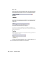
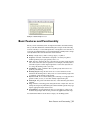
1
AutoSketch 10
Getting Started
®
October 2008
© 2008 Autodesk, Inc. All rights reserved. Except as otherwise permitted by Autodesk, Inc., this publication, or parts thereof, may
not be reproduced in any form, by any method, for any purpose.
Certain materials included in this publication are reprinted with the permission of the copyright holder.
Trademarks
The following are registered trademarks or trademarks of Autodesk, Inc., in the USA and other countries: 3DEC (design/logo),
3December, 3December.com, 3ds Max, ADI, Alias, Alias (swirl design/logo), AliasStudio, Alias|Wavefront (design/logo), ATC, AUGI,
AutoCAD, AutoCAD Learning Assistance, AutoCAD LT, AutoCAD Simulator, AutoCAD SQL Extension, AutoCAD SQL Interface,
Autodesk, Autodesk Envision, Autodesk Insight, Autodesk Intent, Autodesk Inventor, Autodesk Map, Autodesk MapGuide, Autodesk
Streamline, AutoLISP, AutoSnap, AutoSketch, AutoTrack, Backdraft, Built with ObjectARX (logo), Burn, Buzzsaw, CAiCE, Can You
Imagine, Character Studio, Cinestream, Civil 3D, Cleaner, Cleaner Central, ClearScale, Colour Warper, Combustion, Communication
Specification, Constructware, Content Explorer, Create>what's>Next> (design/logo), Dancing Baby (image), DesignCenter, Design
Doctor, Designer's Toolkit, DesignKids, DesignProf, DesignServer, DesignStudio, Design|Studio (design/logo), Design Web Format,
DWF, DWG, DWG (logo), DWG Extreme, DWG TrueConvert, DWG TrueView, DXF, Ecotect, Exposure, Extending the Design Team,
FBX, Filmbox, FMDesktop, Freewheel, GDX Driver, Gmax, Green Building Studio, Heads-up Design, Heidi, HumanIK, IDEA Server, idrop, ImageModeler, iMOUT, Incinerator, Inventor, Inventor LT, Kaydara, Kaydara (design/logo), Kynapse, Kynogon, LandXplorer,
LocationLogic, Lustre, Matchmover, Maya, Mechanical Desktop, MotionBuilder, Movimento, Mudbox, NavisWorks, ObjectARX,
ObjectDBX, Open Reality, Opticore, Opticore Opus, PolarSnap, PortfolioWall, Powered with Autodesk Technology, Productstream,
ProjectPoint, ProMaterials, RasterDWG, Reactor, RealDWG, Real-time Roto, REALVIZ, Recognize, Render Queue, Retimer,Reveal, Revit,
Showcase, ShowMotion, SketchBook, SteeringWheels, Stitcher, StudioTools, Topobase, Toxik, TrustedDWG, ViewCube, Visual, Visual
Construction, Visual Drainage, Visual Landscape, Visual Survey, Visual Toolbox, Visual LISP, Voice Reality, Volo, Vtour, Wiretap, and
WiretapCentral.
The following are registered trademarks or trademarks of Autodesk Canada Co. in the USA and/or Canada and other countries:
Backburner, Discreet, Fire, Flame, Flint, Frost, Inferno, Multi-Master Editing, River, Smoke, Sparks, Stone, and Wire.
The following are registered trademarks or trademarks of Moldflow Corp. in the USA and/or other countries: Moldflow
MPA, MPA (design/logo), Moldflow Plastics Advisers, MPI, MPI (design/logo), Moldflow Plastics Insight, MPX, MPX (design/logo),
Moldflow Plastics Xpert.
All other brand names, product names or trademarks belong to their respective holders.
Disclaimer
THIS PUBLICATION AND THE INFORMATION CONTAINED HEREIN IS MADE AVAILABLE BY AUTODESK, INC. "AS IS." AUTODESK, INC.,
DISCLAIMS ALL WARRANTIES, EITHER EXPRESS OR IMPLIED, INCLUDING BUT NOT LIMITED TO ANY IMPLIED WARRANTIES OF
MERCHANTABILITY OR FITNESS FOR A PARTICULAR PURPOSE REGARDING THESE MATERIALS.
Published by:
Autodesk, Inc.
111 Mclnnis Parkway
San Rafael, CA 94903, USA
Contents
Chapter 1
Installation .
.
.
.
.
.
.
.
Contents of the AutoSketch Package
System Requirements . . . . .
Install AutoSketch . . . . . .
Register AutoSketch . . . . . .
Repair AutoSketch . . . . . .
Uninstall AutoSketch . . . . .
Chapter 2
.
.
.
.
.
.
.
.
.
.
.
.
.
.
.
.
.
.
.
.
.
Make the Transition from Paper to CAD
Draw to Scale . . . . . .
Organize Drawing Information
Draw Efficiently . . . . .
Draw Accurately . . . . .
View Your Drawing . . . .
Modify Your Drawing . . .
Use Standard Symbols . . .
Create Dimensions and Text .
.
.
.
.
.
.
.
.
.
.
.
.
.
.
.
.
.
.
.
.
.
.
.
.
.
.
.
.
.
.
.
.
.
.
.
.
.
.
.
.
.
.
.
.
.
.
.
.
.
.
.
.
.
.
.
.
.
.
.
.
.
.
.
.
.
.
.
.
.
.
.
.
.
.
.
.
.
.
.
.
.
.
.
.
.
.
.
.
.
.
.
.
.
.
.
.
.
.
.
.
.
.
.
.
.
.
.
.
.
.
.
.
.
.
.
.
.
.
.
.
.
.
.
.
.
.
.
.
.
.
.
.
.
.
.
.
.
.
.
.
.
.
.
.
.
.
.
.
.
.
.
.
.
.
.
.
.
.
.2
.2
.3
.3
.4
.4
.
.
.
.
.
.
.
.
.
1
7
.8
.9
10
11
12
13
14
15
iii
Chapter 3
iv
|
Contents
.
.
.
.
Introduction . . . . . . . . . . . . . . .
Start AutoSketch . . . . . . . . . . . . . .
Use the Start Up Dialog Box to Create or Open a Drawing .
Start a Drawing or Choose a Wizard (Wizard Tab) .
Choose a Template (Template Tab) . . . . . .
Open an Existing Drawing (Open Tab) . . . . .
Understand the User Interface . . . . . . . . .
Drawing Window. . . . . . . . . . . .
All-In-One Toolbar . . . . . . . . . . .
Content Librarian . . . . . . . . . . .
Edit Bar . . . . . . . . . . . . . . .
Menu Bar . . . . . . . . . . . . . .
Property Bar . . . . . . . . . . . . .
Status Bar . . . . . . . . . . . . . .
Title Bar . . . . . . . . . . . . . . .
Toolbars. . . . . . . . . . . . . . .
Tooltips . . . . . . . . . . . . . . .
Basic Features and Functionality . . . . . . . . .
Entities . . . . . . . . . . . . . . .
Properties . . . . . . . . . . . . . .
Scale . . . . . . . . . . . . . . . .
Coordinates . . . . . . . . . . . . .
Drawing Origin . . . . . . . . . . . .
Reference Grid. . . . . . . . . . . . .
Grid Origin . . . . . . . . . . . . . .
Snap . . . . . . . . . . . . . . . .
Lock Modifier . . . . . . . . . . . . .
AutoSketch Basics
.
.
.
.
.
.
.
.
.
.
.
.
.
.
.
.
.
.
.
.
.
.
.
.
.
.
.
.
.
.
.
.
.
.
.
.
.
.
.
.
.
.
.
.
.
.
.
.
.
.
.
.
.
.
.
.
.
.
.
.
.
.
.
.
.
.
.
.
.
.
.
.
.
.
.
.
.
.
.
.
.
.
.
.
.
.
.
.
.
.
.
Appendix — Drawings Created with AutoSketch
.
.
.
.
. 17
.
.
.
.
.
.
.
.
.
.
.
.
.
.
.
.
.
.
.
.
.
.
.
.
.
.
.
18
18
18
19
21
22
23
23
25
28
28
28
29
29
30
30
30
31
32
33
34
34
35
36
37
37
38
. 39
1
Installation
This chapter tells you how to install AutoSketch®on
In this chapter
your computer. After you install the software, view the
■ Contents of the AutoSketch
Package
Readme (click Read Me on the Help menu). The Readme
■ System Requirements
contains important information that was compiled after
■ Install AutoSketch
this guide was printed.
■ Register AutoSketch
■ Repair AutoSketch
For step-by-step instructions about learning the
■ Repair AutoSketch
product, read the entire Getting Started guide. You can
■ Uninstall AutoSketch
find a PDF version of this guide in the following
location (“C” is the installation drive letter):
C:\Program Files\Autodesk\AutoSketch10
1
Contents of the AutoSketch Package
AutoSketch includes the following:
■
■
■
■
■
■
AutoSketch disc
AutoSketch Getting Started (this guide)
Create and Trim Entities (online tutorial)
Create a Birdhouse Drawing (online tutorial)
Create and Office Layout Drawing (online tutorial)
Advanced Exercises (online tutorial)
System Requirements
Before you install AutoSketch, make sure that your computer meets the
minimum system requirements.
Hardware and software requirements
2
|
Hardware/Software
Requirement
Operating system
Windows®Vista or
Windows®XP Service Pack 2, 32bit
Web browser
Microsoft®Internet Explorer 6.0
with Service Pack 1 (or later)
Processor
Intel® Pentium® IV or
AMD Athlon™2.2 GHz or greater
RAM
Windows Vista - 1 GB
Windows XP - 512 MB
Video
800 x 600 (minimum) with True
Color
Hard disk
200 MB
Pointing device
Mouse, trackball, or other
compatible pointing device
CD-ROM or DVD drive
Any speed (for installation only)
Chapter 1
Installation
Notes
Requires a Windows-supported
display adapter
Install AutoSketch
This section explains how to install AutoSketch on a stand-alone computer.
To install AutoSketch
1 Insert the AutoSketch CD into your CD-ROM drive.
2 Follow the installation prompts that are displayed.
If installation did not begin when you inserted the AutoSketch CD into your
CD-ROM drive, Autorun may be turned off on your machine.
To install AutoSketch if Autorun is turned off
1 Insert the AutoSketch CD into your CD-ROM drive.
2 On the Start menu (Windows), click Run.
3 In the Run dialog box, enter <CD drive letter>:\Setup.exe and click OK.
4 Follow the installation prompts.
Congratulations! You have successfully installed AutoSketch. You are now
ready to register your product and start using the program.
Register AutoSketch
Registering AutoSketch makes you eligible for technical support and for early
notification of new product releases.
To register AutoSketch
1 On the Start menu (Windows), click All Programs (or Programs) ➤
Autodesk AutoSketch 10.
2 In the AutoSketch Product Registration wizard, select Register Now, and
then click Next.
3 Follow the on-screen instructions.
Install AutoSketch
|
3
Repair AutoSketch
If you accidentally delete or alter files that are required by AutoSketch, it
might not perform correctly. You can attempt to repair AutoSketch.
To repair AutoSketch
1 In the Control Panel (Windows), start Add or Remove Programs.
2 In the Add or Remove Programs window, select AutoSketch Release 10,
and then click Change.
3 In the Setup wizard, Application Maintenance page, select the Repair
option, and then click Next.
4 On the Ready to Repair the Application page, click Finish.
5 If prompted, restart your computer.
Uninstall AutoSketch
When you uninstall AutoSketch, all components are removed from the
computer.
Note Uninstalling the application does not automatically delete drawing files
you have created. You can delete those files manually.
To uninstall AutoSketch
1 In the Control Panel (Windows), start Add or Remove Programs.
2 In the Add or Remove Programs window, select AutoSketch Release10, and
then click Remove.
3 In the message box that is displayed, click Yes to remove AutoSketch.
4 If prompted, restart your computer.
4
|
Chapter 1
Installation
Uninstall AutoSketch
|
5
6
Make the Transition from
Paper to CAD
2
With your decision to use AutoSketch®, you have
In this chapter
entered the world of computer-aided design (CAD).
■ Draw to Scale
AutoSketch makes your drawings more precise and you
more productive than you have been using paper as
your design format.
This chapter explains how you can take your drafting
■ Organize Drawing Information
■ Draw Efficiently
■ Draw Accurately
■ View Your Drawing
■ Modify Your Drawing
■ Create Dimensions and Text
knowledge and apply it to CAD.
7
Draw to Scale
Drawing scale is something you consider when laying out your drawing. You
establish scale differently in CAD than you do with manual drafting.
With manual drafting, you must determine the scale of a view before you start
drawing. This scale compares the size of
the actual object to the size of the object
drawn on paper.
Draw the object at full scale in the units you specify.
In AutoSketch, drawings are created
using the real-world values you specify.
The computer handles scaling the drawing to fit on paper.
For example, you can use feet and inches,
or meters and kilometers, and so on. You
might draw a motor part with millimeters as the unit of length so that entering
25 means “25 millimeters.” When you
draw a map, you might select kilometers
so that entering 25 means “25
kilometers.”
When you lay out and plot your drawing,
you can set any scale you like.
8
|
Chapter 2
Although you can easily change scaling
at any point while drawing, it is useful at
the start to select a scale that is appropriate to the drawing you are working on.
This allows you to keep your drawing on
the “page” that AutoSketch displays on
screen.
Make the Transition from Paper to CAD
Organize Drawing Information
In both manual drafting and CAD, you need a way to organize your drawing
content—a method for separating, sorting, and editing specific drawing data.
With manual drafting, you can separate
information onto individual transparent
overlays. For example, a building plan
might contain separate overlays for its structural, electrical, and plumbing components.
In AutoSketch, layers are equivalent to transparent overlays. As with overlays, you can
display, edit, and print layers separately or
in combination.
You can name layers to help track content,
and lock layers so they can’t be altered.
Assigning settings such as color, pen style,
or pen width to layers helps you comply
with industry standards.
Turn off layers to hide complex
details as you work.
You can also use layers to organize drawing
objects (called entities in AutoSketch) for
printing.
This mechanical drawing of a press uses layers to show different types of information in
different styles and colors.
Display layers when you need
to see all components.
Organize Drawing Information
|
9
Draw Efficiently
Draw with less effort and revise with more speed: these are the two main
reasons you use CAD. AutoSketch has a complete set of drawing and editing
tools to help eliminate repetitive, time-consuming drafting tasks.
If you work with paper and a
drawing board, your set of drawing tools is likely to include
pencils, scales, parallel rules,
templates, and erasers. Repetitive
drawing and editing tasks must be
done manually.
In AutoSketch, you can choose
from a variety of drawing tools
that create lines, rectangles, circles, curves, and more.
You can save drafting time by drawing one
half of an item and then mirroring it to create
the other half.
With AutoSketch, you can easily
copy, scale, rotate, and mirror
entities. You can move or copy
entities between open drawings or
within the same drawing. Editing
is easy with tools such as stretch,
align, and offset. To add hatching,
simply insert a hatch pattern from
the AutoSketch Content Librarian
into the area to be filled.
In this drawing of a trolley, copying and mirroring were used to create
repeated and symmetrical features. Offsetting lines and hatching were also
used to draw more efficiently.
10
|
Chapter 2
Make the Transition from Paper to CAD
Draw Accurately
Engineering and architectural drawing require a high degree of accuracy.
With CAD, you draft more accurately than with manual methods.
Snaps allows you to draw
with precision.
On paper, you must draw objects carefully to ensure correct size and
alignment. Objects drawn to scale must
be manually verified and dimensioned.
In AutoSketch, you can ensure exact
dimensions by using several methods.
The simplest method is to locate points
by snapping to some interval of a grid.
Another method is to specify exact
coordinates. Coordinates specify a drawing location by indicating a point along
an X and Y axis or a distance and angle
from another point. You can specify
coordinates that are relative to other
points or to the drawing’s coordinate
system.
You can also snap to locations on existing entities, such as an endpoint of an
arc, the midpoint of a line, or the centerpoint of a circle.
Midpoint Snap
Endpoint Snap
Centerpoint
Snap
Draw Accurately
|
11
View Your Drawing
The power of CAD makes it easy for you to quickly view different parts of
your design at different magnifications.
When you draft on paper and need to work on another section, you must
physically move to that area of your drawing.
In CAD, the size and resolution of your computer monitor limit your viewing
area. AutoSketch viewing methods bypass this limitation.
To do detailed work, you can increase display size by zooming in. You can
zoom out to display more of the drawing. To move to another section of a
drawing, you pan the drawing without changing magnification.
You can view several areas of your drawing simultaneously by creating additional windows. Windows can be arranged automatically or manually. They
let you work easily on different parts of your drawing. Changes in one
window are reflected in the others.
Windows display different portions of your drawing simultaneously. You can zoom
and pan the display in each window independently
With detail views, you can arrange additional views at different zoom levels
or scales. You can create split windows, and you can pan and zoom in each
window to create the best working conditions.
12
|
Chapter 2
Make the Transition from Paper to CAD
Modify Your Drawing
Revisions are a part of any drawing project. Whether you work on paper or
with CAD, you will need to modify your drawing in some way.
On paper, you must manually erase and
redraw to make revisions to your drawing.
AutoSketch eliminates tedious manual editing
by providing a wealth of editing tools. If you
need to copy all or part of an entity, you don’t
have to redraw it. If you need to remove an
entity, you can erase it with a few clicks of the
mouse. And if you make an error, you can
quickly undo your actions.
If you stretch an entity...
Once you draw an entity, you never need to
redraw it. You can modify existing entities by
mirroring, rotating, scaling, stretching, trimming, and more. At any time, you can change
entity properties, such as pen style, pen width,
color, and layer.
These before-and-after drawings show some
typical edits to a house elevation.
...the hatch adjusts automatically.
Modify Your Drawing
|
13
Use Standard Symbols
Symbols have long been used in manual drafting as a way to represent realworld objects in a simplified way. The ability to create and reuse standard
symbols is one of CAD’s greatest strengths.
With manual drafting, you might use a
symbol template or printed stickers to
draw repetitive landscape, architectural,
mechanical, or electrical symbols. This
method, however, limits the possible
variations of a symbol.
In AutoSketch, you can save time by
inserting symbols from the Content
Librarian anywhere in your drawing, at
any rotation or scale.
You can then add a symbol as many times
as needed by simply clicking to place the
symbol.
Should a standard symbol change (be
redefined), all instances of the symbol in
your drawing will automatically be
replaced.
In AutoSketch, you can also create your
own symbols from scratch or modify
existing ones.
Standard landscaping symbols are used
in this drawing of a residential home
floor plan.
The Content Librarian lets you locate libraries
(collections) of symbols. You choose the symbol
you want and drag it into your drawing.
14
|
Chapter 2
Make the Transition from Paper to CAD
Create Dimensions and Text
Creating accurate dimensions and consistent, legible text is a time-consuming task for the manual drafter. CAD provides ways to streamline this task.
When you work on paper, you typically
draw to scale and then add dimensions
and annotations. If you resize any part
of the drawing, you must erase and
then redraw the dimensions. Changing
text can often involve relettering the
whole drawing. AutoSketch automates
the process of creating and changing
dimensions and text.
In AutoSketch, you can customize
individual dimensions, and when
information changes, you can easily
revise text, including its content, font,
height, angle, and justification.
Virtually all standard dimensioning
types are provided in AutoSketch:
linear, radial, ordinate, angular, baseline, and more.
Create Dimensions and Text
|
15
16
AutoSketch Basics
3
In this chapter, you learn how to start AutoSketch® and
In this chapter
use the Startup dialog box to create or open a drawing.
■ Introduction
You also learn about the user interface and the basic
features and functionality of AutoSketch. Once you
have learned these AutoSketch “basics,” you can do the
exercises in this guide’s tutorials and learn to use the
■ Start AutoSketch
■ Use the Start Up Dialog Box to
Create or Open a Drawing
■ Understand the User Interface
■ Basic Features and Functionality
product.
More information about each of these components and
features is available in the Help system.
17
Introduction
AutoSketch is a precision drawing tool for the Microsoft® Windows®XP and
Windows® Vista operating systems. The emphasis in AutoSketch is on speed,
power, and ease of use.
AutoSketch features appear when you need them, and are kept out of the way
when you don’t. If you’re already a Windows Vista or Windows XP user,
you’ll find the menu system and much of the user interface familiar. If you’re
new to Windows, you’ll find AutoSketch an easy place to work.
In this chapter, you learn how to start AutoSketch and use the Start Up dialog
box to create or open a drawing, and you get familiar with the user interface
components.
Start AutoSketch
When you start AutoSketch, you can begin a new drawing, start with a
template, or open existing drawings. Simply click a selection and begin.
To start AutoSketch for the first time
■
On the Start menu (Windows), click All Programs (or Programs) ➤
Autodesk AutoSketch 10.
The AutoSketch Start Up dialog box is displayed.
Use the Start Up Dialog Box to Create or
Open a Drawing
The Start Up dialog box has three tabs with options for starting a drawing:
■
■
■
18
|
Wizard tab. Allows you to start a drawing immediately or choose one of
the listed wizards.
Template tab. Allows you to base a drawing on a template, and to preview
and organize the templates.
Open tab. Allows you to open a recently used file, browse for a file, and
preview a selected file.
Chapter 3
AutoSketch Basics
Start a Drawing or Choose a Wizard (Wizard
Tab)
In the Start Up dialog box, Wizard tab, you can start a drawing immediately
or choose a wizard to start a drawing.
A wizard contains instructions to guide you through the steps to accomplish
a task. The AutoSketch Start Up wizards help you make drawing decisions to
set up a drawing. If you are drawing a workbench project, for example, the
wizard steps you through logical workbench decisions for that drawing.
Example of a page in the Workbench wizard
Tip During an AutoSketch work session, you can access wizards by clicking
File ➤ New.
The illustration shows the Wizard tab, and is followed by an explanation of
each of its choices.
Use the Start Up Dialog Box to Create or Open a Drawing
|
19
Start a Drawing Immediately. Creates a new drawing based on
preset settings such as page size and scale. You can always
change these settings later. Select this option, and then click
OK. You are ready to begin drawing.
The following choices on the tab are wizards:
Create Precision Drawing. Creates a new drawing based on
settings that you specify. You enter summary information
(including drawing title, project name, and so on), drawing size
and scale, units of measurement, and grid spacing
Building. Sets up a drawing of a commercial building, home, or
exterior site layout. You choose the building shell, dimensions,
wall thickness, roof generation, database report types and
fields, layers, page orientation, and useful toolbars. You can
add symbols such as telephone poles, trees, and hydrants.
Office Layout. Sets up a drawing of a single office or an entire
floor of offices. You choose the office shell, dimensions, wall
thickness, database report types and fields, layers, page orientation, grid settings, and useful toolbars. You can add symbols
such as telephones and computer equipment.
Work Bench Project. Sets up a drawing of a small home, or a
mechanical or woodworking project. You specify page orientation, units and precision, scale, grid options, database report
types and fields, layers, and useful toolbars.
20
|
Chapter 3
AutoSketch Basics
Diagram. Sets up a diagram such as organizational tree, Web
site map, flow chart/schedule, piping, electronic schematic,
logic diagram, networking, or PC board layout. You choose the
type of diagram, page orientation, and useful toolbars.
You can add symbols such as flowcharts, schedules, piping,
switches, capacitors, lamps, switchboxes, PCs, printers, mainframes, modems, circuit chips, soldering points, and so on.
Mechanical Part. Sets up a drawing of a small machine or
machine component. You specify page orientation, units, precision, scale, annotation options, Edit command settings, grid
options, page division (for different views of a part), database
reports and fields, layers, and useful toolbars. You can add symbols such as nuts, bolts, screws, brackets, washers, and so on.
Choose a Template (Template Tab)
In the Start Up dialog box, Template tab, you can choose a template file to
start a drawing.
AutoSketch includes dozens of drawing template files. A template is a drawing file that has settings such as borders, title blocks, grid spacing, drawing
scale, and page size already selected for you. When you select one of the templates in the list, you can preview it in the Preview area. Then, you simply
choose the template that is right for your project.
You can also create your own template from an existing drawing. If you
create the same type of drawing each time you work with AutoSketch, you
may want to redefine the default template by saving an existing drawing as
a template, and then selecting that template as the new default. Then, you
can use the template to create new drawings of the same type.
The following illustration shows the Template tab.
Use the Start Up Dialog Box to Create or Open a Drawing
|
21
Tip During an AutoSketch work session, you can access templates by clicking
File ➤ New.
Open an Existing Drawing (Open Tab)
In the Start Up dialog box, Open tab, you can open an existing drawing file.
You can adjust how files are displayed in the list, browse for more files, and
preview a selected file.
The following illustration shows the Open tab.
22
|
Chapter 3
AutoSketch Basics
Tip During an AutoSketch work session, you can access existing drawings by
clicking File ➤ Open.
Understand the User Interface
The first step in learning how to use AutoSketch is to become familiar with
its user interface.
Drawing Window
Once you choose the type of drawing you want to create, AutoSketch opens
a drawing window. The drawing window in AutoSketch is the space where
you work.
Many drawing windows can be open at one time. Clicking a drawing window
makes it active so that you can work in it. You can make changes in the active
window only. You can resize, minimize, maximize, and close each drawing
window independently.
The following illustration shows the AutoSketch user interface elements in a
drawing window. These elements are listed alphabetically and described after
the illustration.
Understand the User Interface
|
23
Content
Librarian
Title Bar
Drawing
Window
Menu Bar
Property
Bar
Edit
Bar
All-In-One
Toolbar
Status
Bar
Reference
Grid
Drawing
Origin
24
|
Chapter 3
Relative Coordinates
Dial
Absolute Coordinates
Dial
AutoSketch Basics
All-In-One Toolbar
As its name suggests, the All-In-One toolbar contains buttons that help you
perform most of the tasks that you need to do to create a drawing. Take a few
moments to understand how this toolbar works before doing the exercises in
this guide.
Most of the buttons on the AutoSketch specialized toolbars can be found on
the All-In-One Toolbar. For example, the All-In-One toolbar contains all of
the 15 snap tools on the Snap toolbar. Simply click and hold the Snap to Grid
button on the All-In-One toolbar, and the other Snap tools are displayed on
the toolbar that appears, called the toolset. To display a tooltip for any toolbar
button on a toolset, keep the mouse button depressed and place your pointer
over the button. To select a button, release the mouse button.
In the exercises in this guide, you are instructed to use the Draw menu, the
All-In-One toolbar, and other toolbars to complete the tasks. You may find
that many of the same tasks can be performed by using different toolbars
included in AutoSketch. You can learn more about those toolbars in the Help
system.
Note The following table shows the buttons that are displayed on the All-InOne toolbar when you first use AutoSketch. When you click a button on a
toolset, that button “sticks,” or remains the active button, until you click a different button on the same toolset.
All-In-One Toolbar buttons
Toolbar
button
Button name
Description
Select
Selects one or more entities. The Select toolset has
these buttons: Select Direct; Select All; Modify
Selection; Select Inside Polygon; Select Fence; Clear
Selection; Marquee; Irregular Marquee; and Clear
Marquee.
Zoom
Gets a closer view of a portion of your drawing. The
Zoom toolset has these buttons: Redraw; Zoom
Realtime; Zoom In; Zoom Out; Pan Realtime; Pan;
Last View; Next View; View Selection; View Page;
View Extent; View Save; View Recall.
Understand the User Interface
|
25
All-In-One Toolbar buttons (continued)
Toolbar
button
26
|
Chapter 3
Button name
Description
Line
Draws lines and line variations. The Line toolset has
these buttons: Line Single; Line Segment; Line
Multiple; Line Double; Line Tangent; Line
Perpendicular; Line Angle.
Arc
Draws circular arcs and elliptical arcs. The Arc
toolset has these buttons: 3 Point Arc; 2 Points and
Center Arc; 2 Points and Angle Arc; Elliptical Arc
Rectangle; Elliptical Arc Axes.
Circle
Draws circles and ellipses. The Circle toolset has
these buttons: Center, Side Circle; Side, Side Circle;
3 Point Circle; Center, Radius Circle; Circle Tangent
2; Circle Tangent 3; Ellipse Rectangle; Ellipse Axes.
Polyline
Draws polylines. The Polyline toolset has these
buttons: Single Polyline; Polyline Segment;
Perpendicular Polyline; Center Polyline; Sketch
Polyline.
Polygon
Draws polygons. The Polygon toolset has these
buttons: Rectangle; Rotated Rectangle; Regular:
Center, Edge; Regular: Edge, Opposite; Regular:
Edge, Adjacent; Regular: Center, Radius; Irregular
Polygon; Irregular Cloud.
Curve
Draws fitted and spline curves. The Curve toolset
has these buttons: Fitted Curve; Spline Curve.
Marker
Marks points in your drawing. The Marker toolset
has these buttons: Marker Point; Marker Align
Entity; Marker Align Endpoint.
Text
Enters a line or paragraph of text in your
drawing.The Text toolset has these buttons: Text
Point; Text Rectangle.
Dimension
Draws dimension lines. The Dimension toolset has
these buttons: Horizontal Dimension; Vertical
Dimension; Rotated Dimension; Aligned
Dimension; Angular Dimension; Radius Dimension;
Diameter Dimension; Centerline Dimension;
Ordinate Dimension; Leader.
Duplicate
Creates a duplicate of a selected entity and places it
at a specific offset distance. The Duplicate toolset
has these buttons: Parallel; Offset.
AutoSketch Basics
All-In-One Toolbar buttons (continued)
Toolbar
button
Button name
Description
Fill
Creates hatches (a repetitive line pattern in an
enclosed area defined by a selection set). The Fill
toolset has these buttons: Fill Hatch; Fill Solid Color.
Picture/Detail View
Inserts bitmap pictures or detail views into the
drawing. The Picture/Detail View toolset has these
buttons: Picture From File; Detail View.
Symbol
Manages, creates, places, and duplicates symbols in
a drawing. The Symbol toolset has these buttons:
Symbol Point; Insert Symbol; Symbol Array; Create
Symbol.
Inquire
Displays information about a drawing and its
entities. The Inquire toolset has these buttons:
Inquire Entity; Inquire Symbol Count; Inquire
Selection; Inquire Drawing; Inquire Coordinate;
Inquire Distance; Inquire Angle; Inquire Area.
Transform
Moves, scales, rubber-stamps, or rotates entities.
The Transform toolset has these buttons: Rubber
Stamp; Rubber Stamp Array; Translate; Scale;
Rotate; Align; Mirror; Stretch; Rectangular Array;
Circular Array.
Trim
Edits the geometry of entities. The Trim toolset has
these buttons: Trim Corner; Trim Round; Trim Bevel;
Trim Edge; Trim Break; Trim Channel; Trim Divide;
Trim Subdivide; Trim Join; Trim Alcove; Trim Union;
Trim Intersection; Trim Difference
Snap
Snaps to a point on the grid. The Snap toolset has
these buttons: Snap Off; Gridpoint Snap; Endpoint
Snap; Jump Snap; Midpoint Snap; Nearest Snap;
Basepoint Snap; Perpendicular Snap; Intersection
Snap; 2 Point Intersection; Centerpoint Snap;
Tangent Snap; Quadrant Snap; Absolute Input;
Relative Input; Set Last (Working) Point.
Lock
Turns lock modification on and off. The Lock toolset
has these buttons: Unlock; Lock X; Lock Y; Ortho
Lock; Normal Lock.
Understand the User Interface
|
27
Content Librarian
Contains symbols, fill colors, and hatches that you can insert into a drawing.
If a wizard was used to create a drawing, the Content Librarian provides
symbol libraries specific to that wizard.
The Content Librarian with the _DoorOffice symbol library displayed
Edit Bar
When active, allows you to edit geometric properties of an entity. The function of the edit bar changes depending on the task you are doing. For
example, if you select text in the drawing, the controls on the edit bar allow
you to edit the text, font, height of the text, and so on.
The edit bar when text is selected in a drawing
Menu Bar
Displays a list of menus and their options. You can also use toolbars and
shortcut keys on the keyboard (CTRL+<letter>) to perform the same tasks.
28
|
Chapter 3
AutoSketch Basics
The menu bar
Property Bar
Sets the current layer, color, style, width, and pattern. Any change you make
on the property bar affects entities that are currently selected, and those that
you draw in the future.
The property bar
To change a setting on the property bar, click the small arrow to display the
list of properties, and make a new selection. To apply a new setting to an
entity, select the entity you want to change, and then click the property setting on the property bar.
Status Bar
Displays a message area on the left side and the coordinates dials on the right.
The message area displays prompts, messages, and step-by-step instructions
for most procedures.
The status bar
Two dials occupy the right side of the status bar. The Absolute Coordinates
dial (on the left side) displays the absolute location of the point (its position
in relation to the drawing origin). The Relative Coordinates dial (on the right
side) displays the relative location of the point (its position in relation to the
last point entered).
Understand the User Interface
|
29
Title Bar
Displays the name of the program and the name of the current drawing file.
The AutoSketch title bar extends across the top of the application window.
The title bar
Toolbars
Provide buttons that allow you to do drawing tasks. (You can also use menus
to perform the same tasks.) When a toolbar button has a triangle in its lowerright corner, you can click and hold the button to access additional items,
called toolsets.
The All-In-One toolbar with the Circle toolset displayed
You can move a toolbar by clicking near its left edge and dragging it to its
new location. You can also place toolbars next to one another and dock them
in the drawing window.
Tooltips
Display the name or the function of toolbar buttons. Hold your pointer over
a tool to display its tooltip.
Example of a tooltip
To display a more detailed explanation of the tool, click the Help button (on
the Standard toolbar), and then click a toolbar button.
30
|
Chapter 3
AutoSketch Basics
Example of detailed Help for a tool
Basic Features and Functionality
Before you use AutoSketch, there are important features and functionality
that you should understand. Understanding the concepts in the following
sections is the key to a successful experience of doing this book’s exercises. It
is strongly recommended that you read this material carefully. Each concept
is briefly defined here and described in detail afterward.
■
■
■
■
■
■
■
■
■
Entity. A single object, such as a line, polygon, or symbol.
Properties. An item of information assigned to an entity. Properties
include geometry, layer, pen, pattern, and so on.
Scale. The ratio between the size of an entity in its scaled output and the
size of the real-world object it represents. For example, if an entity that is
1/4 inch long in its scaled output represents a real-world object that is 1
foot long, the drawing scale is 1/4"=1'0".
Coordinates. A pair of numbers that together specify the location of a
point in your drawing.
Drawing Origin. The point that serves as a location reference for all
entities in the drawing. The x- and y-axes cross at the drawing origin. The
coordinates of the drawing origin are 0,0.
Reference Grid. An on-screen drawing aid consisting of a snap grid and a
pattern of lines, crosses, or dots that visually represent the grid.
Grid Origin. The point from which the axes of the reference grid extend
outward.
Snap. A means of entering points using the mouse or keyboard. You can
change the snap at any time during most Draw and Edit operations by typing the appropriate keyboard shortcut.
Lock Modifiers. Four modifications that you can apply to a snap. Lock
modifiers align input with the last point and are applied after the snap.
For detailed information about these concepts, see the Help system.
Basic Features and Functionality
|
31
Entities
Entities are the fundamental elements of a drawing. They can be simple (base
entities), such as a single line, arc, circle, or polyline, or they can be groups
of drawing elements (compound entities), such as symbols and dimensions.
Entities can also be other elements in your drawing, such as pictures or
elements from other drawings. Most entities can be edited. You can resize
them and change their properties.
The following table lists the type of entities that you can create in
AutoSketch.
32
|
Entity
Description
Arc
A portion of a circle. You can use an arc to show a rounded wall,
the direction a door swings, and so on.
Circle
A curved line with every point equally distant from the center. You
can use a circle to represent a hole, a round object, and so on.
Curve
A polyline that is rendered onscreen and on printed output in a
special way. Use curves to create free-form shapes such as curved
sidewalks and car fenders.
Detail view
A rectangular area that displays another portion of the drawing
defined by a previously saved view.
Dimension
A predefined collection of lines, arcs, markers, and text that display
a measurement in the drawing. The text label is updated
automatically when you stretch or reshape the dimension.
Ellipse
A closed symmetrical curve that resembles a flattened circle.
Fill
A hidden-line polygon that conforms to the shape of a bounded
area and displays either a solid color, a hatch, or a bitmap fill.
Group
A compound entity consisting of individual symbols and entities
that AutoSketch treats as a single entity.
Line
An entity that connects two points. You can use a line to represent
any straight object such as a water pipe, a wall edge, an electrical
connection, or a street.
Marker
An entity that notes a specific point in a drawing.
Chapter 3
AutoSketch Basics
Entity
Description
OLE Object
An entity that is created in one application and embedded in
another. When you double-click a linked OLE object, Windows
opens the source application that created it and loads the
associated file.
Picture
A picture or bitmap that can be imported and placed in the
drawing. AutoSketch treats the raster image like most other
entities, allowing you to move, scale, or duplicate the image as
needed.
Polygon
A closed polyline that can contain a fill pattern. Use a polygon
when you need to know the area of an enclosed region or when
you need to fill an area with a solid color, a hatch, or a bitmap fill.
Polyline
A multi-segmented line that AutoSketch treats as a single entity.
When a polyline is closed, it becomes a polygon. Use a polyline
when you need to know the total length of a series of connected
segments.
Symbol
A group of entities that AutoSketch treats as a single entity.
Symbols can be stored in libraries for use in multiple drawings.
Text
A text entity that can be any size, can use any TrueType font, and
can be rotated at any angle.
Properties
Properties are the individual qualities that define an entity. They are divided
into three categories:
■
■
■
Geometric properties define an entity’s size, position, and so on.
AutoSketch assigns geometric properties automatically as you draw and
edit.
Graphic properties specify the appearance of an entity. Graphic properties
include layer, color, width, style, and pattern. AutoSketch assigns these
properties as you draw, based on the current settings on the property bar.
Fields customize an entity in ways that you define. Define a field by specifying its name, type, and width or precision. A desk symbol, for example,
can have fields for model, size, color, and style.
Basic Features and Functionality
|
33
Scale
Drawing scale is the ratio between the actual size of the entities in a drawing
and their size on printed output. In conventional drafting, you scale the
components of a drawing by using an architectural or engineering scale. In
AutoSketch, you simply enter the actual (world) size of an entity, and the
software keeps track of the scale for you.
You can create 1:1 drawings in AutoSketch without regard for scale. Specifying a drawing scale, however, has two important benefits. It allows
AutoSketch to accurately depict how your drawing will look on a printed
page. It also allows you to specify entities such as text, markers, and dimensions by output size.
Any output you plan to measure with an architectural or engineering scale
must be printed to scale. When you create scaled output, you can print the
entire drawing or a portion of the drawing. The scale used when printing is
the current drawing scale.
Coordinates
Coordinates are numbers that specify the location of one point in relation to
another. This relationship is classified as either absolute or relative.
Absolute coordinates reference the origin of whatever coordinate system is
currently being used (for example, the drawing origin or the grid origin).
Relative coordinates reference the last point you entered. They are useful
when you want to draw or place another entity a known distance from
another entity or point.
AutoSketch expresses location in three ways: xy (Cartesian), polar, and
isometric coordinates. X- and y-coordinates express location in terms of
horizontal and vertical distances from another point. Polar coordinates
express location in terms of distance (radius) and angle. For example, the xy
coordinates 7,5 are equivalent to the polar coordinates 8.6,35.5.
Isometric coordinates add a third axis (z) to the expression. Isometric drawings are often used to create two-dimensional views of a three-dimensional
object.
34
|
Chapter 3
AutoSketch Basics
Examples of coordinates
Drawing Origin
The drawing origin displays the x (horizontal), y (vertical), and (if isometric)
z coordinates of a drawing. AutoSketch locates most points in relation to the
drawing origin.
The drawing origin is shown on screen as colored arrows.
Example of the drawing origin arrows in the lower-left corner of a drawing
If you move the drawing origin, the entire drawing shifts to reflect that
change. The drawing origin does not appear when you print the drawing.
Normally, the drawing origin is located at the lower-left corner of a drawing.
If you need to move it, you can center the drawing origin or relocate it.
Basic Features and Functionality
|
35
Reference Grid
A reference grid is a visual drawing aid that contains a pattern of horizontal
and vertical lines or dots that represent a grid. Use gridpoint snaps to make
your drawing precise.
Example of a first point snapping to a grid
There are three types of reference grids available in AutoSketch, each suited
for different purposes.
■
■
■
The default grid is rectangular, with snap intervals and lines that parallel
the x- and y-axes. This grid is the standard reference tool for most twodimensional drawings.
Circular grids extend radially from the grid origin. They provide an excellent reference tool for drawings that require alignment of points along an
arc or circle, such as a mechanical drawing of a gear.
Isometric grids align along three major axes, instead of two. This allows
you to create two-dimensional drawings of three-dimensional objects.
You can modify the settings for each of the reference grids.
The following table lists the Grid tools you can use in AutoSketch. These
buttons are located on the Grid toolbar.
Toolbar
button
36
|
Chapter 3
Button name
Description
Rectangular
The most commonly used, is useful for most twodimensional drawings.
Circular
Aligns grid lines along an arc or circle. The radial grid
lines allow you to enter such points precisely. When you
set up a circular grid, you may need to reposition the
grid origin so that the radial lines of the grid are aligned
correctly on the page.
Isometric Top
Aligns snap and grid lines along 30- and 150-degree
axes.
AutoSketch Basics
Toolbar
button
Button name
Description
Isometric Left
Aligns snap and grid lines along 90- and 150-degree
axes.
Isometric Right
Aligns snap and grid lines along 90- and 30-degree
axes.
Double Grid Size
Doubles the current grid size.
Halve Grid Size
Decreases the current grid size by half.
Tip You can also change settings using the Edit Grid button on the Standard
toolbar.
Grid Origin
The grid origin is similar to the drawing origin in function and appearance.
However, the grid origin serves as a reference point for grid coordinates only.
By default, the grid origin is located at the drawing coordinates 0,0. You can
move the grid origin of rectangular, circular, or isometric reference grids.
Snap
Using snap, you can draw with real precision by identifying exact points such
as an entity’s midpoint, endpoint, or centerpoint. These points are called
snap points because when you click near one, the point is snapped to the
exact point shown.
There are 15 ways to snap to a point in AutoSketch. These correspond with
the 15 snaps you can choose by clicking their buttons on the All-In-One toolbar, Snap toolbar, or by typing the letter shown on the button.
Basic Features and Functionality
|
37
When snaps are active, a red AutoPoint Indicator is displayed on the grid. As
you move the pointer over a drawing, each type of snap point displays a
different symbol. (You may notice these snap types when you create simple
entities in the first tutorial.) The following table lists the default snap types.
Symbol
Snap Type
Description
Gridpoint snap
Snaps to the reference grid.
Endpoint snap
Snaps to the endpoint of an entity.
Midpoint snap
Snaps to the midpoint of a line, polyline
segment, etc.
Intersection snap
Snaps to intersection points.
Centerpoint snap
Snaps to the center of an arc, circle, polygon,
or bulged poly-segment.
Lock Modifier
You can align input with the last point by using a lock modifier. If a lock
modifier is active, a dotted line extends from the AutoPoint Indicator to the
actual point, as constrained by the lock modifier. For example, if you draw a
diagonal line from top to bottom, and then activate Endpoint snap and the
Y-axis lock modifier, the square AutoPoint Indicator identifies the endpoint
nearest the pointer, but a dotted line extends to the potential snap point
based on the current snap and lock modifier.
Example of a line drawn with endpoint snap and y-axis lock modifier turned on
There are four automatic modifications you can have AutoSketch make to
the point you enter. These lock modifiers force the point you enter into horizontal, vertical, orthogonal, or “normal” alignment with the last point. At
any time in the drawing or editing process, you can apply a lock modifier by
clicking its button on the All-In-One toolbar or by typing the letter shown
on the button.
38
|
Chapter 3
AutoSketch Basics
Appendix — Drawings
Created with
AutoSketch
This appendix contains several drawings that were
created with AutoSketch®. Study these drawings to get
ideas for your own drawings, or just to see the power of
the product.
39
Office – created using the Office Layout wizard
Jig – created using the Mechanical Part wizard
Test Site – created using the Diagram wizard
Tuner Diagram – created using the Diagram wizard
Utopia – Created using the Building wizard
Birdhouse – created using the Workbench wizard
Index
A
absolute coordinates
Absolute Coordinates dial, 29
defined, 34
Absolute Coordinates dial
defined, 29
activating
buttons in toolsets, 25
drawing windows, 23
snaps, 38
active button, in toolset, 25
Add or Remove Programs window, 4
alignment
with grids, 36
lock modifier and, 38
All-In-One toolbar, 25
illustration, 25
Arc toolset, 26
arcs, 32
AutoPoint Indicator, 38
Autorun feature, 3
AutoSketch
features and functionality, 31
installation, 3
overview, 18
registering, 3
repairing installation, 4
starting, 18
system requirements, 2
uninstalling, 4
AutoSketch Product Registration wizard, 3
B
base entities, 32
birdhouse drawing
sample drawing, 45
blank drawings, creating, 20
browsers, 2
Building wizard, 20, 44
buildings
creating drawings for, 20
buttons
on toolbars, 25
in toolsets, 25
tooltips, 30
triangle symbol on, 30
C
Cartesian coordinates, 34
CD-ROMs
AutoSketch installation, 3
hardware requirements, 2
Centerpoint snap symbol, 38
centerpoints
snapping, 38
Circle toolset, 26
circles
defined, 32
Circular button (Grid toolbar), 36
circular reference grid, 36
color
fill color, 28, 32
setting with property bar, 29
compound entities, 32
Content Librarian
defined, 28
efficiency and, 10
illustration, 28
47
inserting symbols, 14
coordinates
absolute coordinates, 34
Absolute Coordinates dial, 29
defined, 11, 34
drawing origin and, 35
grid origin and, 37
illustration, 35
isometric coordinates, 34
polar coordinates, 34
relative coordinates, 29, 34
Relative Coordinates dial, 29
xy (Cartesian) coordinates, 34
Create Precision Drawing wizard, 20
Curve toolset, 26
curves, 32
D
deleting
entities from drawings, 13
detail views, 12, 32
Diagram wizard, 21, 42
dials on status bar, 29
Dimension toolset, 26
dimensions
accuracy, 11
adding to drawings, 15
defined, 32
text in, 15
tools for, 26
displaying
detailed Help for tools on toolbars, 30
docking toolbars, 30
Double Grid Size button (Grid toolbar), 37
drawing area. See drawing window
drawing objects. See entities
drawing origin, 35
illustration, 35
drawing scale
defined, 34
overview, 8
drawing tools, efficiency and, 10
drawing window, 23
drawings
accuracy and, 11, 20, 37
dimensions, 15, 34
drafting vs. AutoSketch, 8
drawing scale, 8, 34
editing, 13
examples of, 45
multiple windows, 12
opening, 18, 22
organizing information in layers, 9, 29
repetitive tasks in, 10
starting, 18
starting from templates, 18, 21
48
|
Index
starting with wizards, 18, 19
viewing, 12
Duplicate toolset, 26
E
edit bar, 28
illustration, 28
editing
dimensions and dimension text, 15
drawings, 13
edit bar, 28
efficiency and, 10
templates, 21
electronic schematic wizards, 21
ellipses, 32
Endpoint snap symbol, 38
entities
base, 32
compound, 32
defined, 9
deleting, 13
edit bar, 28
overview, 32
properties, 33
snapping into place, 11
types of, 32
erasing, ease of, 13
examples of drawings, 45
F
fields
defined, 33
files
opening, 18, 22
templates, 22
fill color
in Content Librarian, 28
fills, defined, 32
setting with property bar, 29
Fill toolset, 27
fills, 32
floor designs
in office design, 20
flowchart wizards, 21
flyouts (on toolbars). See toolsets
G
geometric properties, 33
graphic properties, 33
grid origin, 37
Grid toolbar, 36
grid. See reference grid
Gridpoint snap symbol, 38
gridpoint snaps
precision and, 36
symbol, 38
groups
defined, 32
H
Halve Grid Size button (Grid toolbar), 37
hard disks
hardware requirements, 2
hardware requirements, 2
hatches
in Content Librarian, 28
fills, defined, 32
Help, displaying, 30
horizontal alignment of entities, 38
I
Inquire toolset, 27
inserting
dimensions, 15
symbols, 14, 28
installing
AutoSketch program, 3
Internet Explorer, 2
Intersection snap symbol, 38
intersections
snapping to, 38
isometric coordinates, 34
Isometric Left button (Grid toolbar), 37
isometric reference grid, 36
Isometric Right button (Grid toolbar), 37
Isometric Top button (Grid toolbar), 36
J
jig drawing, 41
L
layers
organizing information in, 9
setting with property bar, 29
Line toolset, 26
lines
defined, 32
lock modifier, 38
defined, 31
illustration, 38
Lock toolset, 27
logic diagram wizards, 21
M
manual drafting
accuracy and, 11
compared to AutoSketch, 8
layers, 9
repetitive tasks in, 10
viewing entire drawings, 12
Marker toolset, 26
markers, 32
measurement systems
drawing scale and, 8
Mechanical Part wizard, 21, 41
mechanical projects, 20
memory requirements, 2
menu bar, 28
illustration, 29
Microsoft Internet Explorer, 2
Midpoint snap symbol, 38
moving
drawing origin, 35
toolbars, 30
N
networking diagram wizards, 21
O
objects. See entities
office layout
creating drawings for, 20
sample drawing, 40
Office Layout wizard
overview, 20
sample drawing, 40
OLE objects, 33
Open tab (Start Up dialog box), 22
opening
AutoSketch, 18
drawings, 18, 22
drawings with wizards, 18
templates, 18, 22
toolsets, 30
wizards, 19
operating system requirements, 2
organization chart wizards, 21
orthogonal alignment, 38
output, drawing scale and, 34
P
panning drawings
defined, 12
patterns, 29
PC board layout wizards, 21
Picture/Detail View toolset, 27
Index
|
49
pictures, 33
piping wizards, 21
polar coordinates, 34
Polygon toolset, 26
polygons
defined, 33
Polyline toolset, 26
polylines
defined, 33
precision drawings
AutoSketch and accuracy, 11
creating drawings, 20
snap feature and, 37
previewing templates, 21
printing
drawing scale and, 34
properties
defined, 33
types of, 33
property bar, 29
illustration, 29
R
Rectangular button (Grid toolbar), 36
rectangular reference grid, 36
redefined symbols, updating, 14
reference grids
defined, 36
grid origin, 37
illustration, 36
settings and alignment, 36
types of, 36
registering AutoSketch, 3
relative coordinates, 29, 34
Relative Coordinates dial, 29
removing
entities from drawings, 13
repairing AutoSketch installation, 4
repetitive tasks, 10
replacing redefined symbols, 14
S
sample drawings, 45
schedule wizards, 21
schematic wizards, 21
Select toolset, 25
site map wizards, 21
size
drawing scale and, 34
snap feature
defined, 11, 37
grid alignment features, 36
lock modifier and, 38
snap points, 37
snap points, 37
50
|
Index
Snap toolset, 27
Start Up dialog box
Open tab, 22
options for starting drawings, 18
Template tab, 21
Wizard tab, 19
starting
AutoSketch, 18
drawings, 18
drawings from templates, 18, 21
drawings with wizards, 18, 19
status bar
defined, 29
dials, 29
illlustration, 29
styles, 29
symbol libraries, 28
Symbol toolset, 27
symbols
defined, 33
inserting, 14, 28
redefined, 14
system requirements for AutoSketch, 2
T
Template tab (Start Up dialog box), 21
templates
defined, 21
opening, 22
starting drawings from, 18, 21
test site drawing, 42
text
defined, 33
dimension text, 15
Text toolset, 26
title bar, 30
illustration, 30
toolbars
All-In-One toolbar, 25
defined, 30
illustration showing toolset, 30
moving and docking, 30
toolsets, 30
tools, efficiency and, 10
toolsets
accessing on toolbars, 30
defined, 25
triangle symbol, 30
tooltips, 30
illustration, 30
Transform toolset, 27
triangle symbol on buttons, 30
Trim toolset, 27
troubleshooting, AutoSketch installation
(repair), 4
tuner diagram drawing, 43
U
W
uninstalling AutoSketch, 4
updates
changed symbols, 14
user interface
All-In-One toolbar, 25
Content Librarian, 28
drawing windows, 23
edit bar, 28
elements (illustrated), 23
menu bar, 28
property bar, 29
status bar, 29
title bar, 30
tooltips, 30
utopia drawing, 44
Web browsers, 2
Web sites
mapping wizards, 21
windows in AutoSketch
defined, 12
drawing windows, 23
Wizard tab (Start Up dialog box), 19
wizards
AutoSketch Product Registration wizard, 3
Building wizard, 20, 44
Create Precision Drawing wizard, 20
defined, 19
Diagram wizard, 21, 42, 43
Mechanical Part wizard, 21, 41
Start Up wizards, 19
Workbench wizard, 20, 45
woodworking projects, 20
Workbench wizard, 20, 45
V
vertical alignment of entities, 38
viewing drawings
detail views, 12
multiple windows, 12
zooming and panning, 12
views
detail views, 12
multiple windows, 12
X
xy (Cartesian) coordinates, 34
Z
Zoom toolset, 25
zooming in or out
defined, 12
Index
|
51
52
|
Index