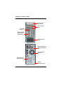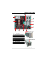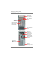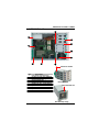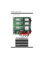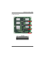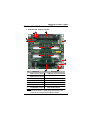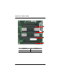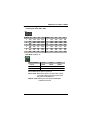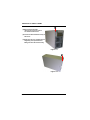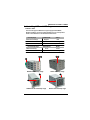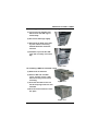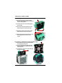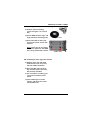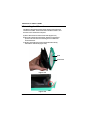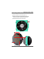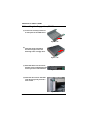
1
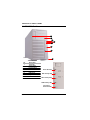
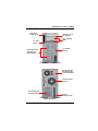
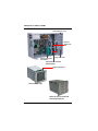
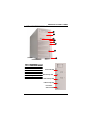
SR209/105/107 USER’S GUIDE
Chenbro
SR209/105/107
Tower&Rackable Server case
USER’S
GUIDE
1
Revision: 1.0
SR209/105/107 USER’S GUIDE
Contents
1.1 Introduction
4
5
1.2 Naming Rule
5
1.3 SR10769 Outline
6
1.4 SR107 Front and Rear views
7
1.5 SR107 Side view
8
1.6 SR20969/10569 Outline
9
1.7 SR209 Front and Rear views
10
1.8 SR209 Side view
11
1.9 SR105 Front and Rear views
12
1.10 SR105 Side view
13
1.11 Front Panel Indicators
14
Chapter 1 SR209/SR105/SR107 Server Case Inside
Chapter 2 Ultra320 SCSI and Serial ATA Backplanes
2.1 Serial ATA Backplane
I.Connectors Layout
II. HDD connectors
III. Jumper Settings
2.2 Ultra320 SCSI Backplane
I.Connectors& Jumpers Layout
II.80 pins SCA Connectors
III.Jumper Settings
Chapter 3 Chassis Installation and Assembly
15
16
16
17
18
19
19
20
21-22
23
3.1 Open the front bezel of SR107
24
3.2 Open the front bezel of SR209/105
24
3.3 Removing the side cover
25
25
25
26
I.SR209 Side Cover
II.SR105 Side Cover
III.SR107 Side Cover
3.4 Installing HDD and HDD cage
I.Before Start
II.Know Hard Disk Carrier
III.Removing Non-Hotswap or Hotswap Cage
Revision: 1.0
27
27
28
29
2
SR209/105/107 USER’S GUIDE
IV. Installing a HDD to hard disk carrier
V. Installing a 80mm fan to Hotswap cage
VI. Installing a 92mm fan to Non-Hotswap cage
VII. Installing HDDs to Non-Hotswap cage
VIII. Installing a drive cage into chassis
3
29
30
30
31
31
3.5 Installing the 120mm fan
32
3.6 Installing a 120mm to chassis
33
3.7 Installing the floppy drive, SR107
34
3.8 Installing the CD-ROM drive
35
3.8 Add-on card guide and Retainer, SR107
36
Revision: 1.0
SR209/105/107 USER’S GUIDE
Chapter 1
SR209/SR105/SR107
Server Case inside
Revision: 1.0
4
SR209/105/107 USER’S GUIDE
1.1 Introduction
This document will guide you for Chenbro server cases- SR107, SR105,
and SR209. They are designed to address the demand of performance
and thermal management, and deliver user friendly mechanical design
as well as configuration flexibilty on data storage.
Additinally, users are able to benefit from their rackable feature. The
SR209 and SR105 can be racked by tray, while the SR107 supports
rackmount solution of slide rails. The specification table below will let
you have general ideas about these server cases.
SR107
SR105
SR209
Model Number
Dimension(mm) 620x220x425
533x198x425
465x198x425
M/B Size(max.)
12” x13”
12” x13”
12”x10.5”
3
3
3
5.25” Bay
3.5” Bay
1
1
0
8
HDD Trays
8
4
Backplane
Ultra 320 SCSI& Serial ATA
Cooling fan
3x120mm
1x120mm, 92mm, 80mm
Front USB
2
2
2
PSU Support
Single PS/2, N+1 Redundant
Single PS/2
Rackmount
by slide rail
by tray
by tray
1.2 Naming Rule
Due to market demand and segement, Chenbro coninutes to develop
the new front bezels for these chassis body. With various front bezel,
the product number will be different. So, to know the naming policy, it
will help you to identify which model your are talking about.
The model number is composed by three parts. They are server case
family code, chassis body, and front bezel serial number. The following
example will explain this rule for you in detail.
Example: SR10769
SR : pedestal server case family code
107: 3 digits, chassis body
69 : 2 digits, front bezel serial number
When you go through this document, the model numbers SR107,
SR105, and SR209 will be used to stand all front bezels not for specific
one.
5
Revision: 1.0
SR209/105/107 USER’S GUIDE
1.3 SR10769 Outline
1
2
3
4
5
6
7
8
No.
1
2
3
4
5
6
7
8
Description
1x3.5”bay
3x5.25” bays
Power button
RESET button
Failure Alarm Mute
USB Cover
KeyLock
Foot Stand
Power ON LED
HDD activity LED
LAN1 activity LED
LAN2 activity LED
Fan Failure
&Overhet LED
Revision: 1.0
6
SR209/105/107 USER’S GUIDE
1.4 SR107 Front and Rear Views
Side Cover
Thumbscrew
Optional 5.25” to
3.5” Bracket
5.25” shielding
Plates
3.5” FDD
Carrier
2 port USB
Bracket
Optional Hotswap
Cage and NonHotswap Cage
SR107 Front View
Changeable PSU
Bracket for PS/2
or N+1 Redundant
Optional 120mm
Rear Fan
Slot bracket with
ventilation holes
Support
Kensington Lock
SR107 Rear View
7
Revision: 1.0
SR209/105/107 USER’S GUIDE
1.5 SR107 Side View
Detachable top cover
Optional
120mm T25
fans
Add-on card guide
and retainer
3 pairs slide rails
Optional SCSI and Serial
ATA blackplane
Optional 92mm fan
Non-Hotswap Cage
Hotswap Cage for SCSI and
Serial ATA backplane
Revision: 1.0
8
SR209/105/107 USER’S GUIDE
1.6 SR10569/SR20969 Outline
1
2
3
4
5
6
7
8
No.
1
2
3
4
5
6
7
8
Description
5.25” to 3.5” bracket
3x5.25” bays
USB Cover
Power ON LED
Power button
RESET button
Alarm Mute
HDD activity LED
KeyLock
Foot Stand
LAN1 activity LED
LAN2 activity LED
Fan Failure
&Overhet LED
9
Revision: 1.0
SR209/105/107 USER’S GUIDE
1.7 SR209 Front& Rear Views
Optional 5.25” to
3.5” Bracket
5.25” shielding
Plates
2 port USB
Bracket
Optional Hotswap
Cage and NonHotswap Cage
Front ventilation
holes
SR209 Front View
Optional Single PS/2
ATX12V and EPS12V
PSU
Optional 120mm
Rear Fan
Slot bracket with
ventilation holes
Support
Kensington Lock
SR209 Rear View
Revision: 1.0
10
SR209/105/107 USER’S GUIDE
1.8 SR209 Side Views
11
10
1
9
2
3
4
8
7
6
5
80mm fan holder
No.
1
2
3
4
5
6
7
8
9
10
11
Description
Easy bezel removal design
Screws for slide rail installation
HDD Cage
Optional 92mm fan
Add-on card retainer
80mm fan holder
Support M/B up to 12”x10.5”
Optional screwless holder
Optional 120mm rear fan
Side cover latch
6 pcs 5.25” slide rails
Hotswap Cage
optional 92mm fan
Non-Hotswap Cage
11
Revision: 1.0
SR209/105/107 USER’S GUIDE
1.9 SR105 Front& Rear Views
Optional 5.25”
to 3.5” Bracket
5.25” shielding
Plates
2 port USB
Bracket
Optional Hotswap
Cage and NonHotswap Cage
Front ventilation
holes
SR105 Front View
Side cover
thumbscrews
Optional Single
PS/2 or MiniRedundant PSU
Optional 120mm
Rear Fan
Slot bracket
with ventilation
holes
Support
Kensington Lock
SR105 Rear View
Revision: 1.0
12
SR209/105/107 USER’S GUIDE
1.10 SR105 Side View
10
9
1
2
8
3
4
7
6
5
80mm fan holder
No.
1
2
3
4
5
6
7
8
9
10
Description
Easy bezel removal design
Screws for slide rail installation
Non-Hotswap HDD Cage
Optional 92mm fan
Add-on card retainer
Support 12” x13” server board
Optional screwless holder
Optional 120mm rear fan
Optional PS/2 or Mini-Redundant
6 pcs 5.25” slide rails
Hotswap Cage
optional 92mm fan
Non-Hotswap Cage
13
Revision: 1.0
SR209/105/107 USER’S GUIDE
1.11 Front Panel Indicators
No.
LED
1 Power
2 HDD Activity
3 LAN1 Activity
4 LAN2 Activity
5 Overheat& Fan failure
Status of LED colors
Green, Power on
Orange, Access IDE HDD
Green/Cable connection
Blinking green/LAN Activity
Red, Fan Failure or HDD overheat
No.
LEDs
1 Power
2 HDD Activity
3 LAN1 Activity
4 LAN2 Activity
5 Overheat& Fan failure
Color of Wires
Green/Black
RED/Black
Orange/Black
Yellow/Black
Purple/Black, connect to backplane
Revision: 1.0
14
SR209/105/107 USER’S GUIDE
Chapter 2
Ultra320 SCSI and Serial
ATA backplanes
15
Revision: 1.0
SR209/105/107 USER’S GUIDE
2.1 Serial ATA Backplane
I. Connectors Layout
1
2
10
9
No.
1
2
3
4
5
6
7
8
9
10
Revision: 1.0
8
3
5
7
6
4
Description
J9, 4pin DC Power Connector
J10, 4pin DC Power Connector
FAN1, 3P3C Fan Connector
FAN2, 3P3C Fan Connector
J5, 7P serial ATA Connector
J7, 7P serial ATA Connector
J6, 7P serial ATA Connector
J8, 7P serial ATA Connector
S1, Hardware Monitor switch
JP1, Front Panel Control Jumper
16
SR209/105/107 USER’S GUIDE
II. HDD Connnectors
1
2
3
4
No.
1
2
3
4
17
Description
J1, serial ATA HDD1 connector
J2, serial ATA HDD2 connector
J3, serial ATA HDD3 connector
J4, serial ATA HDD4 connector
Revision: 1.0
SR209/105/107 USER’S GUIDE
III. Jumper Settings
S1, Hardware Monitor Switch
ON
Position No.
Function
ON
OFF
1
FAN1 monitor
*Disable
Enable
2
FAN2 monitor
*Disable
Enable
3
Alarm Temperature
50℃
*60℃
1 2 3
JP1, Front Panel Control Jumper
6
Pin No.
Function
Pin No.
Function
1
System Failure LED+
2
System Failure LED-
3
GND
4
Alarm Mute Switch+
5
N/A
6
Alarm Mute Switch-
1
Note: * Default Settings
Revision: 1.0
18
SR209/105/107 USER’S GUIDE
2.2 Ultra320 SCSI Backplane, VER:1
I. Connectors& Jumpers Layout
8
10
9
7
1
6
11
12
14
13
2
3
5
No.
Description
No.
4
Description
1
JPWR1,4-pin DC Power 8
TEMP_SET, Alarm Temperature
2
JPWR2,4-pin DC Power 9
J3, Front Panel Control
3
FAN1, 3P3C Connector 10
Terminator connector
4
FAN2, 3P3C Connector 11
SW1, HDD1 ID Swich
5
68-pin SCSI Connector 12
SW2, HDD2 ID Switch
6
FAN_DIS, FAN Monitor
13
SW3, HDD3 ID Switch
7
J2, HDD Motor Control
14
SW4, HDD4 ID Switch
NOTE:
This version doesn’ t support daisy chain feature, so the
connector 10 is used for external SCSI terminator.
19
Revision: 1.0
SR209/105/107 USER’S GUIDE
II. 80 pins SCA Connectors
1
2
3
4
No.
Description
No.
Description
1
80-pin SCA Connector 1
3 80-pin SCA Connector 3
2
80-pin SCA Connector 2
4 80-pin SCA Connector 4
Revision: 1.0
20
SR209/105/107 USER’S GUIDE
III. Jumper Settings
SCSI ID (SW1, SW2, SW3, SW4)
ON
1 2 3 4
SCSI ID P1
0
1
2
3
4
5
6
7
OFF
ON
OFF
ON
OFF
ON
OFF
ON
P2
P3
P4
OFF
OFF
ON
ON
OFF
OFF
OFF
OFF
OFF
OFF
OFF
OFF
OFF
OFF
ON
ON
ON
ON
ON
ON
OFF
OFF
OFF
OFF
SCSI ID
8
9
10
11
12
13
14
15
P1
P2
P3
OFF
ON
OFF
ON
OFF
ON
OFF
ON
OFF
OFF
ON
ON
OFF
OFF
ON
ON
OFF
OFF
OFF
OFF
ON
ON
ON
ON
P4
ON
ON
ON
ON
ON
ON
ON
ON
HDD Motor Control, J2
1
6
Operation Mode
P1-P2
P3-P4
P5-P6
Normal
OPEN
OPEN
SHORT
*DELAY START
SHORT
OPEN
OPEN
REMOTE START
OPEN
SHORT
OPEN
Normal: Motor spins up at D.C. power on.
DELAY START: Motor spins up at D.C. power on after a delay
in seconds 12 times the value of the numeric
SEL_ID for the SCSI devices.
REMOTE START: Motor spins up only when START UNIT
command is received.
21
Revision: 1.0
SR209/105/107 USER’S GUIDE
Alarm Temperature, TEMP_SET
1
6
Temperature
P1-P2
SHORT
P3-P4
P5-P6
OPEN
OPEN
* 55℃
OPEN
SHORT
OPEN
65℃
OPEN
OPEN
SHORT
45℃
Note: * Default Settings
FAN Monitor function, FAN_DIS
1
6
Monitor Mode
FAN1(P1-P2)
FAN2(P3-P4)
*DISABLE
SHORT
SHORT
ENABLE
OPEN
OPEN
Front Panel Control,J3
1
6
Pin No.
1
Description
Alarm LED+
3
N/A
4
N/A
5
MUTE SWITCH
6
MUTE SWITCH
Revision: 1.0
Pin No.
2
Description
Alarm LED-
22
SR209/105/107 USER’S GUIDE
Chapter 3
Chassis Installation and
Assembly
23
Revision: 1.0
SR209/105/107 USER’S GUIDE
3.1 Open the front bezel of SR107
A keylock secures the front bezel to protect your system against
unauthorized access:
(a). Insert the key into the security lock, and turn it clockwise until it
points to the unlock icon as figure 3-1.
(b).Press two release button on top of front bezel, and the pull it toward
yourself (Figure 3-2).
(c).Take off the front bezel from chassis body.
Figure 3-1
Figure 3-2
3.2 Open the front bezel of SR209/105
1
(a).Unlock the keylock on rear panel
if necessary
(b).Remove the side cover as
instrucions decribed in next
section
(c).Swing the release lever(1)
anticlockwise,and then take off
it from chassis.
Figure 3-3
Revision: 1.0
1
24
SR209/105/107 USER’S GUIDE
3.3 Removing the side cover
I. SR209 Side Cover
(a).Unlock the keylock(1) on rear
1
panel.
(b).Push side cover latch(2) at upper
2
position.
(c).Slide the side cover backward,
then upward before taking it off
from the chassis body.
Figure 3-4
Figure 3-5
1
II. SR105 Side Cover
(a). Loosen the two thumbscrews(1) at
end of side cover on rear panel.
(b). Slide the side cover backward, then
upward before taking it off from the
chassis body.
1
Figure 3-6
25
Revision: 1.0
SR209/105/107 USER’S GUIDE
III. SR107 Side Cover
1
(a).Remove the front bezel.
Refer to the previous section
for detailed instructions.
(b).Loosen the three thumbscrews(1) of
side cover.
(c).Slide the side cover toward until it is
stopped(2), then upward before
taking it off from the chassis body.
Figure 3-7
2
Figure 3-8
Revision: 1.0
26
SR209/105/107 USER’S GUIDE
3.4 Installing HDD and HDD Cage
I. Before start
There are two types of HDD drive cages equipped with SR209,
SR105, and SR107, and exist a little bit differences for each product
model. These differences are detailed as table below.
Hotswap Cage
SR209/SR105
SR107
80mm Fan Holder(1)
Support
N/A
Location of thumbscrews(2)
Up&down
Left& Right
Type of thumbscrews(3)
#6-32*D12
#6-32*D8
Non-hotswap Cage
SR209/SR105
SR107
Front
Front
Up&down
Left& Right
92mm front fan(4)
Location of thumbscrews(5)
2 3
2 3
1
SR209/105 Hotswap Cage
SR107 Hotswap Cage
4
5
SR209/105 Non-Hotswap Cage
27
4
5
SR107 Non-Hotswap Cage
Revision: 1.0
SR209/105/107 USER’S GUIDE
II. Know hard disk carrier
The hard disk carrier is used to hotswap cages of SR209, SR105,
and SR107. The assembly parts are detailed as below picture.
7
1
6
2
3
5
4
No.
1
2
3
4
5
6
7
Description
Contact spring to chassis
HDD Power ON LED
HDD activity LED
Release button
Contact spring to upper carrier
Lever
Air dam
NOTE:
User could not fully install four HDDs to the
hotswap cage. Under this situtation, the
fresh air won’t flow over these installed
hard drives, and cause bad cooling on them.
The air dam is used to force fresh air going
through them. Surely, if you want to install a
HDD to a carrier, you have to remvoe air dam
first.
Revision: 1.0
28
SR209/105/107 USER’S GUIDE
III. Removing Hotswap or Non-Hotswap Cage
(a).Loosen the four thumbscrews,
which secure the HDD cage to
chassis body.
(b).Pull out the HDD cage slightly.
(c).Disconnect the SCSI, serial ATA,
or power cables. If necessary,
the SCSI terminator should be
removed.
Figure 3-9
(d).Continute to pull out this HDD
cage until it is totally out of drive
bay.
Figure 3-10
IV. Installing a HDD to hard disk carrier
(a).Remove the air dam first.
(b).Install a HDD into hard disk
carrier, and then secure it with
the four screws you can find in
screw bag.
(c).Insert the hard disk carrier into
Figure 3-11
the Hot-swap cage with lever still
extended.
(d).Push the lever back until it clicks
into place.
Figure 3-11
29
Revision: 1.0
SR209/105/107 USER’S GUIDE
V. Installing a 80mm fan to Hotswap cage
1
(a). Insert a 80/T25mm fan into fan holder.
Please check if the direction of air flow is
correct as Fingurexxx.
(b).Let these fan wires be holded by gap(1)
of fan holder.
(c). Press the ears(2) to let them can hook
the mouting holes of Hotswap cage.
2
(d).Align the position pins(3) of fan holder
with four key holes(4) on backplane.
4
3
Figure 3-12
(e). Push toward to let the position pins into
holes totally until you hear a crack
sound.
Figure 3-13
VI. Installing a 92mm fan to Non-Hotswap cage
(a). Insert plastic holder clip(1) to both sides
of cooling fan end-by-end.
1
(b).Insert the 92mm fan into Non-Hotswap
cage or to slide rail of SR209/105 front
fan as Figurexx.
(c). To remove it, you can press both ears(2),
and then pull it out.
2
Figure 3-14
Figure 3-16
Revision: 1.0
Figure 3-15
30
SR209/105/107 USER’S GUIDE
VII. Installing HDDs to Non-Hotswap Cage
(a).Find the special mounting
screws as Figure 3-17 in screw
bag.
(b).Put the HDD into drive cage, and
align with those mounting holes.
Figure 3-17
(c).Secure this HDD to drive cage
via the four specifc screws with
washers.
Note: Please have to use washer
with screw. Otherwise, that HDD
won’t be grounded with chassis.
Figure 3-18
VIII. Installing a drive cage into chassis
(a).Hold the drive cage with both
hands because it is very heavy
with four HDDs instalaltion.
(b).Insert the HDD cage into drive
bay, and then push it into more,
but still keep extended.
(c).For convenience of cabling, you
can connect all cables at this
status.
(d).Let the HDD cage to contact
chassis, and the secure it with
four thumbscrews
31
Revision: 1.0
SR209/105/107 USER’S GUIDE
3.5 Installing the 120mm fan
The SR107 is designed to support three 120mm cooling fans with
screwless fan holder. There are two fans in middle of chassis, and
the other one is mounted on rear panel.
(a). Put a 120mm fan into hooks of fan holder (Figure 3-19)
(b).Press this 120mm fan to fan holder, and the four positioned
pins have to insert into four mounting holes of 120mm fan
around the frame.
(c). Please check if the four hooks of fan holder have exactly
fastened this 120mm fan (Figure 3-20).
Hook
Position Pin
Figure 3-19
Figure 3-20
Revision: 1.0
32
SR209/105/107 USER’S GUIDE
3.6 Installing a 120mm fan to chassis
(a).Install the 120mm fan to fan holder (Figure 3-21).
(b).Put the four hooks(1) into specified 120mm fan mouting
holes(2) at rear panel or middle panels (Figure 3-23).
(c).Slide it toward until you hear a crack sound.
1
Figure 3-21
2
2
Figure 3-23
33
2
Figure 3-22
Revision: 1.0
SR209/105/107 USER’S GUIDE
3.7 Installing the floppy drive, SR107
(a). Loosen two screws(1) fastened
on side panel of the FDD carrier.
1
Figure 3-24
(b).Insert the hooks, pointed by
arrowed in Figure 3-25, into
mounting holes of floppy drive.
Figure 3-25
(c). Push FDD down into the carrier,
and then secure FDD with the two
screws you have removed earier.
Figure 3-26
(d).Insert the drive carrier with FDD
in the drive bay until you hear a
crack sound.
Figure 3-27
Revision: 1.0
34
SR209/105/107 USER’S GUIDE
3.8 Installing the CD-ROM drive
(a).Take out a pair of slide rails from
holder(SR209/SR105) or remove
them from side panel of drive
cage frame in SR107.
Figure 3-28
(b).Insert both guide pins, circled in
Figurexxx, of slide rail in
moutning holes of CD-ROM Drive,
and then secure them with
screws side by side.
(c).Insert the CD-ROM drive in the
drive bay until you hear a crack
sound.
Figure 3-29
Figure 3-30
35
Revision: 1.0
SR209/105/107 USER’S GUIDE
3.9 Add-on card guide and Retainer, SR107
I. Detaching Add-on card retainer
(a). For convenience of instalaltion or
cabling, user could want to remove
the add-on card retainer.
(b).Push the release button on the top of
add-on card holder, and then pull it
out.
(c). Move it upward slightly, and then
detach it totally from chassis body.
Figure 3-31
II. Releasing Add-on card retainer
(a). Press both releasers, pointed by
arrows, and rotate toward righ t.
Figure 3-32
(b).The hold down clamp will be fixed at
position as Figure 3-33.
User can install the full-size PCI card,
which will be guided and fastened by
this holder.
Figure 3-33
Revision: 1.0
36