1
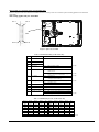
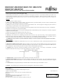
MBA3300NC, MBA3300NP, MBA3147NC, MBA3147NP,
MBA3073NC, MBA3073NP
HARD DISK DRIVES INSTALLATION GUIDE
CARE OF YOUR FUJITSU HARD DISK DRIVE (HDD)
Careful handling and installation of your HDD is paramount to the longevity of the unit. The internal mechanism of the HDD can be
seriously damaged if the HDD is subjected to forces outside the environmental specifications. When transporting the HDD, always use the
original packaging in which the HDD was delivered to you, and avoid exposing the HDD to extreme changes in temperature to minimize the
risk of condensation.
Handling
1. Never drop the unit. Handle it with care.
2. Never move the HDD while the disks are spinning. Note that the disks spin when the HDD is powered on and also immediately after
power off. Refer to the Start/Stop specification for your HDD.
3. Always turn off the power before connecting or disconnecting the interface cable. The same applies to changing any of the switches or
terminal settings except Write protect switch on NP model drives.
4. Never place the HDD in the vicinity of equipment giving off strong magnetic fields, such as CRT monitors, televisions, or loudspeakers.
5. Never use any cleaning agents or liquids on the HDD.
6. Always use an antistatic mat and wrist strap when handling the HDD. Hold the HDD by the base casting and never touch the components
on printed circuit board assembly.
7. Never remove any labels from the HDD or deface them in any way.
8. Never open the HDD for any reason. Doing so will void any warranties.
9. Always pay close attention to the mounting specifications such as those for sway space and cooling. If the temperature difference
between the storage location and installation locations exceeds 10°C, for temperature acclimation purposes, leave the HDD in the new
location for at least two hours before turning it on. This minimizes any risk of condensation forming on the HDD.
The HDD needs NO preventative or periodic maintenance during its service life if properly used in the appropriate environment.
INSTALLATION
1. ORIENTATION–The HDD can be installed flat on any of its six sides. Inclination from vertical or horizontal plane should not exceed
5°.
2. MOUNTING SCREW INSTALLATION–When the mounting screw holes on the side of the HDD are used, be sure to use the two pairs
of outer holes. Do not use the center hole in conjunction with only one of the outer holes. The screws must not penetrate the HDD by more
than 5.0 millimeters. Impact caused by the electric screwdriver must be within the HDD specifications.
3. COOLING–Allow space above and below the HDD to provide an adequate air flow. Fan cooling is recommended. The HDD
temperature measured at center of top cover (label side) should never exceed 60°C. See Table 1.
Table 1. Reference value of airflow
Environmental temperature
Required velocity of airflow
30°C
> 0.3m/s
35°C
> 0.6 m/s
40°C
> 0.9 m/s
45°C
> 1.5 m/s
4. TERMINATION–A terminator should be installed externally at both ends of the SCSI bus.
5. TERMINATOR POWER–Terminator power must be supplied to terminator for correct operation. This can be supplied from either the
HDD, except for NC model or the SCSI bus. If only NC models are connected to the SCCI bus, terminator power should be supplied
externally.
6. CONNECTING–To avoid potential damage to the HDD, make sure that connector type and orientation is correct.
CAUTION: Your warranty may be voided if the connector is damaged as a result of incorrect insertion.
FUJITSU LIMITED
Storage Products Group
4-1-1 Kamikodanaka, Nakahara-ku, Kawasaki 211-8588, Kanagawa-ken, Japan
Copyright © 2007 FUJITSU LIMITED
Undermentioned information is effective only in EU for traceability of the EMC Directive
Manufacturer:
Fujitsu Limited
4-1-1 Kamikodanaka, Nakahara-ku, Kawasaki 211-8588, Kanagawa-ken, Japan
Authorized representative importer / distributor in EU:
Fujitsu Europe Limited
Hayes Park Central, Hayes End Road, Hayes, Middlesex, UB4 8FE, United Kingdom
http://www.fujitsu.com/
C141-E271-01EN
Diagram and user-selectable options (on NP models only)
Below is a diagram of the main board of SCSI HDD and also a summary of the user-selectable options including guidelines for installation
of the HDD.
This setting applies only for NP models.
Pin 1
Pin 2
CN2
Pin 23
Pin 24
Figure 1. Option select terminal
Table 2. CN2 Terminal Setting (on NP models only)
Setting Item
Pin #
1-2
SCSI ID 0
3-4
SCSI ID 1
5-6
SCSI ID 2
7-8
SCSI ID 3
9-10
Write protect
Function
See Table 3.
Open ……Write operation is enabled.
(default)
Short ……Write operation is disabled.
11-12
Open ……Starting of motor is controlled with START/STOP
UNIT command.
Motor start mode
13-14
Force Narrow
Short ……Motor is started immediately after power supply is
turned on or microcode is downloaded.
(default)
Open ……16-bit bus mode
(default)
Short ……Pull upper 8bits and parity internally when HDD is
connected to Narrow SCSI bus.
15-16
Open ……Follows DIFFSNS signal level on SCSI bus.
Force Single Ended
(default)
Short ……Single-Ended mode
17
GND
18, 19
N.C
20
IDD Reset
Input signal
21-22
Remote LED
Output signal
23-24
Terminal power supply
Open ……HDD does not supply terminator power to SCSI bus.
Short ……HDD supplies terminator power to SCSI bus.
(default)
Table 3. SCSI ID Setting on CN2 (on NP models only)
Pin 1-2
Pin 3-4
Pin 5-6
Pin 7-8
ID
Pin 1-2
Pin 3-4
Pin 5-6
Pin 7-8
Open
Open
Open
Open
0
Open
Open
Open
Short
ID
8
Short
Open
Open
Open
1
Short
Open
Open
Short
9
Open
Short
Open
Open
2
Open
Short
Open
Short
10
Short
Short
Open
Open
3
Short
Short
Open
Short
11
Open
Open
Short
Open
4
Open
Open
Short
Short
12
Short
Open
Short
Open
5
Short
Open
Short
Short
13
Open
Short
Short
Open
6
Open
Short
Short
Short
14
Short
Short
Short
Open
7
Short
Short
Short
Short
15
(default)