1
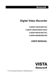
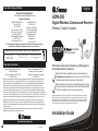
English
Help Desk / Support Details
Swann Technical Support
ADW-300
All Countries E-mail: [email protected]
Telephone Helpdesk
UNITED STATES toll free
1-800-627-2799
1-877-274-3695
(Su, 2pm-10pm US PT)
(M-Th, 6am-10pm US PT)
(F 6am-2pm US PT)
USA Exchange & Repairs
562-777-2551
(M-F, 9am-5pm US PT)
AUSTRALIA toll free
1300 138 324
(M 9am-5pm AUS ET)
(Tu-F 1am-5pm AUS ET)
(Sa 1am-9am AUS ET)
New Zealand toll free
0800 479 266
International
+61 3 8412 4610
See http://www.worldtimeserver.com for information on different time zones
and the time in Melbourne Australia compare to your local time.
WARNING: IMPORTANT NOTICE ABOUT CORRECT USE OF POWER ADAPTER
The correct orientation
for the enclosed power
adapter is in a vertical
or floor mount position.
L’orientation correcte pour L’adapteur
secteur fourni est dans une position
verticale ou plancher-monte.
La orientacion correcta para el
adaptador electrico incluido es en
posicion vertical o instalado en el
suelo.
Warranty Information
Swann Communications U.S.A. Inc.
12636 Clark Street
Santa Fe Springs, CA 90670 USA
1-800-627-2799
Swann Communications PTY. LTD.
Building 4, 650 Church Street,
Richmond, Victoria 3121 Australia
1300 138 324
Swann Communications warrants this product against defects in workmanship and material for a
period of one (1) year from it’s original purchase date. You must present your receipt as proof of
date of purchase for warranty validation. Any unit which proves defective during the stated period
will be repaired without charge for parts or labour or replaced at the sole discretion of Swann.
The repair or replacement will be warranted for either ninety days or the remainder of the original
one year warranty period, whichever is longer. The end user is responsible for all freight charges
incurred to send the product to Swann’s repair centres. The end user is responsible for all shipping
costs incurred when shipping from and to any country other than the country of origin. The warranty
does not cover any incidental, accidental or consequential damages arising from the use of or the
inability to use this product. Any costs associated with the fitting or removal of this product by a
tradesman or other person or any other costs associated with its use are the responsibility of the
end user. This warranty applies to the original purchaser of the product only and is not transferrable
to any third party.
Unauthorised end user or third party modifications to any component or evidence of misuse or
abuse of the device will render all warranties void.
www.swannsecurity.com
12
EN15102008
Digital Wireless Camera and Receiver
Wireless Outdoor Camera
STOP
Help Desk
Has the answers
If this device does not work when you first plug it in,
do not take it back to the store.
Contact the Swann Helpdesk using our fast e-mail servic
[email protected] or call us on one of the Toll-Free
numbers shown on the back cover of this booklet.
Most problems can be quickly and easily fixed with a simple
e-mail or a quick chat with one of our friendly technical staff.
(Toll-Free available in the US and Australia only)
Note: Wireless Networks (WiFi) may interfere with and/or experience interference caused by
the transmitter in this unit. Changing the receiver to another channel/frequency or setting the
Wireless Network (i.e. Wireless Access Point) to a frequency further away from the camera’s
set frequency can alleviate this problem. Consult the documentation of your Wireless LAN
device for information on how to change the transmission frequency.
Installation Guide
Index
Introduction
Package Contents
Important Safety Instructions
Camera & Receiver Layout
Installation
Receiver Setup
Pairing Cameras
Troubleshooting, Hints & Tips
Troubleshooting
Technical Specifications
Help Desk / Support Details
Warranty Information
Troubleshooting (cont)
2
2
3
4
4-5
6-8
9
10
11
11
Back Cover
Back Cover
Introduction
Thank you for purchasing the ADW-300 Digital Wireless Camera Kit by Swann.
The ADW-300 represents a leap forward in Wireless Security with improved reception
and reliable transmission of digital signals. Please read this user manual carefully before
installing or using these units.
Important Safety Precautions: Please read before installing and using this product.
Damages caused by non-compliance with this operating manual will void the warranty.
We will not assume any liability for damages to items or persons caused by improper
handling or non-compliance with the safety notices. Any warranty claim will be null
and void in such cases.
Package Contents
• 1 x Wireless Receiver
• 1 x Wireless Camera
• 1 x Camera Stand
• 1 x Power Adapter for Camera
• 1 x Power Adapter for Receiver
• 1 x A/V Cable
• 2 x Antennas - for Camera and Receiver
• Quick Start Guide
If any of these items are missing, please contact your Swann for assistance.
NOTE:
All jurisdictions have specific laws and regulations relating to the use of cameras. Before
using any camera for any purpose, it is the buyer’s responsibility to be aware of all applicable laws and regulations that prohibit or limit the use of cameras and to comply with the
applicable laws and regulations.
The legality of watching people other than yourself changes from country to country and
even state to state. Contact your local government’s privacy information body or your local
Police for more information on what if any restrictions you may face.
2
This section offers some helpful information to overcome most of the problems you may encounter.
About 2.4GHz Digital Wireless Signal: This innovative digital wireless solution integrates advance Frequency Hopping
Spread Spectrum (FHSS) technology. This technology greatly reduces the interference that comes from other devices
using the same radio frequency (2.4GHz), e.g. WIFI, Bluetooth, Zigbee, cordless phone etc. You now can enjoy a more
pleasant wireless surveillance quality without flicking and noisy image. However , weaker signal (lag or still image) can
be observed yet from time to time, depending on the environment where the system is installed. Complied with FCC
part 15.247, ETSI (EN) 300 328, audio / video signals transmitted out about or over 500 ft / 150 m in line of sight should
be supported. Line of sight installation, though, is usually not a common practice. Factors affecting transmission include
microwave ovens or other high frequency electromagnetic waves. Reinforced concrete walls, large scale metal products
and metal furniture should not be located near the camera or the receiver. Obstacles as a person passing through may
cause an unstable signal.
How do I improve the wireless signal quality? If possible, remove obstacles in between camera and receiver that
might deflect the signal. These could include furniture, cabinets, and walls. If you feel the wireless signal is not good
enough, place the receiver at a new angle or readjust its position to make an improvement. Or simply relocate the camera closer to the receiver.
How to improve the image quality? On QVGA size (X2, zoom IN), pixel scattering is unavoidable. However, you can
try to zoom out the image to VGA size. By doing so, more pixels can be scattered on the monitor o have the best display
performance, 32 inch or smaller monitor / TV is suggested.
Technical Specifications
Image
Image Sensor
Video Quality
No. of Effective Pixels
Minimum Illumination
Day/Night Mode
Lens
Viewing Angle
1/4” CMOS Sensor
380 TV Lines
640 x 480 (VGA) / 320 x 240 (QVGA)
2 Lux Color, 0 Lux B&W
Automatic
F3.6mm
H:53°,V:40°
Night Vision
Number of Infra-Red LEDs
Infra-Red Wavelength
Night Vision Distance
24
850nm
25’ (8m)
General
Power Supply
Operating Temperature
Dimensions - Camera
Weight
PC Out
TV Out
DC 5V
14°F to 122°F, 10°C +50°C
6.3” x 2.5” x 6.3”, 160x63x161mm
0.7lbs, 320g
USB Compatible
3.5mm jack to RCA
Wireless
Reception Range
Frequency Transmission Channels
Receiver Power Supply
Camera Support
165’, 50m
2.4GHz
Frequency Hopping GFSK
DC 5V
Up to 4 (ADW-300)
11
Troubleshooting, Hints & Tips
Important Safety Precautions
Before requesting service, please make the below checks. If you are in doubt about some of
the check points, or if the remedies indicated in the chart do not solve the problem, please
contact us.
Problem
Possible Causes
Remedies
System message
shows ”NO
Connection”
No power supply to
corresponding camera(s)
First identify the channel number, find
find the corresponding camera. If camera
power status indicator (RED LED) is off,
check power adapter and power cable
connection.
Channel is not paired with
camera yet
First identify camera has no image, draw
the camera near the receiver then pair
the camera to desired channel. See page
11 for detail. Once pairing completed
and camera is picked up by the receiver,
camera status indicator (GREEN LED)
will light up.
Service out of range
Draw the camera near the receiver
Signal been blocked
If possible, remove major obstacles
between the camera and the receiver. Or
relocate the camera to proper location.
Camera antenna
connection loss
Secure camera antenna to camera body
tightly.
Antenna directional
limitation
Adjust camera antenna and receiver
position.
Signal being blocked
If possible, remove major obstacles
between camera and receiver. Or relocate
the camera to proper location.
Strong radio signal near
by
Keep WIFI router away from the camera
and/or receiver.
Strong electromagnetic
interference nearby
Keep working motors (hair dryer/heat fan/
air conditioner/water pump) or microwave
oven away from the camera and/or
receiver.
Channel(s)
disappear during
auto or manual
scan
Scan channel(s) been set
OFF
Go to menu; enable the channel(s). See
page 10 for detail.
Dim/over-bright
image at night
time
Low light vision distance
too short/too far
Ideal low light vision distance is from 9 ft
/ 3m to 24 ft / 8 m. Adjust the camera to
have camera view fit in this distance.
Low signal or
unstable signal
10
Please read before installing and using this Product. Damage caused by non-compliance with this operating
manual will void the warranty. We will not assume any liability for damages to items or persons caused by
improper handling or non-compliance with the safety notices. Any warranty claim will be null and void in such
cases.
1. Do not drop, puncture or disassemble the camera or receiver; otherwise the warranty will be voided.
2. Keep adapters away from moisture.
3. Never tug on the power cords. Use the plug to unplug it from the wall outlet.
4. Do not expose the camera or receiver to extreme high temperatures or aim the lens in direct sunlight. Doing
so may damage the camera.
5. Use the devices with care. Avoid pressing hard on the camera or receiver body.
6. For your own safety, avoid using the camera or power off the camera when there is a storm or lightning.
7. Remove the power adapter during long periods between usages.
8. Use only the accessories and power adapters supplied by the manufacturer.
9. To meet the regulations pertaining to parental responsibility, keep the devices out of the reach of infants.
10. Check power cables do not get crushed or damaged by sharp edges whenever the devices are in operation.
FCC Compliance Statement:
This device complies with Part 15 of the
FCC Rules. Operation is subjected to the
following two conditions:
(1) this device may not cause harmful
interference, and
(2) this device must accept any
interference received, including
interference that may cause
undesired operation.
Products with CE Marking comply with
EMC Directive (2004/108/EC); Low Voltage
Directive (73/23/EEC); R&TTE(1999/5/EC)
issued by the Commission of the European
Community. Compliance with these
directives implies conformity to the following
European Norms:
EMC: EN 301 489
LVD: EN 60950
Radio: EN 300 328
FCC/CE WARNING
This equipment has been tested and found to comply with limits for a Class B digital device, pursuant to Part 15
of the FCC rules and ETSI (EN) 300 328. These limits are designed to provide reasonable protection against
harmful interference in residential installations. This equipment generates, uses, and can radiate radio frequency
energy, and if not installed and used in accordance with the instructions, may cause harmful interference to radio
communications.
However, there is no guarantee that interference will not occur in a particular installation. If this equipment does
cause interference to radio or television equipment reception, which can be determined by turning the equipment
off and on, the user is encouraged to try to correct the interference by one or more of the following measures:
- Reorient or relocate the receiving antenna.
- Move the equipment away from the receiver.
- Plug the equipment into an outlet on a circuit different from that to which the receiver is connected.
- Consult the dealer or an experienced radio/television technician for additional suggestions.
You are cautioned that any change or modifications to the equipment not expressly approved by the party
responsible for compliance could void Your authority to operate such equipment.
Disposal
If the camera system no longer functions or can no longer be repaired, it must be disposed of according to the
valid statutory regulations. Disposal of spent batteries / accumulators:
You are required by law (Battery Ordinance) to return all spent batteries and accumulators.
Disposing of spent batteries/accumulators with common household waste is prohibited!
Batteries/accumulators that contain hazardous substances are marked with the symbols
on the side. These symbols indicate that it is prohibited to dispose of these batteries/
accumulators in the household waste.
The abbreviations for the respective heavy metals are: Cd= cadmium, Hg= mercury, Pb=
lead. You can return spent batteries and accumulators that can no longer be charged to the
designated collection points in your community, outlets or wherever batteries or accumulators
are sold. Following these instructions will allow you to fulfil the legal requirements and
contribute to the protection of our environment!
3
Camera & Receiver Layout
Pairing Cameras
Back side
13
10
11
12
11
8
9
M
3
4
7 6
5
Pairing Camera(s)
This function is available for multi-camera users
It is highly recommended to pair the camera before
hardware installation.
Before pairing the camera, make sure camera is power
ON, camera status indicators shown:
A. Simply pair the camera by selecting the desired channel in the
OSD menu.
B. Only assign one camera to one channel. Channel memory will be
overwritten if the next camera is assigned to the same channel.
C. Pairing new camera to channel 3, settings as shown:
Receiver
1. Receiver antenna
2. USB port
3. A/V out
4. DC Power
5. Signal LED
6. Pairing LED
7. Power LED
8. Power supply
9. Mini jack to RCA
cable
1
2
Camera Parts
1. Camera Lens
2. IR LED
3. Antenna
4. Power Jack
5. Camera Stand
6. 1 CDS
7. Microphone
8. Cam Pair
9. Power adaptor
10.Power LED
11.U holder / U holder
screw
12. T- bolt
13. Sunshield
8
(Pair).
D. Press
E. System will count down within 60 seconds, system message as
shown:
60
9
F. Within 10 seconds, press the Pair Key on
the back of camera.
Installation
Pairing key
Step1: Hardware Set Up
3
G. Once pairing completed, camera and
receiver status indicators appear as
shown
Camera Assembly / Adjustment
A. Loosen U holder screws; slide the sunshield to ideal position.
B. U bracket can be installed on camera top side for ceiling mount.
C. Secure U holder with screws when done.
D. Adjust camera for proper view angle. Secure the stand with T-bolt when done.
4
Reset
A. Select the item “Reset” in the menu.
.
B. Press
C. The original default settings of the system will be restored.
Reset
9
Receiver Setup (cont)
Installation (cont)
Step4: Advance Operation
Audio Vol
Scan Time
Camera 1
Camera 2
Camera 3
Camera 4
Pair CAM
Reset
10
OFF
ON
ON
ON
ON
1234
Audio Vol
Using the Menu
You can Use
(Left / Right / Up /
Down) to select and change the settings.
By Pressing M (Menu), you can enter / exit OSD
menu
Setting Audio Volume
You can Use
(Left / Right) to
change Audio Volume from 0 to 20.
Setting Auto / Manual Scan
This function is available for multi-camera user
Scan Time will be turned off every time after you press
Scan Time
Camera 1
Camera 2
Camera 3
Camera 4
OFF
ON
ON
ON
ON
Scan Time
Camera 1
Camera 2
Camera 3
Camera 4
5 Sec
ON
ON
ON
ON
(Cam) for manual scan
A. Use
(Left / Right) to change Scan
Time interval between OFF / 5 sec / 10 sec / 15sec.
B. Default setting is OFF, system will not scan and camera display
has to be manually assigned.
Skip Certain Camera(s) During Scan
Before setting Scan and Skip, make sure all cameras are paired
to assigned channels. See next pages for detail.
A. Simply set the skip camera(s) OFF by pressing
(Left /
Right).
Time interval between OFF / 5 sec / 10 sec / 15sec.
B. Skip Camera 2 and 4 during 5 seconds Scan time interval,
settings as shown:
TV Display as shown:
1
8
10
3
5 Seconds
Camera Wall Mounting
A. Secure camera stand to the wall
B. Secure camera U bracket to the
stand.
C. Adjust proper view angle then
secure the joint with T-bolt.
Camera Ceiling Mounting
A. Secure camera stand on the ceiling
B. Secure camera U holder to the
stand.
C. Adjust proper view angle then
secure the joint with T-bolt.
Step2: Connecting Devices
Set up Camera
A. Secure the Antenna to the camera
B. Connect power cable to camera DC IN.
5V DC adapter ONLY
C. Plug on power adapter to wall outlet
D. Camera now is ready to use
Set up Receiver
A.Turn on TV and switch to AV
mode.
B.Connect AV cable Audio / Video
jack to TV AV IN. (Yellow=Video,
White=Audio)
C.Connect AV cable headset jack to
receiver AV OUT.
D.Connect power cable to receiver
DC IN.
5V DC adapter ONLY
E.Plug power adapter to wall outlet
F. Receiver now is ready to use
AV-out
AV mode
AV out
Video
Audio
5
Receiver Setup
Receiver Setup (cont)
Signal Level
Wireless Connection LED Indicator
When wireless signal is well connected, LED indicators as shown:
Indicator
VGA Frame Rate
QVGA Frame rate
1062~1280Kbps
5~10Fps
15~30Fps
Good
725~1062Kbps
3~5Fps
12~20Fps
Fair
543~725Kbps
2~4Fps
8~15Fps
Low
250~543Kbps
0~1Fps
0~4Fps
Zero
0~250Kbps
0Fps
0Fps
B. Channel indicator shows the current camera been picked up by the receiver
By pressing
(Cam), you can manually switch among multi cameras.
Or you can set up auto scan in the OSD menu.
Up
Step3: Basic Operations
Data Rate
Perfect
Receiver Control Panel
1. Pressing
(Up / Down /
Left / Right), In Zoom IN mode (ZOOM),
pan and tilt the camera
In the OSD menu, move between the
selections
2. Pressing M (OSD menu),Enter / Exit
OSD menu Mode
3. Pressing
(Zoom IN / OUT),Zoom
IN (ZOOM, QVGA size) or Zoom OUT
(VGA size) the camera
4. Pressing
(Cam / Pair)
In View mode, manually select among
available camera channels
In Pair mode, assign and pair private
camera to specified channel
M
Left
Right
Camera 1
Camera 2
Channel Indicator
1
Zoom
Camera
Select/
Pair (Pair
mode)
1
Down
Camera 4
1
ZOOM
D. Zoom Indicator shows Zoom status
By pressing
(Zoom) on the receiver,
you can switch between two resolutions.
Menu
Zoom Indicator
1 Zoom
Camera 3
4
C. When System Message shows “NO Connection”, it means Service out of Range.
Please refer to the Troubleshooting guide on page 10.
1
ZOOM
1
ZOOM
In the View Mode
Signal Indicator
3
2
1
1
ZOOM
E. Pan / Tilts
In Zoom IN mode (ZOOM), press
to pan and tilt camera view.
1
ZOOM
1
No Connection
Status Indicator
1
ZOOM
A. Signal Indicator shows signal strength, more bars means stronger signal.
6
7