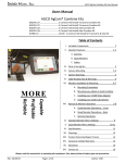
1
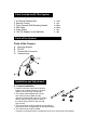
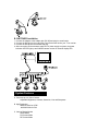
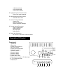
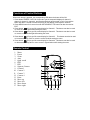
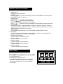
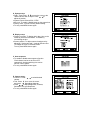
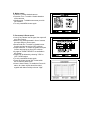
User's Manual
Model No. CVQ1000
WIRED COLOR CAMERA WITH QUAD
PROCESSOR & REMOTE CONTROL
PLEASE READ CAREFULLY AND SAVE
This manual contains important information about this product's operation. If you
are installing this product for use by others you must leave this manual -or a
copy-with the end user.
Important!
Please read this booklet carefully before installing or using these units.
WARNING-These units should ONLY be opened by an authorized technician if
service is required.
Safety Precautions
For correct and safe operation of this system, it is essential that installers,
end-users and service technicians should follow all safety procedures outlined in
this manual. Specific Warning and Caution statements (and/or symbols) are
marked on the units where needed.
Warning and Caution Statements
"WARNING" indicates a situation where failure to follow proper procedures can
cause personal injury. "CAUTION" indicates a situation where failure to follow
proper procedures can cause damage to the equipment.
Parts Included with This System
1. 4 Channel Switcher Box
2. Remote Control
3. Color Camera With Mounting bracket
4. 60ft Cable
5. Video Cable
6. 12V DC Adaptor for the Switcher
x 1 set
x 1 pc
x 4 pcs
x 4 pcs
x 1 pc
x 1 pc
Parts of the System
Parts of the Camera
A.
B.
C.
D.
Mounting bracket
IR LED
Camera Din Connector
Camera Lens
Installation and Adjustment
A. Camera Installation
1. Install or mount the camera at the desired
location. Do not place camera in a location
subject to direct sunlight or bright light.
2. The coaxial cable supplied has one end
with a DIN connector (Male) and the
opposite end with a DIN connector (Female).
Slowly insert the DIN plug into the back of
the camera being careful to align the DIN
plug correctly.
3. The camera body could be adjusted up and down by
loosening screw A and tightening up at desired angle B.
4. The camera body could be rotated
around the mounting bracket D. by adjusting screw C for any direction (360 degree).
B. SWITCHER Installation
1. Connect the adaptor to the adaptor jack [DC IN] and plug it to a wall outlet.
2. Connect the DIN plug to the output jack, connect the other end to your TV or monitor.
3. Connect the DIN jack to the camera DIN plug.
4. After connecting all the cameras; apply DC12V power supply to system, the power
indication LED will light up and indicate camera number on channel display LED.
System Features
A. Connects up to 4 Video Camera
Adjustable Brightness, Contrast, Saturation, Hue and Sharpness
B. High Resolution
860X525 60Hz for NTSC
860X625 50Hz for PAL
C. Various Display Modes
QUAD Mode
Full Screen Mode
PIP Screen Mode
1 PIP Screen Mode
2 PIP Screen Mode
Auto Sequence Mode
D. High Performance Freeze Function
Flicker Free Image Captured
E. High Performance Zoom Function
Selectable Zoom Area
F. Various Overlay Information
Camera Title
Real Time and Date
Alarm/Loss/Motion Message
G. Provide Various Event Input
Video Loss Detection
Motion Detection
60 Event Report
Built-in Buzzer
H. Power Jack Connection
DC 12V/1A, 2.1mm Jack, Center is positive.
Description Of Control
Front panel.
1. Power Led.
2. Zoom Led.
3. Freeze / Auto scan Led.
4. Ok / Enter button.
5. Freeze / Auto scan button.
6. Infrared ray receiver.
7. Camera 1 button.
8. Camera 2 button.
9. Camera 3 button.
10. Camera 4 button.
11. Quad / Menu / ESC
12. Output jack to monitor or TV Video input
13. - 16. Camera connector
17. Adapter jack
Functions of Control Buttons
When each button is pressed, the corresponding LED above the button will be ON.
1. Press button FREEZE / AUTO for 3 second to get the sequential displays of channel 1,
channel 2, channel 3, channel 4, and Quad respectively and proceed in cycle. Or press the
button less than 1 second to freeze the picture on the display, press again to unfreeze.
2. Press MENU button for 3 second to enter SETUP MENU. This button can also be used as
EXIT.
3. Press button
(C1) to get full screen display for Channel 1. This button can also be used
to move the cursor up/left while setting the menu.
4. Press button
(C2) to get full screen display for Channel 2. This button can also be used
to move the cursor down/right while setting the menu.
5. Press button
(C3) to get full screen display for Channel 3. This button can also be used
to increase the setup value or move the cursor left while setting the menu.
6. Press button
(C4) to get full screen display for Channel 4. This button can also be used
to decrease the setup value or move cursor in right direction while setting the menu.
Remote Control
1.
2.
3.
4.
5.
6.
7.
8.
9.
10.
11.
12.
13.
14.
15.
16.
17.
Menu
Freeze
Zoom
Auto
Quad. mode
PIP 2
PIP 1
Separate Camera
Camera 1
Camera 2
Camera 3
Camera 4
Enter
Move up
Move left
Move down
Move right
Remote Control Functions:
1. MENU button:
Please see menu setup section.
2. FREEZE button:
Press any channel to get full screen display, and then press FREEZE to freeze the picture.
Press FREEZE again to unfreeze.
3. ZOOM button:
Press ZOOM button to achieve zoom in display.
Press
buttons to choose zoom area.
Press Zoom button again to achieve zoom in display.
Press
buttons to get full area display or press ZOOM to re-choose zoom area
4. AUTO button:
Press AUTO to get the sequential displays of channel 1, channel 2, channel 3, channel 4,
and Quad respectively and proceed in cycle. Make sure that each channel is in a state of
ON while setting auto sequence in the menu.
5. QUAD. button:
Press QUAD button while in full screen mode display to display pictures in quad.
6/7. PIP button:
Press PIP button to get PIP (picture in picture display). Channel 1 is the default for Full
screen, and Channel 2 is the default for Sub-screen.
8. Separate cameras button:
Press to view 2 cameras at same time
9. Camera 1 button:
Press to view full screen of camera 1
10. Camera 2 button:
Press to view full screen of camera 2
11. Camera 3 button:
Press to view full screen of camera 3
12. Camera 4 button:
Press to view full screen of camera 4
Menu Setup
Press MENU to setup the menu at any mode.
1. How to set the menu:
y Press MENU to enter main menu.
y Press
buttons to move the highlight
section and choose the desired section. Press OK
to enter the desired section. To exit, press MENU
button again.
A. System setup:
y Date / Time: Press
to move the cursor to the
desired section wish to adjust. Press
to
adjust the section.
y System Format: Choose PAL / NTSC
y Key lock: To enable / disable button on the system box.
y Factory reset: To reset to factory default setting.
y To exit, press MENU button again.
B. Display setup:
y Display on screen: To display title / date / time on the
screen by check the box beside. To disable by
un-checking the box.
y Screen position: To adjust camera viewing area by
adjusting X (horizontal) and Y (vertical). Border color:
To change the color or camera's border.
To exit, press MENU button again.
C. Auto sequence:
y To enable or disable auto sequence function.
Each channel can be set to ON or OFF
respectively. And the switching time can be
set from 1sec to 99sec..
y To exit, press MENU button again.
D. Camera setup:
y Camera 1: Press
to switch desired
camera.
y Title: Press
to move the cursor,
and press
to adjust character.
y Press
to adjust Brightness, Contrast,
Saturation, Hue and Sharpness.
y To exit, press MENU button again.
E. Motion setup:
y Camera 1: Choose desired camera.
y Detection Time: To enable / disable detection
of the cameras.
y Masking area: To disable some area you wish
not to detect.
y To exit, press MENU button again.
F. Event setup & Event report:
y Loss: If any camera loss its signal, the report will
go to Event report.
y Motion: Any motion detected in front of camera,
the report will go to Event report.
y Buzzer hold time: To enable or disable buzzer
function and can be set from OFF to 99 sec..
y Report hold time: To enable or disable the report
function and can be set from OFF to 99 sec.
y 6 pages of "EVENT REPORT" are available in
this system.
y Report can be deleted by choosing "YES" on
LIST CLEAR section.
y To exit, press MENU button again.
y Press any button except "OK" on the switch
box to clear the alarm noise.
y Alarm / Alarm Polarity: To enable the Power-On
alarm, all 4 alarm checks should be ticked
together with Alarm Polarity to be set "High".
Product Specification
Camera
Remote Control/Switcher
Frequency
N/A
310/434 MHz (switcher)
Channel Scan Period
IR LED
Video Format
H Resolution
Operation Temp
Power Consumption
Power Supply
Video Input
Video Output
Size (mm)
Accessories
N/A
11
NTSC/PAL
330 TV Lines
-10~50oC
0.22W
From Switcher
N/A
1 Vp-p/75 ohm
105x55x86 mm
60ft Cable for camera
1-99sec (adjustable)
N/A
NTSC/PAL
N/A
N/A
100mA
DC 12V /1A Adapter
DIN x 4
DIN x 1
218x202x44 mm
DC 12V DC/1A Adapter
Camera Module
Lens
6.0mm/ F2.0 Fixed Focus
Image Sensor
1/3'' CMOS
Pixel
Resolution
Illumination
E Shutter Speed
S/N Ratio
860x525 60Hz (NTSC), 860x625 50Hz (PAL)
330 TV Lines
< 0 LUX w/ F2.0 Fixed Focus (30 feet)
1/60 to 1/15,000 second
>48db