1
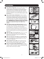
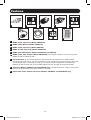
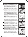
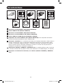
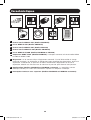
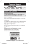
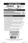
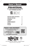
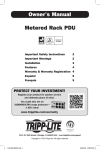
Owner’s Manual
Rack PDU
Metered Models:
PDUMV15 and PDUMV20
Basic Models:
PDUV15 and PDUV20
Important Safety Instructions
2
Important Warnings
2
Installation3
Features4
Warranty & Warranty Registration 5
Español6
Français11
1111 W. 35th Street, Chicago, IL 60609 USA • www.tripplite.com/support
Copyright © 2014 Tripp Lite. All rights reserved.
1
14-02-333-932781.indb 1
3/26/2014 2:11:12 PM
Important Safety Instructions
SAVE THESE INSTRUCTIONS
This manual contains instructions and warnings that should be
followed during the installation, operation and storage of this
product. Failure to heed these instructions and warnings will void the
product warranty.
Important Warnings
• The PDU provides convenient multiple outlets but it DOES NOT provide surge or line noise
protection for connected equipment.
• The PDU is designed for indoor use only in a controlled environment away from excess moisture, temperature extremes, conductive contaminants, dust or direct sunlight.
• Do not connect the PDU to an ungrounded outlet or extension cords or adapters that eliminate
the connection to ground.
• Use of this equipment in life support applications where failure of this equipment can
reasonably be expected to cause the failure of the life support equipment or to significantly
affect its safety or effectiveness is not recommended. Do not use this equipment in the
presence of a flammable anesthetic mixture with air, oxygen or nitrous oxide.
• The power requirement for each piece of equipment connected to the PDU must not exceed the
individual outlet’s load rating.
• The total power requirement for equipment connected to the PDU must not exceed the
maximum load rating for the PDU.
• Do not drill into or attempt to open any part of the PDU housing. There are no user-serviceable
parts inside.
• Do not attempt to modify the PDU, including the input plugs and power cables.
• Do not attempt to use the PDU if any part of it becomes damaged.
• Do not attempt to mount the PDU to an insecure or unstable surface.
• Never attempt to install electrical equipment during a thunderstorm.
2
14-02-333-932781.indb 2
3/26/2014 2:11:12 PM
Installation
1A Zero U Rack Configuration. Attach the three mounting clips
supplied with the PDU to the rack enclosure using the
included hardware. The mounting clips should be attached
along a vertical plane at equidistant points which roughly
correspond to the center and ends of the PDU. The exact
mounting configuration may vary depending on the rack and
enclosure. If possible, use pre-existing mounting points within
the enclosure.
1A
1B Wall or Under-Counter Configuration. Attach the three
mounting clips supplied with the PDU to a wall or similar flat,
secure surface using the included hardware. The mounting
clips should be attached along a vertical or horizontal plane
at equidistant points which roughly correspond to the center
and ends of the PDU. If possible, use pre-existing mounting
points. WARNING: Do not attempt to mount the PDU with
the outlets facing downward; the mounting clips are not
designed to support the weight of the PDU in that
manner.
1B
1C
1C Zero U Rack Configuration (Mounting Buttons). Attach
the included mounting buttons to the PDU. Position the PDU
as desired in the rack enclosure, align the buttons with the
rack mounting slots, and slide the PDU into position.
Note: Regardless of configuration, the user must determine
the fitness of hardware and procedures before mounting. The
PDU and included hardware are designed for common rack
and rack enclosure types and may not be appropriate for all
applications.
2
PDUMV15 and
PDUV15
2 Attach the PDU to the mounting clips. Using an assistant,
place a rear corner of the PDU at an inside edge of the
mounting clips, pivot the PDU toward the alternate inside
edge and snap into place.
3 Attach the input plug of the PDU to a grounded outlet.
Insert the plug directly into a grounded outlet that does not
share a circuit with a heavy electrical load (such as an air
conditioner or refrigerator).
3
PDUV20
3
PDUMV20
4 Attach equipment to the PDU. Do not exceed the load
rating of the PDU. The total electrical current used by the
PDU will be displayed on the digital meter in amperes.
5 Optional Installation (Model PDUMV20 Only). The PDU
includes an adapter that converts the L5-20P input plug to a
5-20P input plug. The adapter is optional; the PDU will work
properly without connecting the adapter.
4
3
14-02-333-932781.indb 3
5
PDUMV20 only
3/26/2014 2:11:14 PM
Features
1
2
6
4
3
8
7
5
9
1 NEMA 5-15P Input Plug (Model PDUMV15)
2 NEMA 5-15R Outlets (Model PDUMV15)
3 NEMA 5-20P Input Plug (Model PDUV20)
4 NEMA L5-20P Input Plug (Model PDUMV20)
5 NEMA 5-15/20R Outlets (Models PDUMV20 and PDUV20)
6 NEMA 5-20P Plug Adapter (Model PDUMV20): The adapter converts the input plug from
NEMA L5-20P to NEMA 5-20P.
7 Circuit Breaker: If the current drawn by the equipment connected to the PDU exceeds
the Maximum Load Rating, the circuit breaker will trip to prevent possible damage. When the
circuit breaker trips, its plunger will pop up. Disconnect excess equipment and allow the
breaker to cool at least one minute before depressing the plunger to reset the breaker.
8 Ammeter (Models PDUMV15 and PDUMV20 only): The total electrical current used by the
PDU will be displayed on the digital meter in amperes.
9 Illuminated Power Switch with Cover (Models PDUMV15 and PDUMV20 only)
4
14-02-333-932781.indb 4
3/26/2014 2:11:16 PM
Warranty & Warranty Registration
LIMITED WARRANTY
Seller warrants this product, if used in accordance with all applicable instructions, to be free from original defects in material and
workmanship for a period of 5 years (except internal UPS system batteries outside USA and Canada, 1 year) from the date of initial
purchase. If the product should prove defective in material or workmanship within that period, Seller will repair or replace the
product, in its sole discretion. Service under this Warranty can only be obtained by your delivering or shipping the product (with all
shipping or delivery charges prepaid) to: Tripp Lite, 1111 W. 35th Street, Chicago, IL 60609 USA. Seller will pay return shipping
charges. Visit www.tripplite.com/support before sending any equipment back for repair.
THIS WARRANTY DOES NOT APPLY TO NORMAL WEAR OR TO DAMAGE RESULTING FROM ACCIDENT, MISUSE, ABUSE OR NEGLECT.
SELLER MAKES NO EXPRESS WARRANTIES OTHER THAN THE WARRANTY EXPRESSLY SET FORTH HEREIN. EXCEPT TO THE EXTENT
PROHIBITED BY APPLICABLE LAW, ALL IMPLIED WARRANTIES, INCLUDING ALL WARRANTIES OF MERCHANTABILITY OR FITNESS,
ARE LIMITED IN DURATION TO THE WARRANTY PERIOD SET FORTH ABOVE; THIS WARRANTY EXPRESSLY EXCLUDES ALL
INCIDENTAL AND CONSEQUENTIAL DAMAGES. (Some states do not allow limitations on how long an implied warranty lasts, and
some states do not allow the exclusion or limitation of incidental or consequential damages, so the above limitations or exclusions
may not apply to you. This Warranty gives you specific legal rights, and you may have other rights which vary from jurisdiction to
jurisdiction).
WARNING: The individual user should take care to determine prior to use whether this device is suitable, adequate or safe for the
use intended. Since individual applications are subject to great variation, the manufacturer makes no representation or warranty as
to the suitability or fitness of these devices for any specific application.
WARRANTY REGISTRATION
Visit www.tripplite.com/warranty today to register the warranty for your new Tripp Lite product. You’ll be automatically entered into a
drawing for a chance to win a FREE Tripp Lite product!*
* No purchase necessary. Void where prohibited. Some restrictions apply. See website for details.
Regulatory Compliance Identification Numbers
For the purpose of regulatory compliance certifications and identification, your Tripp Lite product has been assigned a unique series
number. The series number can be found on the product nameplate label, along with all required approval markings and
information. When requesting compliance information for this product, always refer to the series number. The series number should
not be confused with the marking name or model number of the product.
The policy of Tripp Lite is one of continuous improvement. Specifications are subject to change without notice.
1111 W. 35th Street, Chicago, IL 60609 USA • www.tripplite.com/support
5
14-02-333-932781.indb 5
3/26/2014 2:11:17 PM
Manual del propietario
PDU para montaje en rack
(bastidor)
Modelos con amperímetros:
PDUMV15 y PDUMV20
Modelos básicos:
PDUV15 y PDUV20
CERTIFICADO
POR
UL 60950
Instrucciones de seguridad importantes
7
Advertencias importantes
7
Instalación8
Características9
Garantía10
English6
Français11
1111 W. 35th Street, Chicago, IL 60609 USA • www.tripplite.com/support
© 2014 Tripp Lite. Todos los derechos reservados.
6
14-02-333-932781.indb 6
3/26/2014 2:11:18 PM
Instrucciones de seguridad importantes
GUARDE ESTAS INSTRUCCIONES
Este manual contiene instrucciones y advertencias que deben
seguirse durante la instalación, operación y almacenamiento de este
producto. De no seguirlas, se anulará la garantía del producto.
Advertencias importantes
• La PDU proporciona cómodas salidas múltiples, pero NO proporciona protección contra
sobretensión o ruido en la línea al equipo conectado.
• La PDU está diseñada sólo para empleo en interiores en un ambiente controlado, lejos del
exceso de humedad, temperaturas extremas, contaminantes conductores, polvo o luz solar
directa.
• No conecte la PDU a una salida sin conexión a tierra ni a cables de extensión o adaptadores
que eliminen la conexión a tierra.
• El uso de este equipo en aplicaciones de soporte de vida en donde la falla de este equipo
pueda razonablemente hacer suponer que causará fallas en el equipo de soporte de vida o
afecte significativamente su seguridad o efectividad, no está recomendado. No use este equipo
en la presencia de una mezcla anestésica inflamable con aire, oxigeno u óxido nitroso.
• El requisito de potencia de cada equipo conectado a la PDU no debe exceder la capacidad de
carga individual de la salida.
• El requisito de potencia total para el equipo conectado a la PDU no debe exceder la máxima
capacidad de carga para la PDU.
• No taladre ni trate de abrir ninguna parte de la cubierta de la PDU. No hay partes en su interior
que requieran mantenimiento por parte del usuario.
• No intente modificar la PDU, incluyendo los enchufes de entrada y los cables de alimentación.
• No intente usar la PDU si alguno de sus componentes está dañado.
• No intente montar la PDU en una superficie insegura o inestable.
• Nunca intente instalar equipos eléctricos durante una tormenta eléctrica.
7
14-02-333-932781.indb 7
3/26/2014 2:11:18 PM
Instalación
1A
Configuración del rack (bastidor) de cero U. Fije los tres
sujetadores de montaje suministrados con la PDU a la caja
del rack (bastidor) usando los materiales incluidos. Los
sujetadores de montaje deben fijarse a lo largo de un plano
vertical en puntos equidistantes que correspondan
aproximadamente al centro y los extremos de la PDU. La
exacta configuración de montaje puede variar dependiendo
del rack (bastidor) y la caja. Si es posible, use puntos de
montaje previamente existentes dentro de la caja.
1A
1B Configuración para pared o debajo de mostrador. Fije los
tres sujetadores de montaje suministrados con la PDU a una
pared o superficie plana similar usando los materiales
incluidos. Los sujetadores de montaje deben fijarse a lo largo
de un plano vertical u horizontal en puntos equidistantes que
correspondan aproximadamente al centro y los extremos de
la PDU. Si es posible, use puntos de montaje previamente
existentes. ADVERTENCIA: No intente montar la PDU con
las salidas orientadas hacia abajo; los sujetadores de
montaje no están diseñados para soportar el peso de la
PDU de esa manera.
1B
1C
1C Configuración para bastidor Cero U (Botones de
Montaje). Fije los botones de montaje, incluidos, al PDU.
Coloque el PDU en la posición deseada en el bastidor, alinee
los botones con las ranuras de montaje del bastidor, deslice
el PDU para posicionarlo correctamente.
2
Nota: Independientemente de la configuración, el usuario
debe determinar la idoneidad de los materiales y accesorios
así como de los procedimientos antes del montaje. La PDU y
el material incluido están diseñados para racks (bastidores) y
cajas de rack (bastidor) comunes, y pueden no ser
apropiados para todas las aplicaciones.
PDUMV15 and
PDUV15
2 Fije la PDU a los sujetadores de montaje. Con la ayuda
de otra persona, coloque una esquina posterior de la PDU en
un borde interior de los sujetadores de montaje, gire la PDU
hacia el borde interior opuesto y colóquela a presión en su
posición.
3
PDUV20
3
PDUMV20
3 Conecte el enchufe de entrada de la PDU a un contacto
conectado a tierra. Inserte el enchufe directamente en una
toma de corriente alterna conectada a tierra que no
comparta el circuito con alguna carga eléctrica pesada
(como un aire acondicionado o una refrigeradora).
4 Conecte equipos a la PDU. Tenga cuidado de no exceder la
capacidad de carga de la PDU. La corriente eléctrica total
usada por la unidad de distribución de potencia (PDU) será
mostrada en el medidor digital, en amperios.
4
5 Instalación opcional (Modelo PDUMV20 Solamente). La
PDU incluye un adaptador que convierte el enchufe de
entrada L5-20P en un enchufe de entrada 5-20P El
adaptador es opcional; la PDU trabajará apropiadamente sin
conectarla al adaptador.
8
14-02-333-932781.indb 8
5
PDUMV20 only
3/26/2014 2:11:19 PM
Características
1
2
6
4
3
8
7
5
9
1 Enchufe de entrada NEMA 5-15P (Modelo PDUMV15)
2 Salidas NEMA 5-15R (Modelo PDUMV15)
3 Enchufe de entrada NEMA 5-20P (Modelo PDUV20)
4 Enchufe de entrada NEMA L5-20P (Modelo PDUMV20)
5 Salidas NEMA 5-15/20R (Modelo PDUMV20 y PDUV20)
6 Adaptadore de enchufe NEMA 5-20P (Modelo PDUMV20): Este adaptador convierte el
enchufe de entrada de NEMA L5-20P a NEMA 5-20P. 7 Interruptor automático: Si la corriente consumida por el equipo conectado al PDU excede la
máxima capacidad de carga, el interruptor automático disparará para evitar posibles daños.
Cuando un interruptor automático dispara, su émbolo se extiende. Desconecte el equipo en
exceso y permita que el interruptor automático se enfríe un minuto antes de presionar el
émbolo para restablecer el interruptor automático. 8 Amperímetro (Modelos PDUMV15 y PDUMV20 sólo): La corriente eléctrica total usada por
la unidad de distribución de potencia (PDU) será mostrada en el medidor digital, en amperios. 9 Interruptor de alimentación iluminado, con cubierta (Modelos PDUMV15 y PDUMV20
sólo)
9
14-02-333-932781.indb 9
3/26/2014 2:11:20 PM
Garantía
GARANTÍA LIMITADA
El vendedor garantiza que este producto, si se emplea de acuerdo con todas las instrucciones aplicables, no tendrá defectos en
materiales ni mano de obra por un período de 5 años (salvo para baterías internas del UPS fuera de EE.UU. y Canadá, 1 año) a
partir de la fecha de compra. Si se verifica que el producto tiene defectos en los materiales o en la mano de obra dentro de dicho
período, el vendedor reparará o reemplazará el producto, a su sola discreción. Sólo puede obtenerse servicio bajo esta garantía,
entregando o despachando el producto (con todos los cargos de despacho o entrega pagados por adelantado) a: Tripp Lite, 1111
W. 35th Street, Chicago, IL 60609 USA. El vendedor pagará los cargos de despacho del retorno. Visite www.tripplite.com/support
antes de enviar algún equipo para reparación.
ESTA GARANTÍA NO SE APLICA AL DESGASTE NORMAL O A DAÑOS RESULTANTES DE UN ACCIDENTE, USO INADECUADO,
MALTRATO O NEGLIGENCIA. EL VENDEDOR NO EXPRESA NINGUNA OTRA GARANTÍA DISTINTA DE LA ESTABLECIDA EN ESTE
DOCUMENTO EN FORMA EXPLÍCITA. EXCEPTO HASTA EL GRADO PROHIBIDO POR LAS LEYES APLICABLES, TODAS LAS GARANTÍAS
IMPLÍCITAS, INCLUYENDO TODAS LAS GARANTÍAS DE COMERCIABILIDAD O IDONEIDAD, ESTÁN LIMITADAS EN DURACIÓN AL
PERÍODO DE GARANTÍA ESTABLECIDO MÁS ARRIBA; Y ESTA GARANTÍA EXCLUYE EXPRESAMENTE TODOS LOS DAÑOS
INCIDENTALES E INDIRECTOS. (Algunos estados no permiten limitaciones sobre la duración de una garantía implícita, y algunos
estados no permiten la exclusión o limitación de daños incidentales o emergentes, de modo que las limitaciones o exclusiones de
arriba pueden no aplicarse a usted. Esta garantía le da derechos legales específicos, pero usted puede tener otros derechos que
varían de jurisdicción a jurisdicción.)
ADVERTENCIA: El usuario individual debe encargarse de determinar antes de usarlo, si este dispositivo es apropiado, adecuado o
seguro para el uso proyectado.Ya que las aplicaciones individuales están sujetas a gran variación, el fabricante no declara ni
garantiza en lo que se refiere a la idoneidad o aptitud de estos dispositivos para ninguna aplicación específica.
Cumplimiento de las normas de los números de identificación
Para fines de identificación y certificación del cumplimiento de las normas, su producto Tripp Lite tiene asignado un número de
serie único. Puede encontrar el número de serie en la etiqueta de la placa de identificación del producto, junto con los símbolos
de aprobación e información requeridos. Al solicitar información sobre el cumplimiento de las normas para este producto, siempre
mencione el número de serie. El número de serie no debe ser confundido con el nombre de identificación ni con el número de
modelo del producto.
Tripp Lite tiene una política de mejoramiento continuo. Las especificaciones están sujetas a cambio sin previo aviso.
1111 W. 35th Street, Chicago, IL 60609 USA • www.tripplite.com/support
10
14-02-333-932781.indb 10
3/26/2014 2:11:20 PM
Manual du propriétaire
Unité de distribution
d’alimentation (PDU) en bâti
Modèles avec compteur :
PDUMV15 et PDUMV20
Modèles fondamentaux :
PDUV15 et PDUV20
TESTÉ POUR
UL 60950
Importantes consignes
de sécurité
12
Importantes mises en garde
12
Installation13
Caractéristiques14
Garantie15
English1
Español6
1111 W. 35th Street, Chicago, IL 60609 USA • www.tripplite.com/support
© 2014 Tripp Lite. Tous droits réservés.
11
14-02-333-932781.indb 11
3/26/2014 2:11:22 PM
Importantes consignes de sécurité
CONSERVER CES DIRECTIVES
Ce manuel contient des instructions et des mises en garde que vous
devez respecter durant l’installation, l’utilisation et l’entreposage de
ce produit. Le non-respect de ces instructions et mises en garde
annulera la garantie du produit.
Importantes mises en garde
• L’unité PDU offre de nombreuses prises pratiques, mais elle N’offre PAS de protection contre les
surtensions transitoires et les parasites à l’équipement connecté
• L’unité PDU est conçue pour un usage en environnement contrôlé, à l’abri de l’humidité
excessive, des températures extrêmes, des contaminants conducteurs, de la poussière ou de la
lumière directe du soleil.
• Ne pas connecter l’unité PDU à une prise sans mise à la terre ou à des cordons prolongateurs
ou des adaptateurs qui éliminent la mise à la terre.
• Il est déconseillé d’utiliser cet équipement dans des applications médicales où une panne de
cet équipement pourrait normalement provoquer la panne de l’équipement de survie ou altérer
notablement sa sécurité ou son efficacité. Ne pas utiliser cet équipement en présence d’un
mélange anesthétique inflammable avec de l’air, de l’oxygène ou de l’oxyde nitreux.
• La demande d’alimentation pour chaque pièce d’équipement connectée à l’unité PDU ne doit
pas dépasser la charge nominale d’une prise individuelle.
• La demande totale d’alimentation pour l’équipement connectée à l’unité PDU ne doit pas
dépasser la charge nominale maximale pour l’unité PDU.
• Ne jamais percer ou essayer d’ouvrir une quelconque partie du boîtier de l’unité PDU. Aucune
pièce interne ne peut être réparée par l’utilisateur.
• Ne pas essayer de modifier l’unité PDU, y compris les fiches d’entrée et les câbles
d’alimentation.
• Ne pas essayer d’utiliser l’unité PDU, si une de ses pièces est endommagée.
• Ne pas essayer de monter l’unité PDU sur une surface peu sûre ou instable.
• Ne jamais essayer de d’installer un équipement électrique pendant un orage.
12
14-02-333-932781.indb 12
3/26/2014 2:11:22 PM
Installation
1A
1B
1C
Configuration du bâti Zero U. Fixer les trois pattes de
montage fournies avec l’unité PDU au boîtier du bâti à l’aide
de la quincaillerie jointe. Il faut fixer les pattes de montage le
long d’un plan vertical, à des points équidistants qui
correspondent en gros au centre et aux extrémités de l’unité
PDU. La configuration exacte du montage dépend du bâti et
du boîtier. Si possible, utiliser des points de fixation
préexistants dans le boîtier.
Configuration murale ou sous comptoir. Fixer les trois
attaches de montage fournies avec l’unité PDU à un mur ou
une surface semblable, plane et solide, à l’aide de la
quincaillerie jointe. Il faut fixer les pattes de montage, le long
d’un plan vertical ou horizontal à des points équidistants qui
correspondent en gros au centre et aux extrémités de l’unité
PDU. Si possible, utiliser des points de fixation préexistants.
MISE EN GARDE : Ne pas essayer de monter l’unité PDU
avec les prises faisant face au sol, les pattes de
montage ne sont pas conçues pour supporter le poids
de l’unité de cette façon.
1B
1C
Configuration en bâti zéro U (Boutons de montage). Fixer
les boutons de montage inclus à l’unité de distribution.
Placer l’unité de distribution comme désiré dans la baie,
aligner les boutons avec les fentes de montage du bâti et
glisser l’unité en place.
Nota : Sans tenir compte de la configuration, l’utilisateur doit
déterminer la compatibilité de la quincaillerie et les
procédures avant d’effectuer l’installation. L’unité PDU et la
quincaillerie incluse sont conçues pour des types de bâti et
boîtier courants et peuvent ne pas convenir à toutes les
applications.
2
1A
Fixer l’unité PDU aux pattes de montage. À l’aide d’un
assistant, placer un coin arrière de l’unité à un bord intérieur
de la patte de montage, faire pivoter l’unité vers l’autre bord
et fixer en place.
3
Fixer le fiche d’entrée de l’unité PDU à une prise mise à
la terre. Insérer la fiche directement dans une prise CA
correctement mise à la terre, qui ne partage pas de circuit
supportant une lourde charge électrique (comme un
climatiseur ou un réfrigérateur).
4
Fixer l’équipement à l’unité PDU. Faire attention de ne pas
dépasser la charge nominale de l’unité PDU. La totalité du
courant électrique utilisée par la PDU sera affichée en
ampères au compteur numérique.
5
Installation optionnelle (Modèle PDUMV20 Seulement).
La PDU comprend un adaptateur qui convertit la fiche
d’entrée L5-20P en fiche d’entrée 5-20P. L’adaptateur est en
option; la PDU fonctionnera correctement sans être
connectée à l’adaptateur.
13
14-02-333-932781.indb 13
2
PDUMV15 and
PDUV15
3
PDUV20
3
PDUMV20
4
5
PDUMV20 only
3/26/2014 2:11:24 PM
Caractéristiques
1
2
6
4
3
8
7
5
9
1 Fiche d’entrée NEMA 5-15P (Modèle PDUMV15)
2 Prises NEMA 5-15R (Modèle PDUMV15)
3 Fiche d’entrée NEMA 5-20P (Modèle PDUV20)
4 Fiche d’entrée NEMA L5-20P (Modèle PDUMV20)
5 Prises NEMA 5-15/20R (Modèle PDUMV20 et PDUV20)
6 Adaptateur NEMA 5-20P (Modèle PDUMV20) : L’adapteur convertit le fiche d’entrée NEMA
L5-20P en NEMA 5-20P. 7 Disjoncteur : Si le courant tiré par l’équipement connecté à l’unité PDU excède la charge
nominale maximale, un disjoncteur se déclenchera pour empêcher des dommages. Quand un
disjoncteur se déclenche, le poussoir se relève. Déconnecter l’équipement et laisser le
disjoncteur refroidir une minute avant de rabaisser le poussoir pour réarmer le disjoncteur. 8 Ampèremètre (Modèles PDUMV15 et PDUMV20 seulement) : La totalité du courant
électrique utilisée par la PDU sera affichée en ampères au compteur numérique.
9 Interrupteur lumineux avec capuchon (Modèles PDUMV15 et PDUMV20 seulement)
14
14-02-333-932781.indb 14
3/26/2014 2:11:25 PM
Garantie
GARANTIE LIMITÉE
Le vendeur garantit que ce produit, s’il est utilisé selon toutes les directives applicables, est exempt de défauts d’origine de
matériel et de main-d’oeuvre pour une période de 5 ans (à l’exception des batteries interne du système UPS hors des É. U. et du
Canada, 1 an) à partir de la date initiale d’achat. Si le produit s’avère défectueux en matériel ou en main-d’oeuvre durant cette
période, le vendeur réparera ou remplacera le produit à sa discrétion. Vous pouvez obtenir un service selon cette garantie
seulement en livrant ou en expédiant le produit (avec les frais d’expédition et de livraison prépayés) à : Tripp Lite, 1111 W. 35th
Street, Chicago, IL 60609 USA. Le vendeur paierai les frais d’expédition de retour. Visitez www.tripplite.com/support avant
d’envoyer un équipement pour réparations.
CETTE GARANTIE NE S’APPLIQUE PAS A UNE USURE NORMALE OU UN ENDOMMAGEMENT RESULTANT D’ACCIDENT, UTILISATION
ERRONEE, ABUS OU NEGLIGENCE. LE VENDEUR N’OFFRE AUCUNE GARANTIE EXPRESSE AUTRE QUE LA GARANTIE
EXPRESSEMENT ETABLIE DANS LA PRESENTE. SAUF DANS LA MESURE PROHIBEE PAR LA LOI APPLICABLE, TOUTES LES
GARANTIES IMPLICITES, INCLUANT TOUTES LES GARANTIES DE COMMERCIALISATION OU ADAPTATION, SONT LIMITEES A LA
DUREE DE LA PERIODE DE GARANTIE INDIQUEE CI-DESSUS ; ET CETTE GARANTIE EXCLUT EXPRESSEMENT TOUS LES DOMMAGES
ACCIDENTELS OU PROVOQUES. (Certains Etats ne permettent pas de limitation pour la durée de garantie implicite, et certains
Etats ne permettent pas l’exclusion ou la limitation de dommages accidentels ou provoqués, en conséquence les limitations ou
exclusions ci-dessus peuvent ne pas être applicables pour vous. Cette Garantie vous donne des droits légaux spécifiques, et vous
pouvez avoir d’autres droits variant suivant les juridictions).
AVERTISSEMENT : L’utilisateur individuel doit prendre toutes mesures pour déterminer avant utilisation si cet appareil est approprié,
adéquat ou offre toute sécurité pour l’utilisation prévue. Du fait que les applications individuelles sont sujettes à de grandes
variations, le fabricant n’assure aucune description ou garantie concernant l’aptitude ou l’adaptation de ces appareils pour toute
application spécifique.
Numéros d’identification de conformité aux règlements
À des fins de certification et d’identification de conformité aux règlements, votre produit Tripp Lite a reçu un numéro de série
unique. Ce numéro se retrouve sur la plaque signalétique du produit, avec les inscriptions et informations d’approbation requises. Lors d’une demande d’information de conformité pour ce produit, utilisez toujours le numéro de série. Il ne doit pas être confondu
avec le nom de la marque ou le numéro de modèle du produit.
La politique de Tripp Lite est celle d’une amélioration continuelle. Les spécifications peuvent être modifiées sans préavis.
15
14-02-333-932781.indb 15
3/26/2014 2:11:25 PM
1111 W. 35th Street, Chicago, IL 60609 USA • www.tripplite.com/support
14-02-333 • 93-2781_revB
16
14-02-333-932781.indb 16
3/26/2014 2:11:25 PM