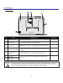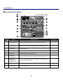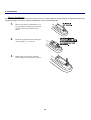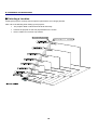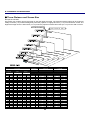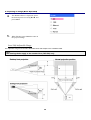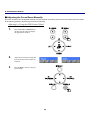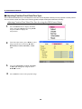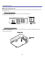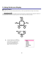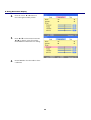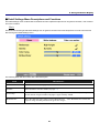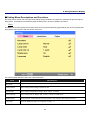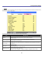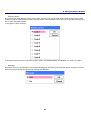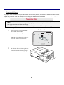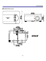
1
© SANYO Electric Co., Ltd. 2007 x DLP is a registered trademark of Texas Instruments. BrilliantColor and DynamicBlack are trademarks of Texas Instruments. x IBM is a trademark or registered trademark of International Business Machines Corporation. x Macintosh, Mac OS X and PowerBook are trademarks of Apple, Inc., registered in the U.S. and other countries. x Windows, Windows 98, Windows Me, Windows XP or Windows 2000 are trademarks or registered trademarks of Microsoft Corporation. x Trademark PJLink is a trademark applied for trademark rights in Japan, the United States of America and other countries and areas. x Other product and company names mentioned in this user's manual may be the trademarks or registered trademarks of their respective holders. Notes (1) The contents of this user’s manual may not be reprinted in part or whole without permission. (2) The contents of this user’s manual are subject to change without notice. (3) The On-Screen Menu and figures in this manual may differ slightly from the product. (4) Great care has been taken in the preparation of this user’s manual; however, should you notice any questionable points, errors or omissions, please contact us. (5) Notwithstanding article (3), SANYO will not be responsible for any claims on loss of profit or other matters deemed to result from using the Projector. To the Owner Before installing and operating the projector, read this manual thoroughly. The projector provides many convenient features and functions. Operating the projector properly enables you to manage those features and maintains it in good condition for many years to come. Improper operation may result in not only shortening the product life, but also malfunctions, fire hazard, or other accidents. If your projector seems to operate improperly, read this manual again, check operations and cable connections and try the solutions in the “Troubleshooting” section in the back of this booklet. If the problem still persists, contact the dealer where you purchased the projector or the service center. Safety Precaution WARNING: TO REDUCE THE RISK OF FIRE OR ELECTRIC SHOCK, DO NOT EXPOSE THIS APPLIANCE TO RAIN OR MOISTURE. This projector produces intense light from the projection lens. Do not stare directly into the lens as much as possible, otherwise eye damage could result. Be especially careful that children do not stare directly into the beam. Install the projector in a proper position. Otherwise it may result in fire hazard. Allowing the proper amount of space on the top, sides, and rear of the projector cabinet is critical for proper air circulation and cooling of the unit. The dimension shown here indicates the minimum space required. If the projector is to be built into a compartment or similarly enclosed, these minimum distances must be maintained. Do not cover the ventilation slot on the projector. Heat build-up can reduce the service life of your projector, and can also be dangerous. SIDE and TOP REAR CAUTION: TO REDUCE THE RISK OF ELECTRIC SHOCK, DO NOT REMOVE COVER (OR BACK). NO USER-SERVICEABLE PARTS INSIDE EXCEPT LAMP REPLACEMENT. REFER SERVICING TO QUALIFIED SERVICE PERSONNEL. THIS SYMBOL INDICATES THAT DANGEROUS VOLTAGE CONSTITUTING A RISK OF ELECTRIC SHOCK IS PRESENT WITHIN THIS UNIT. THIS SYMBOL INDICATES THAT THERE ARE IMPORTANT OPERATING AND MAINTENANCE INSTRUCTIONS IN THE USER’S MANUAL WITH THIS UNIT. If the projector is unused for an extended time, unplug the projector from the power outlet. NOTE: This symbol and recycle system are applied CAUTION ON HANGING FROM THE CEILING When hanging the projector from the ceiling, clean air intake vents, filters, or top of the projector periodically with a vacuum cleaner. If you leave the projector unclean for a long time, the cooling fans can be clogged with dust, and it may cause a breakdown. DO NOT SET THE PROJECTOR IN GREASY, WET, OR CONDITIONS SUCH AS IN A KITCHEN TO PREVENT A BREAKDOWN. IF THE PROJECTOR COMES IN CONTACT WITH OIL OR CHEMICALS, IT MAY BECOME DETERIORATED. only to EU countries and not applied to the countries in the other area of the world. Your SANYO product is designed and manufactured with high quality materials and components which can be recycled and reused. This symbol means that electrical and electronic equipment, at their end-of-life, should be disposed of separately from your household waste. Please dispose of this equipment at your local community waste collection/recycling centre. In the European Union there are separate collection systems for used electrical and electronic products. Please help us to conserve the environment we live in! WARNING: Not for use in a computer room as defined in the Standard for the Protection of Electronic Computer/Data Processing Equipment, ANSI/NFPA 75. Ne peut être utilisé dans une salle d’ordinateurs telle que définie dans la norme ANSI/NFPA 75 Standard for Protection of Electronic Computer/Data Processing Equipment. READ AND KEEP THIS USER’S MANUAL FOR LATER USE. i Safety Instructions All the safety and operating instructions should be read before the product is operated. Do not install the projector near the ventilation duct of airconditioning equipment. Read all of the instructions given here and retain them for later use. Unplug this projector from AC power supply before cleaning. Do not use liquid or aerosol cleaners. Use a damp cloth for cleaning. This projector should be operated only from the type of power source indicated on the marking label. If you are not sure of the type of power supplied, consult your authorized dealer or local power company. Follow all warnings and instructions marked on the projector. Do not overload wall outlets and extension cords as this can result in fire or electric shock. Do not allow anything to rest on the power cord. Do not locate this projector where the cord may be damaged by persons walking on it. For added protection to the projector during a lightning storm, or when it is left unattended and unused for long periods of time, unplug it from the wall outlet. This will prevent damage due to lightning and power line surges. Do not attempt to service this projector yourself as opening or removing covers may expose you to dangerous voltage or other hazards. Refer all servicing to qualified service personnel. Do not expose this unit to rain or use near water... for example, in a wet basement, near a swimming pool, etc... Unplug this projector from wall outlet and refer servicing to qualified service personnel under the following conditions: Do not use attachments not recommended by the manufacturer as they may cause hazards. a. When the power cord or plug is damaged or frayed. b. If liquid has been spilled into the projector. Do not place this projector on an unstable cart, stand, or table. The projector may fall, causing serious injury to a child or adult, and serious damage to the projector. Use only with a cart or stand recommended by the manufacturer, or sold with the projector. Wall or shelf mounting should follow the manufacturer’s instructions, and should use a mounting kit approved by the manufacturers. c. If the projector has been exposed to rain or water. d. If the projector does not operate normally by following the operating instructions. Adjust only those controls that are covered by the operating instructions as improper adjustment of other controls may result in damage and will often require extensive work by a qualified technician to restore the projector to normal operation. An appliance and cart combination should be moved with care. Quick stops, excessive force, and uneven surfaces may cause the appliance and cart combination to overturn. e. If the projector has been dropped or the cabinet has been damaged. f. When the projector exhibits a distinct change in performance-this indicates a need for service. Slots and openings in the back and bottom of the cabinet are provided for ventilation, to ensure reliable operation of the equipment and to protect it from overheating. When replacement parts are required, be sure the service technician has used replacement parts specified by the manufacturer that have the same characteristics as the original part. Unauthorized substitutions may result in fire, electric shock, or injury to persons. The openings should never be covered with cloth or other materials, and the bottom opening should not be blocked by placing the projector on a bed, sofa, rug, or other similar surface. This projector should never be placed near or over a radiator or heat register. Upon completion of any service or repairs to this projector, ask the service technician to perform routine safety checks to determine that the projector is in safe operating condition. This projector should not be placed in a built-in installation such as a bookcase unless proper ventilation is provided. Voor de klanten in Nederland Bij dit produkt zijn batterijen geleverd. Never push objects of any kind into this projector through cabinet slots as they may touch dangerous voltage points or short out parts that could result in a fire or electric shock. Never spill liquid of any kind on the projector. Wanneer dezeleeg zijn, moet u ze niet weggooien maar inleveren als KCA. ii Important Information Air Circulation Openings in the cabinet are provided for ventilation. To ensure reliable operation of the product and to protect it from overheating, these openings must not be blocked or covered. IMPORTANT! Clean the Filter Regularly!! The projector uses a lamp which generates significant heat. The cooling fans and air vents are provided to dissipate the heat by drawing air into the housing and the filter is located in the intake vents to prevent dust from getting inside of the projector. CAUTION Hot air is from the exhaust vent. When using or installing the projector, the following precautions should be taken. In order to care for the projector appropriately, regular cleaning is required. Remove any dirt or dust that has accumulated on the projector and on or in the filter. Do not put any flammable objects or spray cans near the projector, hot air is exhausted from the air vents. Keep the exhaust vent at least 3 feet (1 m) away from any objects. Do not touch peripheral parts in the exhaust vents, especially screws and metallic parts. These areas will become hot while the projector is used. Do not put anything on the cabinet. Objects put on the cabinet will not only get damaged but may also cause a fire hazard. Cooling fans are provided to cool down the projector. The fans’ running speed is changed according to the temperature inside the projector. When the “Please clean filter” message is displayed, stop using the projector immediately and clean or replace the filter. Blocking the air vents and leaving the projector uncleaned for a long time may not only damage the projector and may require costly repairs but may also cause accidents or fire. For maintenance of the filter, refer to “Option” on page 83 and “Replacing the Filters” on pages 97 – 98. Damages to the projector caused by using an un-cleaned filter or improper maintenance will void the warranty on the projector. Installing the Projector in Proper Position Install the projector properly. Improper installation may reduce the lamp lifetime and cause a fire hazard. Do not tilt the projector more than 10 degrees above and below. Do not put the projector on either side to project an image. Do not point the projector up to project an image. NO UPWARD NO SIDEWAYS Do not point the projector down to project an image. NO DOWNWARD xi Compliance Federal Communications Commission Notice This equipment has been tested and found to comply with the limits for a Class B digital device, pursuant to Part 15 of the FCC Rules. These limits are designed to provide reasonable protection against harmful interference in a residential installation. This equipment generates, uses, and can radiate radio frequency energy and, if not installed and used in accordance with the instructions, may cause harmful interference to radio communications. However, there is no guarantee that interference will not occur in a particular installation. If this equipment does cause harmful interference to radio or television reception, which can be determined by turning the equipment off and on, the user is encouraged to try to correct the interference by one or more of the following measures: Reorient or relocate the receiving antenna. Increase the separation between the equipment and receiver. Connect the equipment into an outlet on a circuit different from that to which the receiver is connected. Consult the dealer or an experienced radio/TV technician for help. Use of shielded cable is required to comply with class B limits in Subpart B of Part 15 of FCC Rules. Do not make any changes or modifications to the equipment unless otherwise specified in the instructions. If such changes or modifications should be made, you could be required to stop operation of the equipment. Model Number(s) Trade Name Responsible party Address Telephone No. : PDG-DXT10L : Sanyo : SANYO FISHER COMPANY : 21605 Plummer Street, Chatsworth, California 91311 U.S.A. : (818)998-7322 AC Power Cord Requirement The AC Power Cord supplied with this projector meets the requirement for use in the country you purchased it. AC Power Cord for the United States and Canada: AC Power Cord used in the United States and Canada is listed by the Underwriters Laboratories (UL) and certified by the Canadian Standard Association (CSA). AC Power Cord has a grounding-type AC line plug. This is a safety feature to be sure that the plug will fit into the power outlet. Do not try to defeat this safety feature. Should you be unable to insert the plug into the outlet, contact your electrician. AC Power Cord for the United Kingdom: This cord is already fitted with a modulized plug incorporating a fuse, the value of which is indicated on the pin face of the plug. Should the fuse need to be replaced, an ASTA approved BS 1362 fuse must be used of the same rating, marked thus . If the fuse cover is detachable, never use the plug with the cover omitted. If a replacement fuse cover is required, ensure it is of the same color as that visible on the pin face of the plug (i.e. red or orange). Fuse covers are available from the Parts Department indicated in your User Instructions. If the plug supplied is not suitable for your socket outlet, it should be cut off and destroyed. The end of the flexible cord should be suitably prepared and the correct plug fitted. WARNING: A PLUG WITH BARED FLEXIBLE CORD IS HAZARDOUS IF ENGAGED IN A LIVE SOCKET OUTLET. The Wires in this mains lead are colored in accordance with the following code: Green-and-yellow ············ Earth Blue ································· Neutral Brown ······························ Live As the colors of the wires in the mains lead of this apparatus may not correspond with the colored markings identifying the terminals in your plug proceed as follows: The wire which is colored green-and-yellow must be connected to the terminal in the plug which is marked by the letter E or by the safety earth symbol or colored green or green-and-yellow. The wire which is colored blue must be connected to the terminal which is marked with the letter N or colored black. The wire which is colored brown must be connected to the terminal which is marked with the letter L or colored red. WARNING: THIS APPARATUS MUST BE EARTHED. THE SOCKET-OUTLET SHOULD BE INSTALLED NEAR THE EQUIPMENT AND EASILY ACCESSIBLE. iv Table of Contents 1. INTRODUCTION ..................................................................................................................................................................................1 n WHAT’S IN THE BOX? ..........................................................................................................................................................................1 o INTRODUCTION TO THE PROJECTOR...................................................................................................................................................2 Features you’ll enjoy:........................................................................................................................................................................2 p PART NAMES OF THE PROJECTOR .....................................................................................................................................................3 Front-right View .................................................................................................................................................................................3 Top view .............................................................................................................................................................................................4 Carrying the Projector ......................................................................................................................................................................5 Bottom view .......................................................................................................................................................................................6 q TOP FEATURES ...................................................................................................................................................................................7 Lens Controls.....................................................................................................................................................................................7 OSD Controls and Status LEDs......................................................................................................................................................8 r TERMINAL PANEL FEATURES ............................................................................................................................................................10 s PART NAMES OF THE REMOTE CONTROL ........................................................................................................................................12 Battery Installation ..........................................................................................................................................................................14 Operating Range for Wireless Remote Control ..........................................................................................................................15 Remote Control Precautions .........................................................................................................................................................15 Remote Control Codes...................................................................................................................................................................15 Using the Remote Control in Wired Operation ...........................................................................................................................16 2. INSTALLATION AND CONNECTIONS .........................................................................................................................................17 n SETTING UP THE SCREEN AND THE PROJECTOR .............................................................................................................................17 o SELECTING A LOCATION....................................................................................................................................................................18 p INSTALLING OR REMOVING THE OPTIONAL LENS .............................................................................................................................19 Removing the Existing Lens From the Projector ........................................................................................................................19 Installing the New Lens ..................................................................................................................................................................20 Installing the New Lens Using the anti-theft screw ....................................................................................................................21 q THROW DISTANCE AND SCREEN SIZE ..............................................................................................................................................22 r INSTALLING THE OPTIONAL COLOR WHEEL .....................................................................................................................................24 s MAKING CONNECTIONS.....................................................................................................................................................................26 Connecting Your PC or Macintosh Computer.............................................................................................................................26 Connecting an External Monitor....................................................................................................................................................28 Connecting Your DVD Player with Component Output .............................................................................................................29 Connecting Your VCR or Laser Disc Player ...............................................................................................................................30 t CONNECTING THE SUPPLIED POWER CABLE ...................................................................................................................................31 NOTE ON THE POWER CORD ...................................................................................................................................................31 3. PROJECTING AN IMAGE (BASIC OPERATION) .......................................................................................................................32 n TURNING ON THE PROJECTOR ..........................................................................................................................................................32 Note on Startup Screen (Menu Language Select screen) ........................................................................................................33 o SELECTING AN INPUT SOURCE .........................................................................................................................................................34 p ADJUSTING THE PICTURE POSITION AND PICTURE SIZE..................................................................................................................35 Adjusting Picture Position Manually .............................................................................................................................................35 Lens Shift Adjustable Range .........................................................................................................................................................36 From the Remote Control Unit ......................................................................................................................................................37 Adjusting the Projector Level.........................................................................................................................................................38 q OPTIMIZING AN RGB IMAGE AUTOMATICALLY .................................................................................................................................39 Adjusting the Image Using AUTO PC ADJ. ................................................................................................................................39 r ADJUSTING VOLUME UP AND DOWN ................................................................................................................................................40 s TURNING OFF THE PROJECTOR ........................................................................................................................................................41 About Direct Power Off...................................................................................................................................................................42 After Use...........................................................................................................................................................................................42 viii Table of Contents 4. CONVENIENT FEATURES ..............................................................................................................................................................43 n TURNING OFF THE IMAGE AND SOUND .............................................................................................................................................43 o FREEZING A PICTURE ........................................................................................................................................................................43 p ADJUSTING THE FOCUS/ZOOM MANUALLY.......................................................................................................................................44 Adjusting by Using the OSD Control Panel.................................................................................................................................44 q CHANGING LAMP MODE ....................................................................................................................................................................45 Changing Lamp Mode by Using the Projector's OSD Control Panel ......................................................................................45 Changing Lamp Mode by Using the Remote Control ................................................................................................................46 r GETTING INFORMATION.....................................................................................................................................................................47 s ADJUSTING POSITION/TOTAL DOTS/FINE SYNC ..............................................................................................................................48 Adjusting Position/Total Dots/Fine Sync by using the OSD Control Panel ............................................................................48 Correcting Keystone by Using the Remote Control ...................................................................................................................49 t PREVENTING THE UNAUTHORIZED USE OF THE PROJECTOR ..........................................................................................................51 Locking the Projector......................................................................................................................................................................51 Unlocking the Projector ..................................................................................................................................................................53 u USING THE PHYSICAL LOCK ..............................................................................................................................................................54 Using the Kensington Lock............................................................................................................................................................54 Using the Security Chain Lock ......................................................................................................................................................54 5. USING ON-SCREEN DISPLAY.......................................................................................................................................................55 n USING THE MENUS ............................................................................................................................................................................55 Navigating the OSD ........................................................................................................................................................................55 o MENU TREE .......................................................................................................................................................................................57 p MENU ELEMENTS ..............................................................................................................................................................................59 q SOURCE MENU DESCRIPTIONS AND FUNCTIONS .............................................................................................................................60 r ADJUST MENU DESCRIPTIONS AND FUNCTIONS ..............................................................................................................................61 Image menu .....................................................................................................................................................................................61 Image options menu .......................................................................................................................................................................62 Video menu......................................................................................................................................................................................64 s DETAIL SETTINGS MENU DESCRIPTIONS AND FUNCTIONS ..............................................................................................................67 Basic .................................................................................................................................................................................................67 White balance ..................................................................................................................................................................................69 Color correction ...............................................................................................................................................................................70 t SETTING MENU DESCRIPTIONS AND FUNCTIONS .............................................................................................................................71 Basic .................................................................................................................................................................................................71 Installation ........................................................................................................................................................................................75 Network setting................................................................................................................................................................................82 Option ...............................................................................................................................................................................................83 u INFORMATION MENU DESCRIPTIONS AND FUNCTIONS.....................................................................................................................89 Usage time .......................................................................................................................................................................................89 Input ..................................................................................................................................................................................................90 Network.............................................................................................................................................................................................91 Version..............................................................................................................................................................................................92 v RESET MENU DESCRIPTIONS AND FUNCTIONS ................................................................................................................................93 6. MAINTENANCE .................................................................................................................................................................................94 n CLEANING THE PROJECTOR ..............................................................................................................................................................94 Cleaning the Cabinet ......................................................................................................................................................................94 Cleaning the Lens ...........................................................................................................................................................................94 Cleaning the Filters.........................................................................................................................................................................95 o REPLACING CONSUMABLE PARTS ....................................................................................................................................................97 Replacing the Filters .......................................................................................................................................................................97 Replacing the Lamps......................................................................................................................................................................99 Resetting the Lamp Time Counter..............................................................................................................................................101 Ordering a Replacement Lamp...................................................................................................................................................101 x Table of Contents 7. APPENDIX ........................................................................................................................................................................................102 n TROUBLESHOOTING ........................................................................................................................................................................102 Indicator Messages.......................................................................................................................................................................102 Common Problems and Solutions ..............................................................................................................................................104 Tips for Troubleshooting ..............................................................................................................................................................104 o IMAGE PROBLEMS ...........................................................................................................................................................................105 Lamp Problems .............................................................................................................................................................................105 Remote Control Problems ...........................................................................................................................................................106 Audio Problems .............................................................................................................................................................................106 p HAVING THE PROJECTOR SERVICED ..............................................................................................................................................106 8. SPECIFICATIONS ...........................................................................................................................................................................107 n PROJECTOR SPECIFICATIONS .........................................................................................................................................................107 Optical Specifications ...................................................................................................................................................................107 Electrical Specifications ...............................................................................................................................................................108 Mechanical Specifications ...........................................................................................................................................................109 Environmental Considerations ....................................................................................................................................................109 Regulations ....................................................................................................................................................................................109 Optional Parts ................................................................................................................................................................................110 o CABINET DIMENSIONS .....................................................................................................................................................................111 p PIN ASSIGNMENTS OF MINI D-SUB 15 PIN INPUT CONNECTOR ....................................................................................................112 q COMPATIBLE INPUT SIGNAL LIST ....................................................................................................................................................113 r PC CONTROL CODES AND CABLE CONNECTIONS .........................................................................................................................115 Functional Execution Command Table......................................................................................................................................115 Status Read Command Table.....................................................................................................................................................116 s SCREEN TRIGGER ...........................................................................................................................................................................117 t OPERATION USING HTTP BROWSER.............................................................................................................................................118 Overview.........................................................................................................................................................................................118 Preparation Before Use................................................................................................................................................................118 Handling of the Address for Operation by Using a Browser ...................................................................................................118 Configuring Network Settings......................................................................................................................................................119 Structure of the HTTP Server......................................................................................................................................................121 u 15 PIN GPIO CONTROL .................................................................................................................................................................123 9. TROUBLESHOOTING CHECK LIST ...........................................................................................................................................124 xi 1. Introduction n What’s in the Box? Carefully unpack the projector and check that the following items are included: PDG-DXT10L Projector Remote Control (with Two AA alkaline batteries) Power Cable (3.6m/11.8 ft.) ĺ For North America, Europe and the UK Quick Start Guide Remote Cable (10m/33ft) VGA Cable CD-ROM (This User’s manual) Anti-Theft Screw for lens x1 Security Sticker Lens Hole Cap (Installed) Contact your dealer immediately if any items are missing, appear damaged, or if the unit does not work. CAUTION Avoid using the projector in dusty environments. 1 1. Introduction o Introduction to the Projector Features you’ll enjoy: DLP projector with high resolution The combination of BrilliantColor™ and a six-segment color wheel (optional) offer a more true color reproduction. Installation Flexibility This projector has many useful functions such as powered lens shifting, ceiling and rear projection, variety of extensive optional powered lens with bayonet mount with release button, etc. Multiple Interface Terminals The projector has several interface terminals that can support various types of equipment and signals. Dual Lamp Control System The two-lamp control system offers high brightness, maintained lamp life and energy savings along with redundancy. The lamp control function offers brightness of the lamp can be selected. The power management function also reduces power consumption and maintains lamp life. Simple Computer System Setting The projector has the Multi-scan system to conform to almost all computer output signals quickly. Up to UXGA resolution can be accepted. Security Function The Security function helps you to ensure security of the projector. With the Key lock function, you can lock the operation on the top control. PIN code lock functions prevent unauthorized use of the projector. Multilanguage Menu Display Operation menu is available in 8 languages: English, German, French, Italian, Spanish, Swedish, Chinese, and Japanese. Multi-use Remote Control Use the remote control as wired or wireless. Eight remote control codes are available. 3W + 3W Stereo Speaker Built in 3W x 2 speakers are provided. Helpful Maintenance Functions The lamp and filter maintenance functions provide for better and proper maintenance of the projector. Easy maintenance cover is provided for lamp and color wheel replacement. Network-capable Through an optional Network Manager with serial port in, you can operate and control the projector. Direct Power Off and On Start The Direct Power Off function allows the projector to be turned off (even when projecting an image) using a power strip equipped with a switch and a breaker. The On Start function allows the projector to be turned on by supplied AC power. Note: Before using Direct Power Off, be sure to allow at least 20 minutes immediately after turning on the projector and starting to display an image. Also, the power cord can be removed immediately after turning off the projector. On Start manual may differ slightly from the product. On Start eliminates the need to always use the POWER (ON/STANDBY) button on the remote control or projector cabinet. 2 1. Introduction p Part Names of the Projector Front-right view ITEM LABEL DESCRIPTION SEE PAGE: 1. 2. IR receiver Receiver for IR signal from remote control Lamp cover Remove cover to replace lamp or color wheel 12 99 3. Lens control panel See Lens Controls 7 4. OSD control panel See OSD Controls and Status LEDS 8 5. 6. 7. 8. 9. I/O connector panel Connect various input devices Intake vent Lamp cooling vent – do not obstruct Speakers Built-in stereo speakers Height adjuster Adjusts level of projector Lens Remove lens cap before use 10 — — 6 — 10. Lens release button Press the release button before removing the lens — 11. Anti-Theft screw — 12. Intake vent and front filter Prevent theft of the lens Keeps the front fan free of dust – clean regularly for optimum performance – do not obstruct 95 Important: Grill openings on the projector allow for good air circulation, which keeps the projector lamp cool. Do not obstruct any of the grill openings. 3 1. Introduction Top view ITEM LABEL DESCRIPTION SEE PAGE: 1. Lens control panel See Lens Controls 7 2. Right-hand speaker Right-hand speaker — 3. Lamp cover Remove cover to replace lamp or color wheel 99 4. Exhaust vent Exhaust vent – do not obstruct — 5. OSD control panel See OSD Controls and Status LEDS 8 6. Rear intake vent Rear cooling intake – do not obstruct — 7. Left intake vent Left-hand cooling intake – do not obstruct — 8. Left-hand speaker Left-hand speaker — 4 1. Introduction Carrying the Projector Always carry your projector by the handle. Before moving or carrying the projector, disconnect the power cable and any other cables that may be attached to it. When moving the projector or when the projector is not in use, cover the lens with the lens cap. To extend the projector handle, refer to the following guide. 1. Stand the projector on its end with the control panels at the bottom. 2. Lift the handle in the direction shown until it is fully extended. Note: Stand the projector on its end by lifting the cabinet. Do not use the handle to place the projector upright. 5 1. Introduction Bottom view ITEM LABEL DESCRIPTION SEE PAGES: 1. Height adjusters Adjust projection height 38 2. Intake vent Color wheel cooling vent – do not obstruct — 3. Front filter Keep the fan free of dust – clean regularly for optimum performance 95 4. Ceiling support holes Contact your dealer for information on mounting the projector on a ceiling — 5. Security chain opening Attach anti-theft device – see u Using the Physical Lock 54 6. Rear filter 7. 95 Side filter Keep the fans free of dust – clean regularly for optimum performance CAUTION With ceiling installation, use approved mounting hardware & M4 screws; maximum depth of screw: 12 mm; distance from ceiling/ wall: 20 cm (0.7 feet) for proper ventilation; distance from fluorescent lamps: at least 1 m (3 feet) front and back of the projector. For permanent installations, follow local codes. 6 1. Introduction q Top Features Lens Controls ITEM LABEL 1. ZOOM 2. UP CURSOR 3. RIGHT CURSOR 4. DOWN CURSOR 5. LEFT CURSOR 6. FOCUS DESCRIPTION Increase/decrease projected image size SEE PAGE: 44 Move image left, right, up, or down Focus the projected image 7 44 1. Introduction OSD Controls and Status LEDs ITEM LABEL DESCRIPTION SEE PAGE: 1. MENU Open / Close the OSD 55 2. UP/ DOWN/ LEFT/ RIGHT BUTTONS Navigate and change settings in the OSD 55 3. RIGHT CURSOR/ VOLUME INCREASE Increase volume 40 4. CANCEL Exit the On-Screen Display (OSD) 55 5. INPUT Change or select the input device 34 6. ON/STAND-BY Turn the projector on or off (main power switch must be turned on first). Press to place the projector in standby mode. 39 7. LAMP 2 (LED) Green See Indicator Messages Flashing 8 102 1. Introduction ITEM 8. LABEL DESCRIPTION Green LAMP 1 (LED) SEE PAGE: See Indicator Messages 102 See Indicator Messages 102 See Indicator Messages 102 Flashing Green 9. Red WARNING (LED) Orange Flashing Green 10. POWER (LED) Orange Flashing 11. AUTO PC ADJ. Optimize image size, position, and resolution 10 12. SELECT Select or change settings in the OSD 55 13. LEFT CURSOR/VOLUME DECREASE Decrease volume 40 9 1. Introduction r Terminal Panel Features ITEM LABEL DESCRIPTION SEE PAGE: 1. COMPUTER 3 IN Connect the DVI-D cable (not supplied) from a computer 26 2. AUDIO IN (COMPUTER 3) Connect the audio cable (not supplied) from the input device — 3. AUDIO OUT Audio loop-thru — 4. MONITOR OUT Connect to a monitor — 5. R/C JACK Connect the remote to the projector 15 6. AUDIO IN (COMPUTER 2) Connect the audio cable (not supplied) from the input device — 7. AUDIO IN [L(MONO)/R] (COMPONENT) Connect an RCA audio cables (not supplied) from the input device right and left channels — 8. SERIAL PORT IN Installation control 117 9. REMOTE IN For external control 117 10 1. Introduction ITEM LABEL DESCRIPTION SEE PAGE: 10. SCREEN TRIGGER When connected to the screen through a commercially available cable, the screen deploys automatically on start up of the projector. The screen retracts when the projector is powered off (see notes below) 117 11. S-VIDEO Connect a commercially available S-video cable from a video device 29 12. POWER SWITCH Turn on/off the projector 41 13. AC IN Connect the supplied power cable 31 14. AUDIO IN [L(MONO)/R] (VIDEO) Connect RCA audio cables (not supplied) from the input device right and left channels. This audio jack is shared with S-Video input. — 15. VIDEO IN Connect a composite video cable (not supplied) from a video device to the yellow RCA jack 30 16. COMPONENT IN (Y, Cb/Pb, Cr/Pr) Connect a component video enabled device 30 17. COMPUTER 2 IN (R/Cr, G/Y, B/Cb, H, V) Connect RGBHV or Component signal from computer or component video enabled device 30 18. COMPUTER 1 IN Connect a VGA cable (supplied) from a computer 26 19. AUDIO IN (COMPUTER 1) Connect the audio cable (not supplied) from the input device — 20. LAN Connect a LAN cable (not supplied) from a computer 26 21. SERVICE Connect the USB cable (not supplied) from a computer. For service personnel only. — Note: y To use this feature, you must turn on the Screen Trigger function on the OSD. y Screen controllers are supplied and supported by screen manufacturers. y Do not use this jack for anything other than intended use. Connecting the wired remote control to the Trigger mini jack causes damage to the remote control. 11 1. Introduction s Part Names of the Remote Control ITEM LABEL 1. ON 2. STAND-BY 3. 4. LABEL NO SHOW Temporarily turns off screen image. D. ZOOM -/+ Zoom in/out function. AUTO PC LIGHT Illuminate the remote panel. Automatically adjust the computer image. MENU KEYSTONE Open or close the on-Screen menu. Correct keystone distortion. ITEM 15. 16. 17. 18. 5. CANCEL VOLUME -/+ 19. 6. VOLUME - COMPUTER 1 20. Executes a selected menu item COMPUTER 2 21. VOLUME + COMPUTER 3 22. LENS SHIFT COMPONENT Shift the lens up, down, right and left. Select the component input source. 7. 8. 9. 10. 11. 12. 13. 14. SELECT S-VIDEO FOCUS/ZOOM Select the S-video input source. Correct image distortion. VIDEO IMAGE Select image mode SCREEN Select the screen size. FREEZE Freeze the picture. 25. IR TRANSMITTER 26. IR TRANSMITTER 27. Connect a wired remote control. Select a lamp mode. 12 24. Select the video input source. REMOTE JACK LAMP CONTROL 23. 28. 1. Introduction Important: Avoid using the projector with bright fluorescent lighting turned on. Certain high-frequency fluorescent lights can disrupt remote control operation. 1. Be sure nothing obstructs the path between the remote control and the projector. If the path between remote and projector is obstructed, you can bounce the remote signal off certain reflective surfaces such as projector screens. 2. The buttons and keys on the projector have the same functions as the corresponding buttons on the remote control. This user’s manual describes the functions based on the remote control. Note: * To turn off the projector, press the STAND-BY button twice. 13 1. Introduction Battery Installation The Remote Control unit included with the projector does not contain batteries, though batteries are supplied as part of the complete package. To insert (or replace) the batteries, refer to the following guide. 1. 2. 3. Remove the battery compartment cover by squeezing the locking catch and sliding the cover in the direction of the arrow. Insert the supplied batteries taking note of the polarity (+/-) as shown. Replace the cover locator, and then click locking catch into place as shown. 14 1. Introduction Operating Range for Wireless Remote Control Point the remote control toward the projector (to Infrared Remote Receivers) when pressing the buttons. Maximum operating range for the remote control is about 16.4 feet (5 m) and 60 degrees in front and rear of the projector. Infrared remote receivers are provided both in front and back of the projector. You can conveniently use both of the receivers. Remote Control Precautions The following precautions ensure that the remote operates correctly and safely. x Use two (2) AA or LR6 type alkaline batteries. x Always replace batteries in sets. x Do not use a new battery with a used one. x Avoid contact with water or liquid. x Do not expose the remote control to moisture or heat. x Do not drop the remote control. x If the battery has leaked on the remote control, carefully wipe the case clean and install new batteries. x Risk of an explosion if battery is replaced by an incorrect type. x Dispose of used batteries according to the instructions. Remote Control Codes This projector provides eight different remote control codes (Code 1–Code 8); the factory-set, initial code (Code 1) and the other seven codes (Code 2 to Code 8). This switching function prevents remote control interference when operating several projectors or video equipment at the same time. The same code should be set on both the projector and the remote control. For example operating the projector in “Code 7”, both the projector and the remote control must be switched to “Code 7”. To change the code for the projector; Select a remote control code in the Menu. To change the code for the remote control; Check the Reset Switch to Use position in the compartment lid on back of the remote control. With holding down the MENU button, press the IMAGE button. By pressing the IMAGE button, the code switches in a sequential order. To reset the code for the remote control; Slide the Reset Switch to "Reset position" in the compartment lid on back of the remote control. 15 1. Introduction Using the Remote Control in Wired Operation Connect the supplied remote cable to the R/C jack on the projector (see r Terminal Panel Features on page 10) and the other end to the remote jack on the remote control (see item 1, s Part Names of the Remote Control on page 12). Note: Connecting the remote cable to the R/C jack on the terminal panel will make the wireless operation unavailable. 16 2. Installation and Connections n Setting Up the Screen and the Projector This section briefly describes how to set up your projector and how to connect video and audio sources. Your projector is simple to set up and use. But before you get started, you must first: x Set up a screen and the projector. x Connect your computer or video equipment to the projector. See s Making Connections on page 26. x Connect the supplied power cable. See t Connecting the Supplied Power Cable on page 31. Note: Ensure that the power cable and any other cables are disconnected before moving the projector. When moving the projector or when it is not in use, cover the lens with the lens cap. 17 2. Installation and Connections o Selecting a Location Locating the projector correctly ensures optimum performance and a longer parts life. Take note of the following when setting up the projector: x The projector table or stand should be level and sturdy. x Position the projector so that it is perpendicular to the screen. x Ensure cables do not cause a trip hazard. 18 2. Installation and Connections p Installing or Removing the Optional Lens CAUTION x Do not shake or place excessive pressure on the projector or the lens components as the projector and lens components contain precision parts. x When shipping the projector with the optional lens, remove the optional lens before shipping the projector. The lens and the lens shift mechanism may encounter damage caused by improper handling during transportation. x Before removing or installing the lens, be sure to turn off the projector, wait until the cooling fans stop, and turn off the main power switch. x Do not touch the lens surface when removing or installing the lens. x Keep fingerprints, dust or oil off the lens surface. Do not scratch the lens surface. x Work on a level surface with a soft cloth under it to avoid scratching. x If you remove and store the lens, attach the lens cap to the projector to keep off dust and dirt. Removing the Existing Lens From the Projector 1. Pull out the lens cap. 2. Push the LENS RELEASE button all the way in and rotate the lens counterclockwise. The existing lens will be disengaged. Note: If the lens cannot be removed even by using the LENS RELEASE button, the anti-theft screw for lens may be in use to secure the lens. If that is the case, remove the anti-theft screw first. 19 2. Installation and Connections 3. CAUTION Pull out the existing lens slowly. When Installing the lens into the projector, be sure to remove the lens cap from the back of the optional lens before installing the optional lens into the projector. Failure to do so will cause damage to the projector. Installing the New Lens 1. 2. Insert the lens label side up. Rotate the lens clockwise until it clicks into place. 20 2. Installation and Connections Installing the New Lens Using the anti-theft screw Using the anti-theft screw to prevent theft of the lens. Tighten the supplied anti-theft screw on the front bottom. 21 2. Installation and Connections q Throw Distance and Screen Size Example of LNS-S40: The further your projector is from the screen or wall, the larger the image. The minimum size the image can be is approximately 40 inches (1 m) measured diagonally when the projector is roughly 65 inches (1.7 m) from the wall or screen. The largest the image can be is 500 inches (12.7 m) when the projector is about 843 inches (21.4 m) from the wall or screen. Screen Size Diagonal [inches] 40 50 60 67 72 80 84 90 100 120 150 180 200 210 240 261 270 300 350 400 450 500 [m] 1.02 1.27 1.52 1.70 1.83 2.03 2.13 2.29 2.54 3.05 3.81 4.57 5.08 5.33 6.10 6.63 6.86 7.62 8.89 10.16 11.43 12.70 Width [inches] 32 40 48 54 58 64 67 72 80 96 120 144 160 168 192 209 216 240 280 320 360 400 Height [m] 0.81 1.02 1.22 1.36 1.46 1.63 1.71 1.83 2.03 2.44 3.05 3.66 4.06 4.27 4.88 5.30 5.49 6.10 7.11 8.13 9.14 10.16 [inches] 24 30 36 40 43 48 50 54 60 72 90 108 120 126 144 157 162 180 210 240 270 300 LNS-W41 LNS-W40 LNS-S40 0.77 1.33 - 1.79 1.78 - 2.35 Distance [m] 0.61 0.76 0.91 1.02 1.10 1.22 1.28 1.37 1.52 1.83 2.29 2.74 3.05 3.20 3.66 3.98 4.11 4.57 5.33 6.10 6.86 7.62 [inches] 30.7 37.1 41.6 44.9 50.0 52.6 56.5 63.0 75.9 95.3 114.6 127.6 [m] 0.78 0.94 1.06 1.14 1.27 1.34 1.44 1.60 1.93 2.42 2.91 3.24 [inches] 41.7 52.6 63.5 71.1 76.6 85.3 89.6 96.2 107.0 128.8 161.5 194.1 215.9 226.8 259.5 282.3 292.1 324.8 379.2 433.7 488.1 542.6 - [m] 56.8 71.5 86.1 96.4 103.7 115.4 121.3 130.1 144.7 174.0 218.0 261.9 291.2 305.9 349.8 380.6 393.8 437.7 511.0 584.3 657.5 730.8 22 1.06 1.34 1.61 1.81 1.94 2.17 2.28 2.44 2.72 3.27 4.10 4.93 5.48 5.76 6.59 7.17 7.42 8.25 9.63 11.02 12.40 13.78 - 1.44 1.82 2.19 2.45 2.63 2.93 3.08 3.30 3.68 4.42 5.54 6.65 7.40 7.77 8.89 9.67 10.00 11.12 12.98 14.84 16.70 18.56 [inches] 55.8 70.4 85.0 95.2 102.5 114.1 120.0 128.7 143.3 172.5 216.2 260.0 289.1 303.7 347.5 378.1 391.2 435.0 507.9 580.8 653.7 726.6 - 74.4 93.7 112.9 126.4 136.0 151.3 159.0 170.6 189.8 228.2 285.9 343.6 382.0 401.3 458.9 499.3 516.6 574.3 670.4 766.5 862.6 958.7 [m] 1.42 1.79 2.16 2.42 2.60 2.90 3.05 3.27 3.64 4.38 5.49 6.60 7.34 7.71 8.83 9.60 9.94 11.05 12.90 14.75 16.60 18.46 - 1.89 2.38 2.87 3.21 3.45 3.84 4.04 4.33 4.82 5.80 7.26 8.73 9.70 10.19 11.66 12.68 13.12 14.59 17.03 19.47 21.91 24.35 2. Installation and Connections Screen Size Diagonal [inches] [m] Width [inches] Height [m] [inches] LNS-T40 LNS-T41 2.22 - 4.43 4.43 - 8.3 Distance [m] [inches] [m] [inches] [m] 40 1.02 32 0.81 24 0.61 69.4 - 142.3 1.76 - 3.61 139.2 - 266.9 3.54 - 6.78 50 1.27 40 1.02 30 0.76 87.8 - 178.9 2.23 - 4.54 175.3 - 335.0 4.45 - 8.51 60 1.52 48 1.22 36 0.91 106.2 - 215.5 2.70 - 5.47 211.5 - 403.1 5.37 - 10.24 67 1.70 54 1.36 40 1.02 119.0 - 241.2 3.02 - 6.13 236.8 - 450.8 6.01 - 11.45 72 1.83 58 1.46 43 1.10 128.2 - 259.5 3.26 - 6.59 254.8 - 484.9 6.47 - 12.32 80 2.03 64 1.63 48 1.22 142.9 - 288.8 3.63 - 7.34 283.7 - 539.4 7.21 - 13.70 84 2.13 67 1.71 50 1.28 150.3 - 303.5 3.82 - 7.71 298.2 - 566.6 7.57 - 14.39 90 2.29 72 1.83 54 1.37 161.3 - 325.4 4.10 - 8.27 319.9 - 607.5 8.12 - 15.43 100 2.54 80 2.03 60 1.52 179.7 - 362.1 4.56 - 9.20 356.0 - 675.6 9.04 - 17.16 120 3.05 96 2.44 72 1.83 216.4 - 435.3 5.50 - 11.06 428.3 - 811.8 10.88 - 20.62 150 3.81 120 3.05 90 2.29 271.6 - 545.2 6.90 - 13.85 536.6 - 1016.1 13.63 - 25.81 180 4.57 144 3.66 108 2.74 326.7 - 655.1 8.30 - 16.64 645.0 - 1220.5 16.38 - 31.00 200 5.08 160 4.06 120 3.05 363.5 - 728.3 9.23 - 18.50 717.3 - 1356.7 18.22 - 34.46 210 5.33 168 4.27 126 3.20 381.9 - 765.0 9.70 - 19.43 753.4 - 1424.8 19.14 - 36.19 240 6.10 192 4.88 144 3.66 437.0 - 874.9 11.10 - 22.22 861.8 - 1629.1 21.89 - 41.38 261 6.63 209 5.30 157 3.98 475.6 - 951.8 12.08 - 24.18 937.7 - 1772.2 23.82 - 45.01 270 6.86 216 5.49 162 4.11 492.2 - 984.7 12.50 - 25.01 970.2 - 1833.5 24.64 - 46.57 300 7.62 240 6.10 180 4.57 547.3 - 1094.6 13.90 - 27.80 1078.6 - 2037.8 27.40 - 51.76 350 8.89 280 7.11 210 5.33 639.2 - 1277.8 16.24 - 32.46 1259.2 - 2378.3 31.98 - 60.41 400 10.16 320 8.13 240 6.10 731.1 - 1460.9 18.57 - 37.11 1439.9 - 2718.9 36.57 - 69.06 450 11.43 360 9.14 270 6.86 823.0 - 1644.0 20.90 - 41.76 1620.5 - 3059.4 41.16 - 77.71 500 12.70 400 10.16 300 7.62 914.9 - 1827.2 23.24 - 46.41 1801.2 - 3400.0 45.75 - 86.36 Ceiling installation must be done by a qualified professional. Contact your SANYO dealer for more information. It is not recommended you install the projector yourself. CAUTION Only use the projector on a solid, level surface. Serious injury and damage can occur if the projector is dropped. Do not use the projector in an environment where extreme temperature occurs. The projector must be used at temperatures between 41 degrees Fahrenheit (5 degrees Celsius) and 104 degrees Fahrenheit (40 degrees Celsius). Screen damage will occur if the projector is exposed to moisture, dust or smoke. Do not cover the vents on the projector. Proper ventilation is required to dissipate heat. Damage to the projector will occur if the vents are covered. 23 2. Installation and Connections r Installing the Optional Color Wheel The PDG-DXT10L projector comes with a four-segment color wheel installed. An additional six-segment color wheel is optional. To replace the color wheel (located under the lamp cover adjacent to lamp 1) refer to the following guide. Note: Wait until the lamp house and the color wheel cool off. 1. 2. 3. Loosen the captive screw (A) on the lamp cover. Remove the lamp cover by sliding it in the direction of the arrow (B). Unscrew the retaining screws (x 4) on the four-segment color wheel. 24 2. Installation and Connections 4. 5. 6. Lift the color wheel in the direction shown. Insert the six-segment color wheel Secure the retaining screws as shown. 25 2. Installation and Connections 7. 8. Align the lamp cover (A) with the arrow mark on the cabinet and slide it into place. Secure the captive screw (B). Storing Unused Color Wheel: Keep the unused color wheel in the zipper bag in which the 6-segment color wheel (not supplied) was packaged. This bag prevents dust from falling or collecting on the color wheel. s Making Connections Connecting Your PC or Macintosh Computer Enabling the computer’s external display Displaying an image on the notebook PC’s screen does not necessarily mean it outputs a signal to the projector. When using a PC compatible laptop, a combination of function keys will enable/disable the external display. Usually, the combination of the Fn-key along with one of the 12 function keys activates the external display. To connect a PC or Macintosh computer to the projector, refer to the following guide. 1. Connect a computer to the projector through one of the three available input data connections before turning on the PC or the projector. The best signal order (from best to least suitable) is as follows: Computer 3 in (see item 1, r Terminal Panel Features on page 10) is a digital signal and offers the best connection to your computer. Note: The DVI (DIGITAL) connector (COMPUTER 3) accepts VGA (640 x 480), 1152 x 864, XGA (1024 x 768), SXGA (1280 x 1024@up to 60Hz) and SXGA+(1400 x 1050 @ up to 60Hz). Computer 2 in (see item 17, r Terminal Panel Features on page 10) is an analog signal; use a DSUB-15 cable-to-5BNC connection. Computer 1 in as shown below (see item 18, r Terminal Panel Features on page 10) is an analog signal that uses a standard RGB computer cable. 26 2. Installation and Connections 2. Turn on the projector and select the chosen method of connection from the source menu before turning on the PC (see o Selecting an Input Source on page 34). 3. Turn on the PC. Note: Failure to follow the above steps may not activate the digital output of the graphics card resulting in no picture being displayed. Should this happen, restart your PC. 27 2. Installation and Connections Connecting an External Monitor Connect an external monitor to the projector through RGB out connections as shown below (see item 4, r Terminal Panel Features on page 10) 28 2. Installation and Connections Connecting Your DVD Player with Component Output To connect a DVD Player to the projector, refer to the following guide. 1. Connect the DVD Player to the projector as shown below before turning on the Player or the projector. 2. Turn on the projector and select Component from the source menu before turning on the DVD Player (see o Selecting an Input Source on page 34). 3. Turn on the DVD Player. Note: Refer to your DVD player's user's manual for more information about your DVD player's video output requirements. 29 2. Installation and Connections Connecting Your VCR or Laser Disc Player To connect your VCR or Laser Disc Player, refer to the following diagram. Note: Refer to your VCR or laser disc player user’s manual for more information about your device’s requirements. Images may not be displayed correctly when using an S-Video or Video connection to fast-forward or fastrewind scanning. The AUDIO IN RCA jack is shared between VIDEO IN and S-VIDEO IN. 30 2. Installation and Connections t Connecting the Supplied Power Cable This projector uses nominal input voltages of 100–120V or 200–240V AC and it automatically selects the correct input voltage. It is designed to work with single-phase power systems having a grounded neutral conductor. To reduce the risk of electrical shock, do not plug into any other type of power system. If you are not sure of the type of power being supplied, consult your authorized dealer or service station. Connect the projector with all peripheral equipment before turning the projector on. CAUTION For safety, unplug the AC power cord when the projector is not in use. When the projector is connected to an outlet with the AC power cord, it is in stand-by mode and consumes a small amount of electrical power. NOTE ON THE POWER CORD The AC power cord must meet the requirements of the country where you are utilizing the projector. Confirm the AC plug type with the chart below. The proper AC power cord must be used. If the supplied AC power cord does not match your AC outlet, contact your sales dealer. Note: Make sure that the prongs are fully inserted into both the AC IN and the wall outlet. CAUTION Ensure that the cables do not create a trip hazard. 31 3. Projecting an Image (Basic Operation) n Turning on the Projector Once the projector is correctly located and the power cable and other connections are in place, it is important that the projector is powered on correctly in order to avoid damage to components and unnecessary wear and tear. Refer to the following guide to power on the projector. 1. Connect the power cable (A). Press the main power switch to the on ( I ) position as shown (B). The power LED lights orange and warning LED lights green. B A 2. 3. 4. 5. Press the On/Standby button once (see OSD Controls and Status LEDS on page 8). The power LED lights green and the internal cooling fan starts. After approximately 10 seconds, the power LED flashes intermittently green. The Lamp1 and Lamp2 LEDs light green and the Power LED flashes more rapidly. Once the power LED is lit a solid green, the projector is ready for use. Note: If any of the LEDs remain flashing or blink there may be a problem with the startup. Please refer to the n Troubleshooting section on page 102. 32 3. Projecting an Image (Basic Operation) Note on Startup Screen (Menu Language Select screen) In the first instance of powering on the projector, the language menu is displayed to select the default language. Select the required default language using the Ÿ or ź buttons on the OSD menu panel or the remote control unit and press Select. Note: The language select screen only appears on the first instance of power on. All subsequent operations assume the selected default language. To change the default see page 74. 33 3. Projecting an Image (Basic Operation) o Selecting an Input Source The Input Source can be selected from the projector's control panel or from the remote control unit. Refer to the following guide to select the Input Source. 1. Press Menu on the OSD control panel or on the remote control unit to display the Main Menu. Scroll to the Input menu using Ÿorź and press Select. Note: Return to the projected image by pressing Cancel twice. 2. Select the required source using Ÿorź and press Select. 34 3. Projecting an Image (Basic Operation) p Adjusting the Picture Position and Picture Size The Picture Position and Picture Size can be adjusted manually from the lens control panel or from the remote control unit. Refer to the following guides to adjust Picture Position manually. Adjusting Picture Position Manually 1. 2. 3. Press the Select keypad in any direction to bring up the Lens Shift window. Press the directional key as required to shift the image. Releasing the directional arrow will re-center the cursor. To alter the picture size, press Menu and select the Adjust menu using Ÿorź. Press Select to open the Adjust menu. Press ŻorŹ to select Image Options followed by Ÿorź to select Screen. Press Select. 35 3. Projecting an Image (Basic Operation) 4. 5. The Screen window is displayed. Select the desired picture size using Ÿorź and press Select. When finished, press Cancel to return to the projected image. Lens Shift Adjustable Range The adjustable range for lens shift is tabulated below and subject to the conditions listed. Note: The drawings below apply to the standard lens (LNS-S40) only. 36 3. Projecting an Image (Basic Operation) From the Remote Control Unit 1. 2. 3. 4. 5. Press the Lens Shift button to bring up the Lens Shift window. Press the directional keys as required to shift the image. Releasing the directional arrow will re-center the cursor. To alter the picture size, press the Screen button to display the Screen window. Select the desired picture size using Ÿorź and press Select. When finished, press Cancel to return to the projected image. 37 3. Projecting an Image (Basic Operation) Adjusting the Projector Level 1. 2. To raise the level of the projector, twist the adjusters clockwise. To lower the level of the projector, lift the projector and twist the adjusters counter clockwise. 38 3. Projecting an Image (Basic Operation) q Optimizing an RGB Image Automatically Adjusting the Image Using AUTO PC ADJ. To optimize an RGB image automatically refer to the following guide. Press the AUTO PC button on the remote control (see item 17, s Part Names of the Remote Control on page 12) or the AUTO PC ADJ. button on the OSD control panel to optimize an RGB image automatically. This adjustment may be necessary when you connect your computer for the first time. 39 3. Projecting an Image (Basic Operation) r Adjusting Volume Up and Down The volume can be adjusted from the OSD Control Panel or with the Remote Control unit. Refer to the following as a guide. 1. 2. Press the Volume +/- buttons on the remote control or the Ż Ź buttons on the OSD control panel. The volume level is displayed on screen. Use the Volume +/- buttons or the Ż Ź buttons on the OSD control panel to adjust the level. 40 3. Projecting an Image (Basic Operation) s Turning off the Projector Once the projector is no longer required, it is important to shut it down correctly to avoid damage or unnecessary wear and tear to the projector. CAUTION x Do not unplug the power cable from the wall outlet or projector when the projector is powered on. Doing so can cause damage to the AC IN connector of the projector and (or) the prong plug of the power cable. To turn off the AC power supply when the projector is powered on, use a power strip equipped with a switch and a breaker. x Do not turn off the AC power supply within 10 seconds of making adjustment or setting changes and closing the menu. Doing so can cause loss of adjustments and settings and return to default. Refer to the following guide to shut down the projector. 1. 2. 3. 4. Press the On/Standby button once. The Power Off window displays. Press the On/Standby button or Select again on the OSD control panel or remote control to verify power off. The cooling fans continue to operate (cooling-off time). The cooling fans stop operating when the projector turns off. The projector enters Standby mode and the power LED lights orange. Press the Main Power switch to the off position (O) to turn off the projector. 41 3. Projecting an Image (Basic Operation) About Direct Power Off The projector has a feature called "Direct Power Off". This feature allows the projector to be turned off (even when projecting an image) using a power strip equipped with a switch and a breaker. Note: Before using Direct Power Off, be sure to allow at least 20 minutes immediately after turning on the projector and starting to display an image. After Use Preparation: Make sure that the projector is turned off. 1. Unplug the power cable. 2. Disconnect any other cables. 3. Return the height adjusters to their original, minimum position. 4. Cover the lens with the lens cap. 42 4. Convenient Features n Turning Off the Image and Sound The projected image and sound can be turned off for short periods of time with the remote control. This feature is useful for breaking up presentations or for other brief interruptions in projections. To turn off the picture and image, refer to the following guide. 1. Press the NO SHOW button on the remote control once (see s Part Names of the Remote Control on page 12). 2. The image does not display. 3. To resume projection, press the NO SHOW button once more. Note: For extended periods of time it is recommended that the projector be powered off. o Freezing a Picture The projected image can be frozen for short periods of time by using the remote control. This feature is useful for capturing still images from movies or freezing an animation at a particular point. To freeze the projected image, refer to the following guide. 1. Press the FREEZE button on the remote control once (see s Part Names of the Remote Control on page 12). 2. The screen freezes. 3. To resume, press the FREEZE button once more. Note: For extended periods of time it is recommended that the projector be powered off. 43 4. Convenient Features p Adjusting the Focus/Zoom Manually The focus and zoom can be adjusted manually from the projector focus/zoom panel or from the remote control unit. Refer to the following guides to adjust the focus and zoom manually. Adjusting by Using the OSD Control Panel 1. 2. 3. Press the Focus or Zoom button on the projector panel to display the appropriate window. Adjust the Focus/Zoom using the increase and decrease buttons as required. Press Cancel to return to the projected image. 44 4. Convenient Features q Changing Lamp Mode The projector has two lamp modes available, Normal and Eco. The Normal mode is used for everyday standard projection, whereas the Eco mode is used for saving power and lamp life. To change the Lamp Mode, refer to the following guides. Changing Lamp Mode by Using the Projector's OSD Control Panel 1. 2. 3. Press Menu on the projector's OSD control panel to display the Main Menu. Scroll to the Setting menu using Ÿorź and press Select. Select the Basic tab using ŻorŹ and select Lamp control using Ÿorź. Press Select. From the Lamp control window, select Normal or Eco using Ÿorź. Select OK and press Select. 45 4. Convenient Features Changing Lamp Mode by Using the Remote Control 1. 2. Press the Lamp control button on the remote control to access the Lamp control menu. From the Lamp control window, select Normal or Eco using Ÿorź. Move the cursor to OK and press Select. Note: When the projector is in Eco mode, brightness may be affected. Normal Mode: 100% Brightness Eco Mode: approx. 85% Brightness 46 4. Convenient Features r Getting Information The Information screen provides details on the life of consumable items within the projector as well as other information such as software version. To access the Information screen, refer to the following guide. 1. 2. 3. Press Menu on the projector's OSD control panel or remote control to display the Main Menu. Scroll to the Information menu using Ÿorź and press Select. The Usage time menu is displayed as the default view. The menu items in this screen are for display and cannot be modified. Press Cancel to return to the projected image. 47 4. Convenient Features s Adjusting Position/Total Dots/Fine Sync The Position/Total dots/Fine sync and Keystone Correction can be adjusted manually from the projector's control panel or from the remote control unit. Refer to the following guides to adjust the Keystone Distortion manually. Adjusting Position/Total Dots/Fine Sync by using the OSD Control Panel 1. 2. 3. 4. Press the Menu button to display the Main menu. Select the Adjust menu using Ÿorź and press Select to display the Adjust menu. From the Adjust menu, press ŻorŹ to select Image Options and scroll using Ÿorź to Horizontal, Vertical, Total dots, or Fine sync. Adjust the Horizontal, Vertical, Total dots, or Fine sync sliding bars using the select ŸźŻŹ buttons. Press Cancel to return to the projected image. 48 4. Convenient Features Correcting Keystone by Using the Remote Control IMPORTANT: When adjusting the keystone, place the projector in the following position. x Horizontal: set to the lens center x Vertical: set to the maximum top 1. 2. 3. 4. Press the Keystone button to display the Keystone window. Adjust the Horizontal and Vertical sliding bars using the select ŸźŻŹ buttons. Adjust the slide bars until the screen trapezoid is a regular shape (see diagram). Press Cancel to return to the projected image. 49 4. Convenient Features Note: Holding down the Keystone button for 2 seconds resets the default keystone values. ADJUSTMENT Keystone HORIZONTAL Max. +/– 35° approx. VERTICAL Max. +/– 40° approx. The following are conditions under which the maximum angle is achieved: When the standard lens (LNS-S40) is used When the lens shift is set to H for center and V for 0.5 shift. When the lens shift is used and yet you do not get the above-mentioned condition (H for center and V for 0.5 shift), you cannot adjust the lens shift correctly. Image is projected in Wide mode Resolution is XGA Note: Higher resolution than XGA narrows the adjustable range. Menu items should be set as follows: Aspect Ratio ........... 4:3 Horizontal and Vertical are adjusted separately. A combination of both adjustments narrows the adjustable range. 50 4. Convenient Features t Preventing the Unauthorized Use of the Projector The projector has an built-in security feature to lock the OSD control panels and deny remote control operation. The security feature has no default keyword; in the first instance of enabling the security feature, the user must define a keyword. Locking the Projector To setup the security keyword, refer to the following guide. 1. 2. 3. Press Menu on the OSD control panel on the projector or remote control to display the Main Menu. Scroll to the Setting menu using Ÿorź and press Select. The Setting menu is displayed. Select the Installation tab using ŻorŹ. Select PIN code lock using Ÿorź. Press Select. You are prompted to enable the PIN code lock function. Select On using Ÿorź. Select OK and press Select. 51 4. Convenient Features 4. 5. The PIN code window is displayed. Enter a PIN code between 4 and 10 characters using ŸźŻŹ. The PIN code characters change to “*”. Press Select. Once a successful PIN code is entered, a confirmation screen is displayed. Enter the same password as the previous step and write it down for later reference. Press Select. A security activation message is displayed. Select Cancel to return to the Setting menu or select OK to enable security. CAUTION When you have set or changed the PIN code, take a memo and keep it securely. If you forget your PIN code, the projector can no longer be started. Contact your dealer or the service center. While the projector is locked with the PIN code... Put on the label below (supplied) in a prominent place of the projector's body while it is locked with a PIN code. 52 4. Convenient Features Unlocking the Projector To unlock the projector, refer to the following guide. 1. 2. When the projector is locked, either by request during operation or at start up, the locked message is displayed. To unlock the projector, press Menu on the control panel or remote control. The PIN code window is displayed. Enter the previously defined PIN code to activate the projector. 53 4. Convenient Features u Using the Physical Lock For security and authorized usage, the projector comes with two types of security features, the Kensington Lock and the Security Chain Lock. Using the Kensington Lock If you are concerned about security, attach the projector to a permanent object with the Kensington slot and a security cable. Using the Security Chain Lock In addition to the password protection function and the Kensington lock, the security chain opening helps protect the projector from unauthorized use. See the following illustration. 54 5. Using On-Screen Display n Using the Menus The projector has an On-Screen Display (OSD) that lets you make image adjustments and change various settings. Navigating the OSD You can use the remote control or the buttons on the top of the projector to navigate and make changes to the OSD. The following illustration shows the corresponding buttons on the remote control and on the projector. 1. To open the OSD, press the Menu button on the OSD control panel or remote control. There are six initial menus. Press the cursor Ÿorź buttons to move through the initial menus and Select to enter the desired menu. 55 5. Using On-Screen Display 2. 3. 4. Press the cursor Ż or Ź button to move through secondary menus. Press Ÿorź to select menu items and ŻorŹ to change values for settings. Press Select to confirm the new setting. Press Cancel to close the OSD or leave a submenu. 56 5. Using On-Screen Display o Menu Tree The gray shaded areas indicate factory default settings. MENU ITEM Input Computer 1, Computer 2, Computer 3, Component, Video, S-Video CrossHatch, Raster(0%), Raster(25%), Raster(50%), Raster(100%), Raster Red, Raster Green, Raster Blue, Raster Blue 60, Gray Raster 10, Gray Raster 30, Ramp H, Ramp V Image select High-bright/Presentation/Video/Movie/Graphic/sRGB Test pattern Adjust Image Detail setting Basic White balance Color correction Image options Video Volume Setting Basic Reference High-Bright/Presentation/ Video/Movie/Graphic/sRGB Gamma Dynamic/Natural/Black detail Color temp. 5000K/6500K/7800K/ 8500K/9300K/10500K Brilliant color 1 to 3 Red 1 to 100 Green 1 to 100 Blue 1 to 100 Contrast R 1 to 100 Contrast G 1 to 100 Contrast B 1 to 100 Red, Green, Blue, Yellow, Magenta, Cyan –60 to 60 Contrast Brightness Sharpness Color Tint Reset 0 to 100 0 to 100 0 to 31 0 to 100 0 to 100 Screen 4:3/16:9/Side cut/True/Normal Overscan PC Adj. Horizontal Vertical Total dots Fine sync Noise reduction 3D Y/C separation 0%/5%/10%/15% Progressive Off/Still/Normal/Movie ±50 ±25 ±50 0 to 63 Off/Low/Mid/High Off/On Color matrix Auto/RGB/SDTV/HDTV Motion adaptive mode Motion adaptor/Field Jam/Scaled Field/Mixed Mode Film 0~61 Off/2-2/2-3 Auto/2-2 On/2-3 On Lamp control Horizontal Vertical Normal/Eco Lamp mode Dual/Lamp1/Lamp2 Lamp Interval Off/1 week/4 week/2000H Simple menu On/Off Language English/Deutsch/Français/Italiano/Español/Svenska/Ⱬⶲ儤/ᒳⰍ Keystone 57 5. Using On-Screen Display MENU ITEM Installation Option Ceiling & Rear Desktop Front/Ceiling Rear/Desktop Rear/Ceiling Front Communication speed 4800bps/9600bps/19200bps/38400bps Menu color select Color/Monochrome Display time Manual/Auto 5sec/Auto 15sec/Auto 45sec Background Blue/Black/Logo PIN code lock Off/On Key lock Dynamic black RC sensor Network setting Standby mode PC control On start Off/On Off/On Both, Front, Back DHCP Enable/Disable IP address Subnet Gateway DNS Network PIN code (0000 to 9999) Apply settings Normal/Power-saving PC control/Network Off/On Power management Off/00:05/00:10/00:20/00:30 Screen trigger Fan control Off/On Normal/Max Last/Auto/Computer1/Computer2/Computer3/ Component/Video/S-Video Default input select Information Usage time Input Network Version Reset Color system Video Auto/NTSC/PAL/SECAM S-Video Auto/NTSC/PAL/SECAM Remote control Code1/Code2/Code3/Code4/Code5/Code6/Code7/Code8 Message Off/On Filter warning Off/100[H]/200[H]/500[H]/1000[H] Search mode Normal/Fine Lamp1 life remaining, Lamp2 life remaining Lamp1 time, Lamp2 time PJ time Filter time Input name Signal H-sync freq. V-sync freq. Video type Sync type Sync polarity Scan type IP address, Subnet, Gateway, MAC address Model name, Serial number, Firmware, Data, Remote control Current signal, All data, Clear lamp1 time, Clear lamp2 time, Clear filter time 58 5. Using On-Screen Display p Menu Elements Some menus and windows contain large amounts of information in a small area. Refer to the following guide to navigate through options more easily. Menu windows or dialog windows typically contain the following elements: LABEL ITEM DESCRIPTION 1 Title Indicates the menu title. 2 Highlight Indicates the selected menu or item. 3 Menu type Advanced Menu or Basic Menu. 4 Radio button Click this round button to select an option in a dialog box. 5 Slide bar Indicates a representation of adjustable values. 6 Exit Return to the previous menu. 7 OK Accepts changes. 8 Cancel Reject changes and returns to previous menu. 59 5. Using On-Screen Display q Source Menu Descriptions and Functions The Source menu displays all supported image sources. Select the required source from the menu using Ÿ or ź and press Select to confirm. ITEM DESCRIPTION Computer 1 Select the source connected to the Computer 1 input (see Connecting Your PC or Macintosh Computer on page 26). Computer 2 Select the source connected to the Computer 2 input (see Connecting Your PC or Macintosh Computer on page 26). Computer 3 Select the source connected to the Computer 3 input (see Connecting Your PC or Macintosh Computer on page 26). Component Select the source connected to the Component input (see Connecting Your DVD Player with Component Output on page 29). Video Select the source connected to the Video input (see Connecting Your VCR or Laser Disc Player on page 30). S-Video Select the source connected to the S-Video input (see Connecting Your VCR or Laser Disc Player on page 30). Test Pattern Displays information about the type of test pattern (Range: CrossHatch, Raster (0%), Raster (25%), Raster (50%), Raster (100%), Raster Red, Raster Green, Raster Blue, Raster Blue 60, Gray Raster 10, Gray Raster 30, Ramp H, Ramp V). 60 5. Using On-Screen Display r Adjust Menu Descriptions and Functions The Adjust menu contains overall projector settings for image output such as sharpness, overscan and color matrix. Three tabs are accessible through the Adjust menu, Picture, Image Options and Video. Image menu The image menu is used to alter picture settings and can be accessed from the Adjust menu. The following table lists all functions with a description and the default setting. ITEM DESCRIPTION Image select Select a set of preset values using Ż or Ź from the list. Notice that the below values will change depending on the preset selection. Detail Setting See s Detail Settings Menu Descriptions and Functions on page 67. Contrast Adjust the Contrast value using ŻorŹ to highlight the differences between light and dark areas of the picture. Brightness Adjust the Brightness value using ŻorŹ to lighten or darken the picture. Sharpness Adjust the Sharpness value using ŻorŹ to sharpen or blur the borders between colors and objects. Color Adjust the Color value using ŻorŹ to increase or decrease color input to the picture. Tint Adjust the Tint value using ŻorŹ to increase or decrease the color Hue of the picture. Reset The settings and adjustments are set to initial factory settings. 61 5. Using On-Screen Display Image options menu The Image Options menu is used to configure image options such as screen positioning and aspect ratio. Access the image options menu in the Adjust menu. The following table lists all functions with a description and the default setting. ITEM DESCRIPTION Screen Select Screen using ŻorŹ from the list (see page 63). Overscan Set the Overscan value using ŻorŹ (see page 63). Adjust the position values using the slides. PC adj. Horizontal: Vertical: Total dots: Fine sync: Adjusts the image location horizontally using ŻorŹ. Adjusts the image location vertically using ŻorŹ. Fine tune a computer image or remove any vertical banding that might appear. Adjust the clock phase or reduce video noise, dot or cross talk. Note: Only use the Phase settings after the total dots settings have been modified. 62 5. Using On-Screen Display Screen The screen option allows for the adjustment of the aspect ratio to alter the appearance or ratio of the projected image. 4:3 – Standard TV screen (4:3), proportionally four units wide for every three units high, no matter the size of the screen. 16:9 – A wide-screen aspect ratio for video. Side cut – Crops the image. True – Displays the current image in its true resolution. Normal – Displays the current image in its aspect ratio. Overscan Video images normally exceed the size of the display screen. The edge of the picture may or may not be displayed correctly. The border area that is cropped can be adjusted by using the Overscan menu. Set the overscan percentage between 0 – 15% to compensate for different screen sizes. 63 5. Using On-Screen Display Video menu The Video menu is used to configure image options such as film. Access the Video menu in the Adjust menu. The following table lists all functions with a description and the default setting. A detailed description follows the table. ITEM DESCRIPTION Noise reduction Select Noise reduction mode (see page 65). 3D Y/C separation Select 3D Y/C separation mode (see page 65). Progressive Select Progressive mode (see page 65). Color matrix Select Color matrix mode (see page 65). Film Select Film mode (see on page 65). 64 5. Using On-Screen Display Noise reduction Select the level of noise reduction required. Range: Off, Low, Mid, High. 3D Y/C separation 3D Y/C Separation separates composite signal to Y (brightness) signal and C (color) signal, and can help to produce clearer and sharper images without overlapping colors (rainbow effect). Set 3D Y/C Separation On or Off. Progressive Progressive converts an interlaced image to a progressive scan image. Select the form of Deinterlacing required from: Still – Select for stills such as slide projections or screen shots. Normal – Select Normal for non-specialized projection. Movie – Select for movie projection. 65 5. Using On-Screen Display Color matrix Color Matrices define the amount of the three-color components R (red), G (green), and B (blue) in a single point in color space. Select from the following: Auto – Auto selects the color matrix. RGB – Sets the color matrix to RGB, use for PC monitor or camera imaging. SDTV – Sets the color matrix to SDTV, use for Standard Definition imaging. HDTV – Sets the color matrix to HDTV, use for High Definition imaging. Film Film aids in converting motion picture film images into video. The process adds additional frames to the picture in order to increase the frame rate. Note: This feature is only available when Progressive is turned on and SDTV signal is selected. Select from the following: Off – Film mode is turned off. 2-2/2-3 Auto – Detects pull-down correction method. 2-2 On – Uses 2-2 pull-down correction method. 2-3 On - Uses 2-3 pull-down correction method. 66 5. Using On-Screen Display s Detail Settings Menu Descriptions and Functions The Detail settings menu contains basic and advanced color adjustment options such as gamma correction, color contrast and color correction. Basic The Basic tab contains general Detail Settings such as gamma correction and color temperature. Access to the General tab is through the Detail Settings menu. The following table lists all functions with a brief description. ITEM DESCRIPTION Reference Set Reference mode (see page 68). Gamma Select Gamma Correction mode (see page 68). Color temp. Move the slider bar left or right to set the color temperature value in Kelvin (K). Compensate for the amount of light available. Daylight is approximately 5500K. BrilliantColor Move the slider bar left or right to set the BrilliantColorTM value. BrilliantColor extends the exposure range and sharpens detail for grain free images. 67 5. Using On-Screen Display Reference The Reference mode allows the projector to differentiate between source materials for example movies, PC images or video stills. Select from the following: High-bright – Select for use in a brightly lit room. Presentation – Select if the projector is to be used for presentation purposes. Video – Select for video projection. Movie – Select for Movie projection. Graphic – Select Graphic for still images. sRGB – Select for projecting PC or web page images. Gamma Gamma enables adjustment to the light intensity (brightness) of an image in order to match the source more closely. Select from the following: Dynamic – Allows the projector to alter the gamma correction automatically. Natural – Attempts to emulate the original source as closely as possible. Black detail – Black detail highlights boundaries between light and dark areas of the image more clearly. 68 5. Using On-Screen Display White balance White Balance allows the projector to compensate for different colors of light being emitted by different light sources. The following table lists all functions with a brief description. ITEM DESCRIPTION Red Set the value to compensate for red light sources. Green Set the value to compensate for green light sources. Blue Set the value to compensate for blue light sources. Contrast R Set the Contrast R value to compensate for red light sources. Contrast G Set the Contrast G value to compensate for green light sources. Contrast B Set the Contrast B value to compensate for blue light sources. 69 5. Using On-Screen Display Color correction The Color correction tab enables the adjustment of color values in an image to remove unwanted effects, improve color, characteristics or add more of a particular color. The following table lists all functions with a brief description. ITEM DESCRIPTION Red Increase or decrease the amount of red in the projected output using Ż and Ź. Green Increase or decrease the amount of green in the projected output using Ż and Ź. Blue Increase or decrease the amount of blue in the projected output using Ż and Ź. Yellow Increase or decrease the amount of yellow in the projected output using Ż and Ź. Magenta Increase or decrease the amount of magenta in the projected output using Ż and Ź. Cyan Increase or decrease the amount of cyan in the projected output using Ż and Ź. 70 5. Using On-Screen Display t Setting Menu Descriptions and Functions The Setup menus contain the most often used settings during installation and options to customize the general output of the projector. Three tabs are accessible through the Setup menu, general, installation and option. Basic The Basic tab contains general setup options such as lamp mode and OSD language settings and can be accessed with the projector control panel or with the remote control unit. The following table lists all functions with a brief description. ITEM DESCRIPTION Keystone Adjust the Keystone trapezoid (see Keystone page 72). Lamp control Select Lamp control. Range: Normal or Eco. Lamp mode Select Lamp configuration. Range: Dual, Lamp1 or Lamp2. Lamp interval Select Lamp interval. Range: Off, 1 week, 4 weeks or 2000 hours. Simple menu Displays menus with minimum essential options. This setting is best suited to novices. Language Select the OSD language (see Language on page 74). 71 5. Using On-Screen Display Keystone The keystone trapezoid can be adjusted by selecting this option. Select Horizontal or Vertical using Ÿorź then, use ŻorŹ to adjust the projected image appearance as required. IMPORTANT: When adjusting the keystone, place the projector in the following position. x Horizontal: set to the lens center x Vertical: set to the maximum top Lamp control Select Normal or Eco from the lamp mode window. The lamp life can be extended by using the Eco mode and the fan noise can be reduced. Lamp mode Select the lamps to be used for projection. Select from the following: Dual – Uses both lamps simultaneously. Lamp1 – Uses Lamp1 only. Lamp2 – Uses Lamp2 only. 72 5. Using On-Screen Display Lamp interval The period of time for regulating lamp usage when not in dual lamp mode. Select from the following: Off, 1 week, 4 weeks and 2000H Simple menu Select the Simple menu to display. Set Simple menu On or Off. 73 5. Using On-Screen Display Language Select the OSD language to be used. Select from the following: English German French Italian Spanish Swedish Japanese Simplified Chinese 74 5. Using On-Screen Display Installation The Installation tab contains menu options for various setup conditions such as orientation and remote sensor mode and is accessed through the Setup menu. The following table lists all functions with a brief description. ITEM DESCRIPTION Ceiling & Rear Select from four projection methods depending on projection site (see Ceiling & Rear page 76). Communication speed Select Communication speed. Range: 4800bps, 9600bps, 19200bps, 38400bps Menu color select Select the menu color from the list. Range: color or monochrome. Display time Select Display time. Range: Manual, Auto 5s, Auto 15s, Auto 45s Background Select Background appearance when there is no signal. Range: blue, black or logo PIN code lock Set PIN code lock On/Off (see PIN Code Lock on page 79). 75 5. Using On-Screen Display ITEM DESCRIPTION Set Control panel lock On/Off. Key lock Note: y This Control Panel Lock does not affect the remote control functions. y When the control panel is locked, pressing and holding the Cancel button on the projector cabinet for about 10 seconds. The setting will change to Off. DynamicBlack DynamicBlackTM improves the black level of the projector. Black level is the darkest part of a picture and varies between viewing devices and environments. Set DynamicBlack on/off. RC sensor Set RC sensor fields. Range: Both, Front, Back Network setting Opens Network preferences tab (see Network setting on page 80). Standby mode Select Standby mode. Range: Normal and Power-saving PC control Enables the path selection for PC control. Range: PC control or Network. Ceiling & Rear Ceiling & Rear enables you to set how the projected image is displayed. Select from the following: Desktop Front – Standard forward facing projection (Default setting). Desktop Rear – Standard rear projection. Enables the projector to produce the image from behind the screen by reversing the image. Ceiling Front – Forward facing ceiling mounted projection. Enables ceiling mounted projection by inverting the image. Ceiling Rear – Rear ceiling mounted projection. Enables ceiling mounted projection from behind the screen by inverting and reversing the image. Desktop front Ceiling rear Desktop rear Ceiling front 76 5. Using On-Screen Display Communication speed Select communication speed to set the baud rate of the connection. Note: Longer cable connections may require lower settings. Select from the following options: 4800bps 9600bps 19200bps 38400bps Note: In the Network mode, Communication Speed function is not available. Menu color select Select color mode to set the menu color. Select from the following options: Color 77 5. Using On-Screen Display Monochrome Display time Sets the amount of time a menu is displayed. Select from the following: Manual – Menus stay on screen until the Menu button is pressed again. Auto 5 secs—Menu is displayed for 5 seconds. Auto 15 secs – Menu is displayed for 15 seconds. Auto 45 secs – Menu is displayed for 45 seconds. Background Background enables you to display a blue/black screen when there is no signal. The default background is blue. Select from the following: Blue Black Logo 78 5. Using On-Screen Display PIN Code Lock See t Preventing the Unauthorized Use of the Projector on page 51 – 53. Key lock Turn On/Off the Key Lock function for cabinet buttons. Note: y This Control Panel Lock does not affect the remote control functions. y When the control panel is locked, pressing and holding the Cancel button on the projector cabinet for about 10 seconds. The setting will change to Off. DynamicBlack DynamicBlackTM enables you to improve the black level of the projector. RC sensor Set the operating range for the wireless remote control. Select from the following: Both Front Back 79 5. Using On-Screen Display Network Setting See Network setting on page 82. Standby mode There are two standby modes available: Normal and Power-saving. Power-saving mode allows you to put the projector in the standby condition to consume less power than Normal. Note: Be sure to connect the projector and computer while the projector is in standby mode and before turning on the computer. Select from the following: Normal Power-saving Note: The HTTP server functions are not available during Power-saving mode. The MONITOR OUT function is not available during Power-saving mode. Control through the PC Control connector and Network mode is not available during Power-saving mode. For PC control and Network mode of the projector it is recommended to leave the projector in the Normal mode. Normal mode: Power-saving mode: POWER indicator: Orange light WARNING indicator: Green light POWER indicator: Orange light WARNING indicator: Off 80 5. Using On-Screen Display PC control This function enables you to select the path for PC control (see r PC Control Codes and Cable Connections on page 115). Note: In the Network mode, Communication Speed function is not available. Select from the following: PC control Network 81 5. Using On-Screen Display Network setting The Network setting tab is accessed by using the Setup/Installation tab and contains the general LAN settings. The following table lists all functions with a description and the default setting. ITEM DESCRIPTION DHCP Select either a static IP or DHCP IP setting by selecting the appropriate radio button. IP address Displays the IP address. Subnet Displays the subnet mask. Gateway Enable or disable the network gateway setting. Click on the radio button to change the setting. DNS Enable or disable the DNS server settings. Click on the radio button to change the setting. Network PIN code A password can be set to restrict access to the setting pages of the projector using the web browser. The default password is "0000". Range: 0000 ~ 9999 Apply settings Apply and save settings. 82 5. Using On-Screen Display Option The Option tab contains miscellaneous setup menu settings such as Power Management and Default Input Select and can be accessed by using the Setting Menu. The following table lists all functions with a description and the default setting. ITEM DESCRIPTION On start Set this item on to enable the projector to power up when AC plug in. Range: On or Off Power management Select the amount of time the projector remains idle before powering down. Range: Off, 0:05, 0:10, 0:20, 0:30 Screen trigger Set this item to On to enable the projector to automatically lower the projection screen when powering on. Range: On or Off Fan control Select Fan control. Range: Normal or Max (see Fan control page 85) Default input select Select the default input for projection. Range: Last, Auto, Computer1, Computer2, Computer3, Component, Video, S-Video 83 5. Using On-Screen Display ITEM DESCRIPTION Remote control This option switches remote control codes. Range: Code 1, Code 2, Code 3, Code 4, Code 5, Code 6, Code 7, Code 8 Message This option turns on or off messages. Range: Off or On Filter warning Set this item to on to have the projector display a message when the air filter needs servicing. Range: Off, 100[H], 200[H], 500[H], 1000[H] Search mode This feature sets the Auto Adjust mode. Range: Normal, Fine On start On start enables the projector to start automatically when the power cable is connected to an active power outlet and the main power switch is on. This eliminates the need to always use the POWER (On) button on the remote control or projector cabinet. To use the On start function, you must first press the main power switch to On before connecting the power cable. Note: y When the projector is off by using the POWER button (or put in the standby mode) and the power cable is disconnected, On start will not activate after power (AC) is applied. y When the projector is off by using the Direct Power Off function or after the power (AC) is removed (no standby mode), On start will be activated after power (AC) is applied. y The Direct Power Off function means you can turn off the power (AC) to the projector by using a power strip equipped with a switch and a breaker. Power management Power management enables the projector to automatically turn off if there is no signal received by any input. 84 5. Using On-Screen Display Select from the following: Off 5 minutes 10 minutes 20 minutes 30 minutes Screen trigger Set Screen trigger to On to enable the projector to automatically lower the projection screen when powering on. When powering off, Screen trigger stops sending a low voltage trigger to the screen controller and the screen goes up. Fan control Fan control is used to set the speed of the internal cooling fan. Set Fan Speed to Max in altitudes over 1500 meters (5000 feet). The Fan control option default is Normal, which enables the projector to automatically detect fan requirements. For higher temperature locations or prolonged use, the Max option is available to provide greater cooling capacity. 85 5. Using On-Screen Display Default input select The Default input is the image source that the projector will search for automatically on startup. Last – Uses the most recently used image source. Auto – Auto detects the default image source. Computer1/2/3 – Uses Computer1, 2 or 3 as the default image source. Component – Uses last component as the default image source. Video – Uses last video input as default image source. S-Video – Uses last S-video input as default image source. 86 5. Using On-Screen Display Remote control This projector has eight different remote control codes; the factory set normal mode (Code 1) and the other seven codes (Code 2 to Code 8). This switching function prevents remote control operation mixture (jam) when operating several projectors or video equipment together. To change the code of Projector: To change the Remote control code of the projector used in ON SCREEN MENU is selectable from Code 1 to Code 8. Message This option turns on or off messages. Even though selecting [Off], the following message will appear. “Projector is locked” when the projector security is unlocked, the message will disappear. 87 5. Using On-Screen Display Filter warning Set Filter warning to have the projector display a message when the air filter needs servicing. The message below shows when this function is activated. Search mode This feature sets the Auto Adjust mode so that the RGB image can be automatically or manually adjusted for noise and stability. You can automatically make adjustments in two ways: [Normal] and [Fine]. Normal: The RGB image will be automatically adjusted. Normally select this option (Default). Fine: Select this option if fine adjustment is needed. It takes more time to switch to the source than the Normal settings. 88 5. Using On-Screen Display u Information Menu Descriptions and Functions The information menu provides only screens for the quick access of menus. The Information menu contains four distinct tabs. Usage time The Usage Time tab displays information about lamp usage and remaining lamp life. The following table lists all items with a description. ITEM DESCRIPTION Lamp1 Life remaining Displays the Lamp1 life remaining as a percentage. Lamp2 Life remaining Displays the Lamp2 life remaining as a percentage. Lamp1 time Displays the Lamp1 total usage in hours. Lamp2 time Displays the Lamp2 total usage in hours. PJ time Displays the projector total usage in hours. Filter time Displays how many hours the filter has been used. 89 5. Using On-Screen Display Input The Input tab displays various source and frequency values at a glance. The following table lists all items with a description. ITEM DESCRIPTION Input name Displays the Input Terminal that is presently being used (see Default input select on page 86). Signal Displays the Source name of the signal presently being used (see Option on page 83). H-sync. freq. Displays Horizontal frequency in KHz. V-sync. freq. Displays Vertical frequency in Hz. Video type Displays Video type. Sync type Displays Sync type. Sync polarity Displays Sync polarity. Scan type Displays Scan type. 90 5. Using On-Screen Display Network The Network tab displays LAN settings as previously defined (see Network setting on page 82). 91 5. Using On-Screen Display Version The Version tab displays all the version and product details of the projector and associated software (for display only). The following table lists all items with a description. ITEM DESCRIPTION Model name Displays Product ID. Serial number Displays projector Serial number. Firmware Displays Firmware version and Color Wheel currently installed (4-seg or 6-seg). Remote control Displays remote control code. 92 5. Using On-Screen Display v Reset Menu Descriptions and Functions Occasionally, circumstances may require that factory defaults be reset, for demonstration purposes for example, or when components are replaced. The Reset menu contains options for returning settings to the factory default and is accessed by using the Main menu. The following table lists all items with a description. ITEM DESCRIPTION Current signal Reset the adjustments for current signal to factory preset levels. All items in Adjust can be reset. All data Resets all options to factory default regardless of when they were changed. Reset all the adjustments and settings for all the signals to the factory preset except Language, Background, Key lock, Security, Network Mode, Communication Speed, Lamp life remaining, Lamp time, and Filter time. Clear lamp1 time Reset lamp1 time Clear lamp2 time Reset lamp2 time Clear filter time Reset filter hours These options should only be used when components are cleaned or replaced (see 6. Maintenance on page 94) 93 6. Maintenance n Cleaning the projector Cleaning the Cabinet Refer to the following guide to clean the projector cabinet. 1. Wipe off dust with a clean dampened cloth. 2. Moisten the cloth with warm water and mild detergent and wipe the cabinet. 3. Rinse all detergent from the cloth and wipe the projector again. CAUTION To prevent discoloration or fading of the case, do not use abrasive alcohol-based cleaners. Cleaning the Lens Refer to the following guide to clean the projector lens. 1. Apply a little optic lens cleaner to a clean, lint free cloth (do not apply the cleaner directly to the lens). 2. Lightly wipe the lens in a circular motion. CAUTION Do not use abrasive cleaners or solvents. To prevent discoloration or fading, avoid getting cleaner on the projector case. 94 6. Maintenance Cleaning the Filters The projector uses three filters to keep the fans free of dust and other particles, and should be cleaned every 500 hours of operation. In dusty environments, it is recommended to clean the filters more frequently. If the filter is dirty or clogged, your projector may overheat. When the message below is displayed, the filters must be cleaned. Note: When the Please clean filter message is displayed, please clean or replace all three filters at the same time to synchronize the Filter time display. The Filter Message item should be enabled in the Options menu. Refer to Option on page 83. Refer to the following guide to clean the filters. 1. Bottom view Lift the projector to expose the underside to locate the first filter. See the drawing on the right. Note: Only clean the outside of the exhaust vents with a vacuum cleaner. 2. The left-side filter and intake grille (located in the rear) can be cleaned as demonstrated in the following images. 95 6. Maintenance 3. The rear filter can be accessed as shown. Once the filters are cleaned, please reset the filter hours by using the Clear filter time option in the v Reset Menu Descriptions and Functions on page 93. Note: Using the projector without the air filter fitted inside, dirt and dust are sucked into the projector, causing failure. 96 6. Maintenance o Replacing Consumable Parts During the course of normal usage, consumable parts become worn out resulting in reduced performance. The following guides detail how to replace the various consumable parts within the projector quickly and safely. x Before replacing any of the parts, please take note of the following: x Ensure that the projector is turned off and disconnected from the power supply. x Ensure that the projector is in a clean, stable position before replacing parts. x Allow at least one hour after shutdown for the projector to cool before attempting replacing any consumable parts. x Do not interchange Lamp 1 and Lamp 2 after the projector has been used once. Doing so will not allow the projector to display the correct lamp usage hours. x A minimum space is required for replacement. See page 24 and 98 for more details. Replacing the Filters When the lamps are replaced, the filters should also be replaced, not cleaned. Refer to the following guide to replace the filters. CAUTION Do not drop the projector on your hand or fingers while lifting the projector to replace the filters. Doing so could injure your hand or fingers. Note: The filters on the side and the rear are located on the bottom. 1. 2. Gently slide the filter covers in the direction shown. Lift the foam from all three filters in the direction shown. Remove completely from the filter cover and discard. 97 6. Maintenance 3. 4. Insert replacement foam and press down firmly. Replace the filter covers by pushing gently in the direction shown. Once the filters are replaced, please reset the filter hours by using the Clear filter time option in the v Reset Menu Descriptions and Functions on page 93. 98 6. Maintenance Replacing the Lamps When a lamp reaches the end of it’s usable life, the following message is displayed. Replace the lamp. The projection lamps should be replaced when they burn out. They should only be replaced with a certified replacement part, contact your local dealer if unsure. Note: 1. Lamps are positioned differently. Take care not to force the lamps when replacing. 2. Installation of both lamp modules (Lamp 1 and Lamp 2) is required to operate the projector in dual or single lamp mode. If only a single lamp module is installed, the projector's lamp will not turn on and will appear as a lamp failure. 3. Lamps last approximately 2000-2100 hours (2500-2600 hours in Eco mode) and the End of lamp life message is displayed during the lamps' final 100 hours of operational life. Please replace during 2000-2100 hour. Important: 1. The lamp contains a certain amount of mercury and should be disposed of according to local ordinance regulations. 2. Avoid touching the glass surface of the new lamp: doing so may shorten its operation life. Lamp Handling Precautions This projector uses a high-pressure lamp which must be handled carefully and properly. Improper handling may result in accidents, injury, or create a fire hazard. x Lamp life may differ from lamp to lamp and according to the environment of use. There is no guarantee of the same life for each lamp. Some lamps may fail or terminate their life in a shorter period of time than other similar lamps. x If the projector indicates that the lamp should be replaced, i.e., if LAMP 1 and/or LAMP 2 light up, replace the lamp with a new one IMMEDIATELY after the projector has cooled down. (Follow carefully the instructions in the Lamp Replacement section of this manual.) Continuous use of the lamp with LAMP 1 and/or LAMP 2 lighted may increase the risk of lamp explosion. x A Lamp may explode as a result of vibration, shock or degradation as a result of hours of use as its lifetime draws to an end. Risk of explosion may differ according to the environment or conditions in which the projector and lamp are being used. CAUTION If a lamps explodes, the following safety precautions should be taken: Disconnect the projector’s AC plug from the AC outlet immediately. Contact an authorized service station for a checkup of the unit and replacement of the lamp. Additionally, check carefully to ensure that there are no broken shards or pieces of glass around the projector or coming out from the cooling air circulation holes. Any broken shards found should be cleaned up carefully. No one should check the inside of the projector except those who are authorized trained technicians and who are familiar with projector service. Inappropriate attempts to service the unit by anyone, especially those who are not appropriately trained to do so, may result in an accident or injury caused by pieces of broken glass. 99 6. Maintenance Check the lamp number to be replaced by using Information Menu. Turn off the projector and disconnect the AC plug. Allow the projector to cool for at least 60 minutes. 1. 2. 3. 4. Loosen the screw on the lamp cover (A), and remove the lamp cover as shown (B). Loosen the two captive screws on the lamp module (A). Lift the module handle up as shown (B). Pull firmly on the module handle in the direction shown to remove the lamps. Reverse steps 1 to 3 to install the new lamp module and replace the lamp cover. 100 6. Maintenance Resetting the Lamp Time Counter After replacing the lamp(s), the lamp hour counter(s) should be reset to zero. Refer to the following guide: 1. 2. 3. 4. Press the Menu button on the OSD control panel or Remote Control to open the Main menu. Press the Ÿorź button to move to the Reset menu and press Select. The Reset menu is displayed. Select Clear lamp1 time or Clear lamp2 time as required using Ÿorź and press Select. A confirmation box is displayed. Select OK using Ż or Ź and press Select to reset the selected Lamp hours to zero. Ordering a Replacement Lamp Replacement lamp can be ordered through your dealer. When ordering, give the following information to the dealer. x Model No. of your projector: PDG-DXT10L, PDG-DXT10KL x Replacement Lamp Type No: POA-LMP117 (Service Parts No. 610 335 8406) 101 7. Appendix n Troubleshooting Indicator Messages Several indicator messages are used by the projector to alert users of problems with setup or internal parts. The LEDs on the top surface of the projector show the status of the WARNING and lamp 1/2 as well as the general working order of the projector through the WARNING LED (see OSD Controls and Status LEDS on page 8 for location). The following tables describe the various states of the 4 LEDs. The POWER LED PROJECTOR STATUS LED CONDITION LED SEQUENCE PROJECTOR CONDITION AC off Off Off Off Cooling Orange blink 0.5 secs on 0.5 secs off After power off Power up sequence Green blink 0.5 secs on 0.5 secs off Start up Standby Orange on On Standby Power on Green on On On The WARNING LED PROJECTOR STATUS LED CONDITION LED SEQUENCE PROJECTOR CONDITION Normal condition Off Off Power on Cover ERROR Red 1 time blink (repeatedly) 0.5 secs on 2.5 secs off ERROR Temperature ERROR Red 2 times blink (repeatedly) (0.5 secs ON > 0.5 secs OFF) * 2 > 2.0 secs OFF ERROR Power ERROR Red 3 times blink (0.5 secs ON > 0.5 secs OFF) *3 > 2.0 secs OFF ERROR Fan ERROR Red 4 times blink (repeatedly) (0.5 secs ON > 0.5 secs OFF) * 4 > 2.0 secs OFF ERROR Keylocked (when push key) Orange light up On Keylocked function enabled Standby (Power-saving) Off Off Standby (Power-saving) Standby (Normal) Green light On Standby (Normal) 102 7. Appendix The LAMP LEDs PROJECTOR STATUS LED CONDITION LED SEQUENCE PROJECTOR CONDITION Lamp off Off Off Lamp off End of the lamp life Red blink 0.5 secs on 0.5 secs off Replace lamp No lamp Red 1 time blink (repeatedly) 0.5 secs on 2.5 secs off ERROR Lamp ERROR Red 6 times blink (repeatedly) (0.5 secs ON > 0.5 secs OFF) * 6 > 2.0 secs OFF ERROR Cooling lamp Orange blink 0.5 secs ON > 0.5 secs OFF Switching lamp1 and 2 Re-light up sequence Green blink 0.5 secs ON > 0.5 secs OFF Start up Lamp life over Red on On Replace lamp Eco mode Orange on On Power on Normal mode Green on On Power on 103 7. Appendix Common Problems and Solutions These guidelines provide tips to deal with problems you may encounter while using the projector. If the problem remains unsolved, contact your dealer for assistance. Often the problem is something as simple as a loose connection. Check the following before proceeding to the problemspecific solutions. x Use some other electrical device to confirm that the electrical outlet is working. x Ensure the projector is turned on. x Ensure all connections are securely attached. x Ensure the attached device is turned on. x Ensure a connected PC is not in suspend mode. x Ensure a connected notebook computer is configured for an external display. (This is usually done by pressing an Fn-key combination on the notebook.) Tips for Troubleshooting In each problem-specific section, try the steps in the order suggested. This may help you to solve the problem more quickly. Try to pinpoint the problem to avoid replacing non-defective parts. For example, if you replace batteries and the problem remains, put the original batteries back and go to the next step. Keep a record of the steps you take when troubleshooting: The information may be useful when calling for technical support or for passing on to service personnel. 104 7. Appendix o Image Problems Problem: No image appears on the screen 1. Verify the settings on your notebook or desktop PC. 2. Turn off all equipment and power up again in the correct order. Problem: The image is blurred 1. Adjust the Focus on the projector. 2. Press the AUTO PC ADJ. button on the remote control or projector. 3. Ensure the projector-to-screen distance is within the specified range. 4. Check that the projector lens is clean. 5. Remove the lens cover. Problem: The image is wider at the top or bottom (trapezoid effect) 1. Position the projector so it is as perpendicular to the screen as possible. 2. Use the Keystone button on the remote control to correct the problem. Problem: The image is reversed or upside down z Check the Ceiling & Rear setting on the Setting menu of the OSD. Problem: The image is streaked 1. Set the Total dots and Fine sync. settings on the Adjust menu of the OSD to the default settings. 2. To ensure the problem is not caused by a connected PC’s video card, connect to another computer. Problem: The image is flat with no contrast 1. Adjust the Contrast setting on the Adjust menu of the OSD. 2. Adjust the Brightness setting on the Adjust menu of the OSD. Problem: The color of the projected image does not match the source image. z Adjust the Color temp. and Gamma settings on the Detail setting menu of the OSD. Lamp Problems Problem: There is no light from the projector 1. Check that the power cable is securely connected. 2. Ensure the power source is good by testing with another electrical device. 3. Restart the projector in the correct order and check that the Power LED is green. 4. If you have replaced the lamp recently, try resetting the lamp connections. 5. Replace the lamp module. 6. Remove the lens cap. 7. Put the old lamp back in the projector and have the projector serviced. Problem: The lamp goes off 1. Power surges can cause the lamp to turn off. Press the power button twice to turn off the projector. When the Power LED is orange, press the power button. 2. Replace the lamp module. 3. Put the old lamp back in the projector and have the projector serviced. 105 7. Appendix Remote Control Problems Problem: The projector does not respond to the remote control 1. Direct the remote control towards remote sensor on the projector. 2. Ensure the path between remote and sensor is not obstructed. 3. Turn off any fluorescent lights in the room. 4. Check the battery polarity. 5. Replace the batteries. 6. Turn off other Infrared-enabled devices in the vicinity. 7. Have the remote control serviced. 8. Ensure that the remote control code conforms to the projector's code. 9. Ensure that the reset switch in the compartment lid on back of the remote control is set to use position. Audio Problems Problem: There is no sound 1. Adjust the volume on the remote control. 2. Adjust the volume of the audio source. 3. Check the audio cable connection. 4. Test the source audio output with other speakers. 5. Have the projector serviced. Problem: The sound is distorted 1. Check the audio cable connection. 2. Test the source audio output with other speakers. 3. Have the projector serviced. p Having the Projector Serviced If you are unable to solve the problem, you should have the projector serviced. Pack the projector in the original carton. Include a description of the problem and a checklist of the steps you took when trying to fix the problem. The information may be useful to the service personnel. Return the projector to the place you purchased it. 106 8. Specifications n Projector Specifications This section provides technical information about the projector's performance. Optical Specifications ITEM DESCRIPTION Projection system Single DLP® chip, 4 segment color wheel Resolution 1024 x 768 pixels* (up to UXGA @ 60 Hz, up to SXGA+ @ 60 Hz on DVI-D) Lamp 260 W AC (230 W in Eco mode), Dual lamp system Image size (diagonal) 50" - 200" / 1.27m - 5.08m (LNS-W41) 40" - 500" / 1.02m – 12.7m (LNS-W40, LNS-S40, LNS-T40, LNS-T41) Lens options LNS-W41: Power focus, throw ratio 0.77:1, F2.0, f=11.4 mm LNS-W40: Power zoom and focus, throw ratio 1.33-1.79:1, F1.8-2.3, f=19.3-25.8 mm LNS-S40: Power zoom and focus, throw ratio 1.78-2.35:1, F1.7-1.9, f=26-34 mm LNS-T40: Power zoom and focus, throw ratio 2.22-4.43:1, F2.1-2.9, f=32-63 mm LNS-T41: Power zoom and focus, throw ratio 4.43-8.3:1, F2.2-3.1, f=63.5-117.4 mm Lens shift Vertical + 0.5V, Horizontal +/- 0.1H (LNS-W40, LNS-S40, LNS-T40, LNS-T41) *Effective pixels are more than 99.99% 107 8. Specifications Electrical Specifications ITEM DESCRIPTION Inputs 1 Analog RGB (Mini D-Sub 15P), 1 Analog RGB R/Cr, G/Y, B/Cb, H, V (BNC x 5), 1 Digital RGB (DVI-D 24P), 1 Component Y, Cb/Pb, Cr/Pr (RCA x 3), 1 Component (Mini D-Sub 15P) shared with COMPUTER 1 IN, 1 S-Video (Mini DIN 4P), 1 Video, 3 Stereo Mini Audio, 2 (L/R) RCA Audio, 1 Remote Control (Stereo Mini) Outputs 1 RGB (Mini D-Sub 15P), 1 Stereo Mini Audio, 1 Screen Trigger Control 1 PC Control Port (D-Sub 9P), 1 GPIO (Mini D-sub 15P) USB Port 1 B Type (for Service) LAN Port RJ-45 Video Compatibility NTSC, NTSC4.43, PAL, PAL-60/N/M/B/G/H/I), SECAM, HDTV: 1080i, 720p, SDTV: 576p, 576i, 480p, 480i Scan Rate Horizontal: 15 kHz, 31 to 90 kHz (RGB: 31 kHz or over) Vertical: 50 Hz to 85 Hz Video Bandwidth RGB: 100 MHz (-3dB) Color Reproduction 16.7 million colors simultaneously, Full color Horizontal Resolution NTSC / NTSC4.43 / PAL / PAL-M / PAL-N / PAL60: 540 TV lines SECAM: 300 TV lines RGB: 1024 dots (H) x 768 dots (V) External Control RS232, IR, LAN, GPIO Sync Compatibility Separate Sync / Composite Sync / Sync on G Built-in Speakers 3W x 2 Power Requirement 100 - 240V AC, 50/60Hz Input Current 7.7A 108 8. Specifications ITEM Power Consumption DESCRIPTION 655W in Dual Lamp Normal mode / 580W in Dual Lamp Eco mode 350W in Single Lamp Normal mode / 315W in Single Lamp Eco mode < 30W in Standby mode Normal < 5W in Standby mode Power saving Mechanical Specifications ITEM DESCRIPTION Dimensions 19.9" (W) x 7.6" (H) x 15.2" (D) 505 mm (W) x 192 mm (H) x 385 mm (D) (not including protrusions) Weight 36.3 lbs/16.5 kg Environmental Considerations ITEM DESCRIPTION Operational Temperatures 41qҏto 104qF / 5qҏto 40qC, 10% to 90% humidity (non-condensing) Storage Temperatures 14qto 140qF (-10qto 60qC), 5% to 90% humidity (non-condensing) Regulations UL/C-UL Approved (UL 60950-1, CSA 60950-1) Meets FCC Class B requirements Meets DOC Canada Class B requirements Meets AS/NZS CISPR.22 Class B Meets EMC Directive (EN55022, EN55024, EN61000-3-2, EN61000-3-3) Meets Low Voltage Directive (EN60950-1, TÜV GS Approved) 109 8. Specifications Optional Parts The parts listed below are optionally available. When ordering those parts, specify the item name and Model No. to the sales dealer. Standard Zoom Lens : LNS-S40 Long Zoom Lens : LNS-T40 Ultra Long Zoom Lens : LNS-T41 Short Zoom Lens : LNS-W40 Fixed Short Zoom Lens : LNS-W41 Six-segment Color Wheel : POA-CW01 Wired Remote Cable (30m) : POA-CA-RC30 110 8. Specifications o Cabinet Dimensions 111 8. Specifications p Pin Assignments of Mini D-Sub 15 Pin Input Connector Signal Levels Video signal: Sync signal: PIN NUMBER 0.7Vp-p (Analog) TTL level RGB SIGNAL (ANALOG) YCBCR SIGNAL 1 Red Cr 2 Green or Sync on Green Y 3 Blue Cb 4 Ground 5 Ground 6 Red Ground Cr Ground 7 Green Ground Y Ground 8 Blue Ground Cb Ground 9 No Connection 10 Sync Signal Ground 11 No Connection 12 Bi-directional DATA (SDA) 13 Horizontal Sync or Composite Sync 14 Vertical Sync 15 Data Clock 112 8. Specifications q Compatible Input Signal List The following table shows compatible signal types, their resolution and frequency refresh rates. Horizontal: 15kHz, 31kHz to 90 kHz Vertical: 50 Hz to 85 Hz SIGNAL RESOLUTION (DPI) FREQUENCY REFRESH RATE (KHZ) FREQUENCY REFRESH RATE (HZ) NTSC – – 15.73 60.00 PAL – – 15.63 50.00 PAL60 – – 15.73 60.00 SECAM – – 15.63 50.00 VESA D 640 x 480 31.47 59.94 MAC D 640 x 480 35.00 66.67 VESA D 640 x 480 37.86 72.81 VESA D 640 x 480 37.50 75.00 VESA D 640 x 480 43.27 85.01 VESA D 800 x 600 35.16 56.25 VESA D 800 x 600 37.88 60.32 VESA D 800 x 600 48.08 72.19 VESA D 800 x 600 46.88 75.00 VESA D 800 x 600 53.67 85.06 MAC D 832 x 624 49.72 74.55 VESA D 1024 x 768 48.36 60.00 VESA D 1024 x 768 56.48 70.07 MAC D 1024 x 768 60.24 74.93 VESA D 1024 x 768 60.02 75.03 VESA D 1024 x 768 68.68 85.00 VESA D 1152 x 864 67.50 75.00 113 8. Specifications SIGNAL RESOLUTION (DPI) FREQUENCY REFRESH RATE (KHZ) FREQUENCY REFRESH RATE (HZ) VESA D 1280 x 960 60.00 60.00 VESA D 1280 x 1024 63.98 60.02 VESA D 1400 x 1050 65.30 60.00 HDTV (1080i)(1125i) – 1920 x 1080 33.75 60.00 Interlace HDTV (1080i)(1125i) – 1920 x 1080 28.13 50.00 Interlace HDTV (720p)(750p) – 1280 x 720 45.00 60.00 Progressive HDTV (720p) – 1280 x 720 37.50 50.00 Progressive SDTV(576p)(625p) – – 31.25 50.00 Progressive SDTV (480p)(525p) – – 31.47 59.94 Progressive DVD YCbCr – – 15.73 59.94 Interlaced DVD YCbCr – – 15.63 50.00 Interlaced Note: Images above flagged with "D" are supported by digital signal. An image with higher or lower resolution than the projector’s native resolution (1024 x 768) will be compressed. Some Composite and Sync on Green signals may not be displayed correctly. Signals other than those specified in the table above may not be displayed correctly. If this should happen, change the refresh rate or resolution on your PC. Refer to Display Properties help section of your PC for procedures. 114 8. Specifications r PC Control Codes and Cable Connections This projector provides a function to control and monitor the projector's operations by using the RS-232C serial port. 1. 2. Connect a RS-232C serial cross cable to SERIAL PORT IN on the projector and serial port on the PC. Launch a communication software provided with PC and setup the communication condition as follows: Baud rate Parity check Stop bit Flow control Data bit 3. : 38400 bps : none :1 : none :8 Type the command for controlling the projector and then enter the "Enter" key. Example When you want to change the input to Computer 2, Type “C” “0” “6” “Enter.” The below table shows the typical command lists for controlling the projector. Please consult your local dealer for further information of another commands. Functional Execution Command Table COMMAND C00 C01 C05 C06 C07 C08 C09 C0A C0B C0C C0D C0E C0F C10 C1C C1D C33 C34 FUNCTION COMMAND Turn the projector ON Turn the projector OFF (immediately OFF) Selects Computer 1 Selects Computer 2 Selects Computer 3 Selects Component Volume UP Volume DOWN Audio mute ON Audio mute OFF Video mute ON Video mute OFF Aspect 4:3 Aspect 16:9 Menu ON Menu OFF Selects Video Selects S-video 115 FUNCTION C3A Pointer RIGHT C3B Pointer LEFT C3C C3D C3F C46 C47 C4A C4B C5D C5E C5F C60 C89 C8E C8F C90 C91 Pointer UP Pointer DOWN Enter Zoom DOWN Zoom UP Focus DOWN Focus UP Lens shift UP Lens shift DOWN Lens shift LEFT Lens shift RIGHT Auto PC Adj. Keystone UP Keystone DOWN Keystone RIGHT Keystone LEFT 8. Specifications Status Read Command Table COMMAND CR0 CR6 FUNCTION Status Read Temperature Read PC Control Connector (DIN-9P) Note: 1. Pin 1, 4, 6 and 9 are not used. 2. Jumper “Request to Send” and “Clear to Send” together on both ends of the cable to simplify the cable connection. 3. For long cables, it is recommended to set communication speed within projector menus to 9600 bps. 116 8. Specifications s Screen Trigger When the projector is powered ON the screen trigger output sends a low voltage trigger to the screen controller and the screen will go down. When the projector is powered OFF the screen trigger stops sending a low voltage trigger to the screen controller and the screen will go up. Note: To use this feature, you must turn on the Screen Trigger function. See Screen Trigger on page 85 for more information. Note: Screen controllers are supplied and supported by screen manufacturers. Note: Do not use this jack for anything other than intended use. Connecting the wired remote control to the SCREEN TRIGGER Mini Jack causes damage to the remote control. 117 8. Specifications t Operation Using HTTP Browser Overview The use of HTTP server functions will allow control of the projector from a web browser without the installation of special software. Please be sure to use “Microsoft Internet Explorer 4.x” or a higher version for the web browser. (This device uses “JavaScript” and “Cookies” and the browser should be set to accept these functions. The setting method will vary depending on the version of browser. Please refer to the help files and the other information provided in your software). Access is gained to the HTTP server functions by specifying the following address in the entry column of the URL: http:// <the projector’s IP address> /index.html http:// <the projector's IP address> /lanconf.html Note: The display or button responses can be slowed down or operation may not be accepted depending the settings of your network. Should this happen, consult your network administrator. The projector may not respond if its buttons are repeatedly pressed in rapid intervals. Should this happen, wait a moment and repeat. If you still can’t get any response, turn off and back on the projector. Preparation Before Use Make network connections, set up the projector and confirm that it is complete before engaging in browser operations (see Network setting on page 80 for more information). Operation with a browser that uses a proxy server may not be possible depending on the type of proxy server and the setting method. Although the type of proxy server will be a factor, it is possible that items that have actually been set will not be displayed depending on the effectiveness of the cache, and the contents set from the browser may not be reflected in operation. It is recommended that a proxy server not be used unless it is unavoidable. Handling of the Address for Operation by Using a Browser Regarding the actual address that is entered for the address or entered to the URL column when operation of the projector is via a browser, the host name can be used as it is when the host name corresponding to the IP address of the projector has been registered to the domain name server by a network administrator, or the host name corresponding to the IP address of the projector has been set in the “HOSTS” file of the computer being used. Example 1: When the IP address of the projector is 192.168.73.1, access is gained to the HTTP server functions by specifying http://192.168.73.1/index.html for the address or the entry column of the URL. 118 8. Specifications Configuring Network Settings The Network Settings screen is displayed as follows: http:// <the projector's IP address> /lanconf.html Domain Host Name: Type in a hostname. Up to 60 alphanumeric characters can be used. Domain Name: Type in domain name of the network connected to the projector. Up to 60 alphanumeric characters can be used. Apply: Click to reflect the entries. Mail Alert Mail: Click “Enable” to enable Alert Mail feature. This option notifies your computer of an error message via e-mail when using wired LAN. The error message will be notified when the projector lamp has reached the end of its usable life or an error occurs in the projector. Sender's Address: Specify the sender’s address. Up to 60 alphanumeric and symbols, characters can be used. SMTP Server Name: Type in the SMTP server name to be connected to the projector. Up to 60 alphanumeric characters can be used. Recipient's Address 1 to 3: Type in your recipient's address. Up to 60 alphanumeric and symbols characters can be used. Apply: Click to apply the settings. 119 8. Specifications Test Mail Send a test mail to check if your settings are correct. Click to “Execute” to enable this feature. Test Mail Status Button: Click to display the test result. Sample of a message sent from the projector: Projector Name: X X X X Lamp 1 or 2 Hours Used: xxxx [H] The lamp is at the end of its usable life. Please replace the lamp. Note: If you entered an incorrect address in a test, you may not receive an Alert mail. Should this happen, check if the Recipient's Address is correctly set. Unless any one of the [Sender's Address], [SMTP Server's Name] or [Recipient's Address 1-3] is selected, [Test Mail] is not available. PJLink This option allows you to set a password when you use the PJLink feature. On/Off: Enable or disable the password. Password: Enter a password (up to 32 characters) Note: PJLink is a standardization of protocol used for controlling projectors of different manufacturers. This standard protocol is established by Japan Business Machine and Information System Industries Association (JBMIA) in 2005. The projector supports all the commands of PJLink Class 1. PROJECTOR INPUT PJLINK INPUT PARAMETER Computer 1 RGB 1 11 Computer 2 RGB 2 12 Video VIDEO 1 21 S-Video VIDEO 2 22 Component VIDEO 3 23 Computer 3 DIGITAL 1 31 120 8. Specifications Structure of the HTTP Server Once the projector is connected to a network and configured correctly, the following screen is displayed through the web browser. http:// <the projector's IP address> /index.html FUNCTION SETTING DESCRIPTION Power Panel On Off This controls the power to the projector Volume Panel Ÿ – Increases the volume adjustment value ź – Decreases the volume adjustment value This controls the volume of the projector Mute Panel Picture On – Mutes the video Picture Off – Cancels the video muting Sound On – Mutes the audio Sound Off – Cancels the audio muting OSD On – Mutes the on-screen display OSD Off – Cancels the muting of the on-screen display All On – Mutes each of the video, audio, and on-screen display functions All Off – Cancels the muting of each of the video, audio, and onscreen display functions This controls the mute functions of the projector Image Panel Brightness Ÿź – Increases or decreases the brightness adjustment value Controls the video adjustments of the projector Contrast Ÿź – Increases or decreases the contrast adjustment value Color Ÿź – Increases or decreases the color adjustment value Tint Ÿź – Increases or decreases the hue adjustment value Sharpness Ÿź – Increases or decreases the sharpness adjustment value 121 8. Specifications FUNCTION Input Select Panel SETTING DESCRIPTION Computer1 – Switches to the COMPUTER 1 IN connector This switches the input connector of the projector Computer2 – Switches to the COMPUTER 2 IN connector Computer3 – Switches to the COMPUTER 3 IN connector Component – Switches to the COMPONENT IN connectors Video – Switches to the VIDEO IN connector S-Video – Switches to the S-VIDEO IN connector Projector Status Panel This displays the status of selected projector functions Refresh – Updates the panel with the latest information available Lamp1 life remaining – Displays the remaining life of Lamp 1 as a percentage Lamp2 life remaining – Displays the remaining life of Lamp 2 as a percentage Lamp1 time – Displays the number of hours Lamp 1 has been used Lamp2 time – Displays the number of hours Lamp 2 has been used PJ time – Displays the number of hours the project has been used Error Status – Displays the status of errors occurring within the projector Note: The functions that can be controlled will vary depending on the signal being input to the projector (see o Selecting an Input Source on page 34 for more information). 122 8. Specifications u 15 Pin GPIO Control Type: 15Pin D-SUB black female type PIN NO. SHORT/OPEN FUNCTION 14 SHORT OPEN EXTERNAL CONTROL MODE ON EXTERNAL CONTROL MODE OFF 5 SHORT OPEN POWER ON POWER OFF 10 SHORT OPEN PICTURE MUTE ON PICTURE MUTE OFF 3 SHORT OPEN SOUND MUTE ON SOUND MUTE OFF 4, 8, 12, 11 11 12 8 4 OPEN OPEN OPEN OPEN COMPUTER1 OPEN OPEN OPEN SHORT VIDEO1 OPEN OPEN SHORT OPEN S-VIDEO1 OPEN OPEN SHORT SHORT COMPONENT OPEN SHORT OPEN OPEN NOT AVAILABLE OPEN SHORT OPEN SHORT COMPUTER2 OPEN SHORT SHORT OPEN NOT AVAILABLE OPEN SHORT SHORT SHORT NOT AVAILABLE SHORT OPEN OPEN OPEN COMPUTER3 (DVI) SHORT OPEN OPEN SHORT NOT AVAILABLE SHORT OPEN SHORT OPEN NOT AVAILABLE SHORT OPEN SHORT SHORT NOT AVAILABLE SHORT SHORT OPEN OPEN NOT AVAILABLE SHORT SHORT OPEN SHORT NOT AVAILABLE SHORT SHORT SHORT OPEN NOT AVAILABLE SHORT SHORT SHORT SHORT NOT AVAILABLE Note: The term “SHORT” is defined as having a connection to pin 15. 123 9. Troubleshooting Check List Before contacting your dealer or service personnel, check the following list to be sure repairs are needed also by referring to the n Troubleshooting section on page 102 of your user’s manual. This checklist below will help us solve your problem more efficiently. Frequency of Occurrence always sometimes (How often?________) other (________) Power No power (POWER indicator does not light green) See also “Status Indicator (WARNING)”. Shut down during operation. Power cable's plug is fully inserted into the wall outlet. Power cable's plug is fully inserted into the wall outlet. Lamp cover is installed correctly. Main power switch is pressed to the ON position. Power Management is turned off. Lamp cover is installed correctly. Lamp Time (lamp operation hours) was cleared after lamp replacement. Video and Audio Parts of the image are lost. No image is displayed from your PC or video equipment to the projector. Still unchanged even though you press the AUTO PC ADJ. button. Still no image even though you connect the projector to the PC first, then start the PC. Still unchanged even though you carry out [Reset] in the projector’s menu. Enabling your notebook PC’s signal output to the projector. Image is shifted in the vertical or horizontal direction. A combination of function keys will enable/disable the external display. Usually, the combination of the “Fn” key along with one of the 12 function keys turns the external display on or off. Horizontal and vertical positions are correctly adjusted on a computer signal. No image (blue background, logo, no display). Input source's resolution and frequency are supported by the projector. Still no image even though you press the AUTO PC ADJ. button. Some pixels are lost. Still no image even though you carry out [Reset] in the projector’s menu. Image is flickering. Signal cable's plug is fully inserted into the input connector Still unchanged even though you press the AUTO PC ADJ. button. A message appears on the screen. Still unchanged even though you carry out [Reset] in the projector’s menu. ( __________________________________ ) Image shows flickering or color drift on a computer signal. The source connected to the projector is active and available. Image appears blurry or out of focus. Still no image even though you adjust the brightness and/or the contrast. Still unchanged even though you checked the signal’s resolution on PC and changed it to projector’s native resolution. Input source's resolution and frequency are supported by the projector. Still unchanged even though you adjusted the focus. No sound. Image is too dark. Audio cable is correctly connected to the audio input of the projector. Remains unchanged even though you adjust the brightness and/or the contrast. Still unchanged even though you adjusted the volume level. Image is distorted. AUDIO OUT is connected to your audio equipment. Image appears to be trapezoidal (unchanged even though you carry out the [Keystone] adjustment). Other Remote control does not work. Buttons on the projector cabinet do not work. No obstacles between the sensor of the projector and the remote control. Control Panel Lock is not turned on or is disabled in the menu. Projector is placed near a fluorescent light that can disturb the infrared remote controls. Still unchanged even though you press and hold the CANCEL button for a minimum of 10 seconds. Batteries are new and are not reversed in installation. The remote control code conforms to the projector's code. 124 9. Troubleshooting Check List In the space below please describe your problem in detail. Information on application and environment where your projector is used Projector Installation environment Model number: Screen size: inch Serial No: Screen type: White matte Wide angle Date of purchase: Lamp operating time (hours): Lamp Mode: Normal Eco Information on input signal: Horizontal synch frequency [ ] kHz Vertical synch frequency [ ] Hz Beads Polarization High contrast Throw distance: feet/inch/m Orientation: Desktop Ceiling mount Power outlet connection: Connected directly to wall outlet Synch polarity H (+) (–) Connected to power cord extender or other (the number V (+) (–) of connected equipment______________) Synch type Separate Composite Connected to a power cord reel or other (the number Sync on Green of connected equipment______________) WARNING Indicator: Steady light Orange Flashing light [ Green ] cycles Remote control model number: Signal cable Computer SANYO standard or other manufacturer’s cable? Manufacturer: Model number: Length: inch/m Model number: Distribution amplifier Notebook PC Model number: Native resolution: Switcher Refresh rate: Model number: Video adapter: Adapter Other: / Desktop Model number: Video equipment VCR, DVD player, Video camera, Video game or other Manufacturer: Model number: 125 KT3AL SANYO Electric Co., Ltd.