1
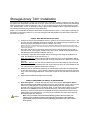
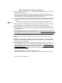
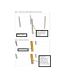
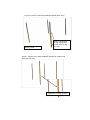
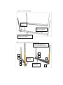
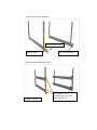
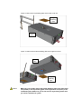
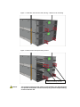
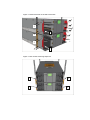
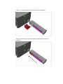
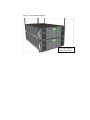
T40+ / Pass-Thru Installation Manual
P/N. 433831 rev.02
February 11, 2008
(kl 16:33)
StorageLibrary T40+ Installation
The purpose of this manual is to help you mount the T40+ / Pass-Thru system correctly into a rack, using
the special rack assemblies included with the unit(s). Follow the same mounting instructions and drawings
when increasing the number of units from 2 to 3, or 3 to 4, and so on.The correct vertical distance in the
rack, between pairs of units, is obtained by using a special rack installation stencil. This stencil allows the
rail mounting screws to only pass thru its punched holes.
Steps 1 to 4 are identical for both the stand-alone and the Pass-Thru option. For the steps explaining the
preparation of the unit(s) (steps 4-14), the text description will differ between the stand-alone option and
the Pass-Thru option.
STEP A: RAIL MOUNTING INTO A RACK
1) Position the special rack installation stencil in 4 places on the rack as shown in figs. 1 & 3.
The two rear rack installation stencils are optional. The stencils must be positioned on the
rack at the same vertical distance from the bottom of the rack.
(NOTE: The holes in a standard rack are NOT evenly distributed. Make sure that the holes in the stencil fully
match the hole-set, see fig. 2. Also make sure that the stencil is placed with the single hole downwards, and the
double hole upwards).
The holes and the text on the stencil ensure the correct vertical position for the rails of
one pair of units. If the system contains more than 2 units, repeat the stencil attachment
with the appropriate number of stencils, see fig. 4.
2) If necessary, adjust the Left and Right rail set according to the length of the Rack to be
used. See illustration of the rail set in fig. 5.
Rack size ≤ 800 mm: Always use the hole-set close to the rear of the adjustable / sliding
part of the rail assembly. The second hole-set to be used should be 100mm from the rear
hole-set.
Rack size > 800 mm: Use the hole-set closest to the rear of the stationary part of the rail
assembly. The distance between this hole-set and the next one to be used should be 100
mm. This will ensure optimum rail stiffness. See fig. 5.
3) Mount the rails on the Rack by attaching the rails with the screws thru the marked holes
on the stencil (see figs. 6, 7 & 8). NOTE: Follow the numbered screw-mounting sequence
in fig. 6 and use the eight M6x12mm countersink screws for this operation (for each set of
rails).
4) Repeat this Rail Mounting Sequence for all units.
STEP B: PREPARING THE UNIT(S) TO BE MOUNTED:
5) Pass-Thru Option: (NOTE: Skip this step if you are using the stand-alone option.)
Remove the appropriate blanking plates on the two units as shown in Figs. 9 and 10. The
holes are normally blinded, and by removing the blanking plate the unit will have a
physical hole in the top plate or the bottom plate, or both top & bottom plates. If the unit is
the lower-most (master) in the new combined structure, only the top plate is removed
(see fig. 9). If the unit is the upper-most (slave) in the new combined structure, only the
bottom plate is removed (see fig. 10). If the unit is in-between two other units, both top
and bottom plates are removed.
Caution
Make sure you do NOT remove the bottom blanking plate of the lower-most unit
(master) or the top blanking plate of the upper-most unit (slave) of the combined
system. Make sure you do not remove any blanking plates when you install a standalone system.
STEP C: MOUNTING THE UNIT(S) INTO THE RACK
6) Slide the unit(s) onto the rails (fig. 11), leaving a space of approximately 100mm for later
ear rack mounting (step 11).
7) Connect the power cable(s) to the unit(s). If using the redundant power supply option
connect both power inlets on the unit(s). Otherwise connect one of the power outlets on
the unit(s). Switch on the corresponding power switch on the unit(s).
8) The library detects that the transport locking screws are present. Follow the instructions
on the front panel display to remove all the magazines and obtain access to the locking
screws.
Caution
Be careful not to drop any of the transport locking screws inside the unit.
9) Remove the four transport locking screws on each unit as shown in fig. 12. If necessary,
see StorageLibrary T40 Installation and User Guide for a detailed description.
10) Mount the Ears on the sides of each unit. Use the eight M3x4mm countersink screws
included with each unit. See fig. 13 and StorageLibrary T40 Installation and User Guide
for further details.
11) Slide the unit(s) fully into the rack and fasten them by mounting the ears to the rack using
the two M6x12mm pan-head screws per unit (see fig. 14 ). NOTE: mount the screw on the
left side before the right side in order to give the correct sideways orientation of the unit.
12) Connect the unit’s Ethernet cable.
13) Connect the Drive cables according to the StorageLibrary T40 Installation and User
Guide.
14) Follow the Setup Wizard in the display for setting up the system. You may re-configure
the library at a later stage if necessary. Refer to the StorageLibrary T40 Installation and
User Guide for more information.
15) Pass-Thru Option: Put the Pass-Thru box into the Pass-Thru magazine (see figs. 15, 16
& 17). Exchange the original T40 LOWER RIGHT MAGAZINE with the PASS-THRU
MAGAZINE (with the Pass-Thru box inserted) and slide it into the LOWER UNIT’S right
lower magazine opening. Re-insert the three other magazines. Re-insert all the original
magazines on the upper unit. The system will now run the inventory sequence and
perform calibration of the unit(s).
Stand-alone Option: Re-insert all four magazines as-is.
The system will now run the inventory sequence and perform calibration of the unit(s).
The system is now ready for use.
Figure 1. Position of the Rack Installation Stencil (Front View).
FRONT VIEW
NOTE: Single hole
facing downwards,
double hole facing
upwards
Figure 2. Matching the Hole-set.
a) CORRECT
b) INCORRECT:
The stencil is
positioned one step
too high, and the
hole pattern on the
stencil and the rail
does not fully match.
Figure 3. Position of the Rack Installation Stencil (Rear View).
REAR VIEW
NOTE: Single hole
facing downwards,
double hole facing
upwards
Figure 4. Aligning of the Rack Installation Stencils for systems with
more than two units.
Align holes, overlap stencils
Figure 5. The Rail Assemblies.
100mm
distance
Stationary part of
the rail assembly
Adjustable / Sliding part
of the rail assembly
Figure 6. Screw Mounting Sequence (Front View).
Follow the numbered
screw mounting sequence.
3
3
4
4
1
2
Left Rail
Assembly
1
Right Rail
Assembly
2
Figure 7. Rear View of the Rack.
Right Rail Assembly
REAR VIEW
Left Rail Assembly
Figure 8. Rack-Ear Mounting Holes.
FRONT VIEW
These holes are for
mounting the ears of the
unit(s) to the rack
Figure 9. Remove the top blanking plate of the lower-most unit.
top
blanking
plate
master
unit
Figure 10. Remove the bottom blanking plate of the upper-most unit.
slave
unit
bottom
blanking
plate
Caution
Make sure you do NOT remove the bottom blanking plate of the lower-most
unit (master) or the top blanking plate of the upper-most unit (slave) of the
combined system. Make sure you do not remove any blanking plates when
you install a stand-alone system.
Figure 11. Slide the units onto the rails, leaving ~100mm for ear mounting.
Figure 12. Remove the transport locking screws.
transport locking screws
Caution
The transport locking screws must be removed before the StorageLibrary
can operate normally. Be careful not to drop any of the transport locking
screws inside the unit.
Figure 13. Mount the ears on the side of the units.
2
2
2
1
2
1
2
2
1
2
2
1
Figure 14. Ear screws mounting sequence.
1
1
2
2
Figure 15. Install the Pass-Thru box in the Pass-Thru magazine.
Figure 16. Exchange the right lower-most magazine with the Pass-Thru
magazine.
Figure 17. The Complete System.
Two T40+ units in
a Pass-Thru Mode.