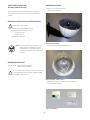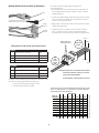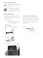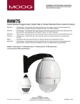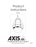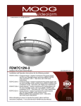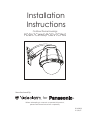
1
Installation
Instructions
Outdoor Dome Housings
PODV7CWNS/PODV7CPNS
Manufactured By:
for
®
Before attempting to connect or operate this product,
please read these instructions completely.
81-IN3090
01/18/07
IMPORTANT SAFEGUARDS
1. Read Instructions - All the safety and operating instructions
should be read before the unit is operated.
2. Retain Instructions - The safety and operating instructions
should be retained for future reference.
3. Heed Warnings - All warnings on the unit and in the operating
instructions should be adhered to.
4. Follow Instructions - All operating and user instructions should
be followed.
5. Electrical Connections - Only a qualified electrician should make
electrical connections.
6. Attachments - Do not use attachments not recommended by the
product manufacturer as they may cause hazards.
7. Cable Runs - All cable runs must be within permissible
distance.
8. Mounting - This unit must be properly and securely mounted to
a supporting structure capable of sustaining the weight of the
unit. Accordingly:
a. The installation should be made by a qualified service person,
and should conform to all local codes.
b. Care should be exercised to select suitable hardware to
install the unit, taking into account both the composition of
the mounting surface and the weight of the unit. Be sure to
periodically examine the unit and the supporting structure to
make sure that the integrity of the installation is intact. Failure
to comply with the foregoing could result in the unit separating
from the support structure and falling, with resultant damages
or injury to anyone or anything struck by the falling unit.
SAFETY PRECAUTIONS
!
Caution
Risk of
Electric Shock!
CAUTION: INSTALLATION BY
QUALIFIED PERSONNEL ONLY
The lightning flash with an arrowhead symbol,
within an equilateral triangle, is intended
to alert the user to the presence of noninsulated "dangerous voltage" within the
product's enclosure that may be of sufficient
magnitude to constitute a risk of electric shock
to persons.
!
The exclamation point within an equilateral
triangle is intended to alert the user to presence
of important operating and maintenance
(servicing) instructions in the literature
accompanying the appliance.
UNPACKING
Unpack carefully. Electronic components can be damaged
if improperly handled or dropped. If an item appears to have
been damaged in shipment, replace it properly in its carton
and notify the shipper.
Be sure to save:
1. The shipping carton and packaging material. They are the
safest material in which to make future shipments of the
equipment.
2. These Installation and Operating Instructions.
SERVICE
For service on Panasonic/Videolarm equipment contact:
Panasonic Technical Center
54 West Gude Dr.
Rockville MD 20850-1150
Phone: 301-762-5125
Fax: 301-251-0347
PANASONIC TECHNICAL SUPPORT
1-800-528-6747
9:00 AM - 5:00 PM EASTERN TIME
--
PODV7CWNS/PODV7CPNS
IP Ready Network Housing
ASSEMBLING THE UNIT:
1. Remove content from all boxes.
Contents should include:
IP Ready Network Housing with 24Vac input, wall mount
or pendant mounting, heater & blowers, WV-NS202 and
camera.
ELECTRICAL SPECIFICATIONS (OUTDOOR ONLY):
!
Power 24Vac, Class 2 Only
Total Power: 52 watts (camera not included)
Accessories (Heater/Blower): 52 watts
Heater:50 watts
Blower: 2 watt
Camera Power: 26 watts
Main Housing Assembly
Either with wall mount or pendant bracket
NOTE: This unit is designed for operation in an
upright position. Installing the housing
upside down may cause damage to
the internal equipment, and will void the
warranty.
GENERAL INSTRUCTIONS:
Tools Required: .100" Flat Head Screwdriver
Phillips Head Screwdriver
!
Be sure the bracket is properly and securely mounted
to a supporting structure capable of rigidly holding
the weight of the entire unit.
Dome Assembly - Clear or Tinted
Do not remove the protective film until the product is
assembled and installed.
3 Packet Assemblies
--
INSTALLATION of the WV-NV202 Camera
in the PODV7 Housing
1. Install the quick release plate on top of the spacers already
installed in the housing. Note the orientation of the bracket.
The securing tab must be facing the front of the housing.
Secure the quick release plate into the housing using the (4)
#8 bolts and star washers provided in the packet assembly.
2. Attach the Camera
to the quick release
plate. Attach safety
lanyard to the back
of the camera.
Position the camera
as shown below on
the quick release
plate and twist
clockwise.
Twist camera to secure
(Please see Pansonic Operation Manual for additonal details.)
Securing Tab
Front
3. Complete wiring connections. Connect the RJ45 network
cable to into the network input. Complete power
connections.
4. Finish camera installation by securing the safety
locking tab.
-+
Power Port
--
WIRING INSTRUCTIONS (OUTSIDE OF HOUSING)
If you wish to provide a single power transformer it is
recommended that:
1. Be certain that you know the total power consumption of
the housing Heater (25 watts) + Blower (1 watt) + camera
pan/tilt (25 watts).
RJ45
2. Check the supplied wiring chart (see below) to be sure that
you have the proper gauge wire for the distance that you
intend to run your power wires.
BNC
(Large)
Power
3. Bring power to the 3 and 4 position of the power connector
(yellow and green wire).
(Small)
Alarms
4. Jumper from the 1st position to the 3rd position and from
the 2nd position to the 4th position of the terminal block.
Be careful not to short between the yellow and green wires.
Green
Add 2 jumpers for
single power input
Wires from
Dome
Wiring Color Code Power and Control Inputs
Yellow
POWER
1
Camera Power (24 VAC)
Red
2
Camera Power (24 VAC)
Orange
3
Heater and Blower Power (24 VAC)
Yellow
4
Heater and Blower Power (24 VAC)
Green
AC
24V
Power
Supply
Side
Orange
Red
CONTROL
Alarm 1
Blue
2
Alarm 2
Violet
3
Alarm 3
Gray
4
Common
White
NOTE: The total power consumption for the heater
and blower, PLUS the camera you choose,
need to be added together.
In this example, a 60VA AC24V is required.
(2) 40Va power transformers are provided with all outdoor units.
The unit is set up with (2) individual power inputs:
1. Accessory Power (yellow and green wire)
2. Camera Power (red and orange)
24V AC Wiring Distances
The following are the recommended maximum distances for 24 VAC
with a 10% voltage drop (10% is generally the maximum allowable
voltage drop for AC powered devices).
Wire Gauge
Total vA
consumed
--
5.5
10
20
30
40
50
60
70
80
90
100
110
120
130
140
22
250
120
89
65
44
35
29
25
31
19
17
16
14
13
12
20
400
180
141
90
70
56
47
40
34
31
28
25
23
21
20
18
18
600
300
225
130
112
90
75
64
55
50
45
41
37
34
32
30
16
960
480
358
225
179
143
119
102
85
79
71
65
59
55
51
47
14
12
10
800 1300 571 905 1440
350 525 830
285 452 720
228 362 576
190 301 480
163 258 411
140 215 340
126 201 320
114 181 288
103 164 261
95 150 240
87 139 221
81 129 205
76 120 192
Maximum distance
from transformer to load
imum distance from transformer
to load
1
INSTALLING THE HOUSING ASSEMBLY:
!
Be sure the bracket is properly and securely mounted
to a supporting structure capable of rigidly holding
the weight of the entire unit.
NOTE: This unit is designed for operation in an
upright position. Installing the housing
upside down may cause damage to
the internal equipment, and will void the
warranty.
INSTALLING PENDANT MOUNT
1. This unit includes a 1½" NPT housing for a standard 1½"
NPT pipe. The housing can be used with other brackets
designed with 1½" male pipe threads, such as the WM20G
wall mount bracket.
2. Attach the housing coupling.
NOTE: Pipe threads should be clean and rustfree. Use the Teflon™ tape included with
the housing on the threads.
3. Mount the housing assembly to the mounting bracket
and housing coupling. A safety cable is included with
the housing to temporarily hold it while making wiring
connections. Loop the safety cable over one of the set
screws on the housing coupling and make the appropriate
connections using the (2) screw-down connectors supplied.
4. Undo the safety cable and twist the housing onto the
housing coupling. Secure all (3) setscrews provided on the
housing coupling.
Add thread
sealing tape
Set screws
A small roll of Teflon tape is provided with all pendant units.
Teflon Tape
--
INSTALLING WALL MOUNT
CONNECTING THE TRIM RING ASSEMBLY TO THE
HOUSING TOP:
A wall mount bracket comes standard with this unit, and
a template is included to use as a guide for mounting the
bracKet to a wall.
1. Open the access door on the bottom of the wall mount by
loosening the screw nearest the mounting plate.
1. Choose the desired location for installation and mark
the drill holes using the template. Screw (2) bolts (not
provided) about ¾ of the way into the (2) top holes. Run
approximately 8 of wiring out of the wall.
NOTE: Be sure the hardware and the mounting
surface can support the weight of the
wall mount bracket plus the weight of the
housing and drive unit. The load will be
subjected to vibration from the camera
motor and wind.
2. The wall mount bracket provided with the FDW7 includes
a location for conduit entry. If you wish to install conduit to
the bracket remove the conduit hole plug. Install fitting from
below the wall mount and secure with conduit nut from
inside the bracket.
Remove dome by twisting counterclockwise
until it stops, then pull down
3. Open the access door on the bottom of the wall mount
by loosening the screw nearest the mounting plate.
2. To attach trim ring align pins with keyhole slots and turn
clockwise about ½" (12mm). Secure (3) screw or use (3)
security screws and security tool provided.
CARE AND CLEANING OF DOMES:
All RHW75 and RHP75 units include an optically clear
polycarbonate dome. The dome is an optical device and
should be handled with extreme care. Leave protective film
on dome until product is fully assembled and installed. Even
though the dome is virtually unbreakable, it can be easily
scratched.
Access panel
Clean only with a clean cotton cloth and warm water.
DO NOT use a strong solvent or cleanser!
4. Attach the wires from the wall to the connector provided.
using the wiring color code chart as a guide.
5. Once all wiring connections are made, place the wires
inside the wall mount bracket and close the access door.
Secure with the screw removed earlier.
--
Exploded View for Replacement Parts
17
16
11
10
18
(1)
9
(1)
(2)
6
8
5
7
19
(1)
15
(3)
12
14
13
4
3
2
1
--
Replacement Parts List
Part Number
Description
1
RPRH702
Lower Trim Ring (White)
2
RC7C
Clear Replacement Capsule
RC7T
Tinted Replacement Capsule
3
RPRH726
Spacing Ring
4
RPRH703
Clamping Ring
5
RPFD072
24VAC Heater
6
RPRH707
Connection PCB
7
RPFD060
Camera Bracket
8
RPFD040
Upper Bracket Assembly
9
RPRH709
Housing Top
10
RPFD2612
Housing Top Gasket
11
WM10
Wall Mount Bracket (Black)
12
RPFD080
12VDC Blower (Used on 24VAC Units)
13
RPNET02
24 to 12DC Power Supply
14
RP-FDJV-2000
Power Supply Bracket
15
RPPKPODV
1” spacers (set of 4)
16
SD0160
Pendent Mount Bracket
17
SD0170
Pendent Housing Coupling
18
RPPKE1125
Electrical Connector Packet
19
RPPKH2100
Housing Hardware Packet – Security Screws
--
Mounting Template
R .733
2.132
5.500
1.537
2.981
2.000
3.250
- 10 -