1
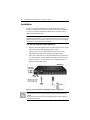
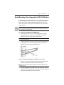
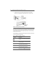
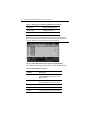
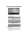
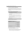
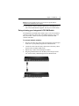
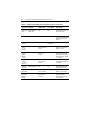
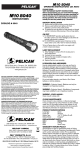
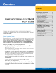
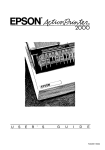
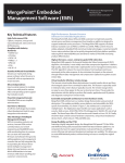
Integrated LCD KVM Switch
For Technical Support:
www.avocent.com/support
Installer/User Guide
Avocent Corporation
4991 Corporate Drive
Huntsville, AL 35805-6201 USA
Tel: +1 256 430 4000
Fax: +1 256 430 4031
Avocent International Ltd.
Avocent House, Shannon Free Zone
Shannon, County Clare, Ireland
Tel: +353 61 715 292
Fax: +353 61 471 871
Avocent Asia Pacific
Singapore Branch Office
100 Tras Street, #15-01
Amara Corporate Tower
Singapore 079027
Tel: +656 227 3773
Fax: +656 223 9155
Avocent Germany
Gottlieb-Daimler-Straße 2-4
D-33803 Steinhagen
Germany
Tel: +49 5204 9134 0
Fax: +49 5204 9134 99
Avocent Canada
20 Mural Street, Unit 5
Richmond Hill, Ontario
L4B 1K3 Canada
Tel: +1 877 992 9239
Fax: +1 877 524 2985
590-698-501A
Integrated LCD
KVM Switch
Installer/User Guide
Avocent, the Avocent logo, The Power of Being There and SwitchView
are registered trademarks of Avocent Corporation or its affliates. All
other marks are the property of their respective owners.
© 2007 Avocent Corporation. All rights reserved. 590-698-501A
Instructions
This symbol is intended to alert the user to the presence of important
operating and maintenance (servicing) instructions in the literature
accompanying the appliance.
Dangerous Voltage
This symbol is intended to alert the user to the presence of uninsulated
dangerous voltage within the product’s enclosure that may be of sufficient
magnitude to constitute a risk of electric shock to persons.
Power On
This symbol indicates the principal on/off switch is in the on position.
Power Off
This symbol indicates the principal on/off switch is in the off position.
Protective Grounding Terminal
This symbol indicates a terminal which must be connected to earth ground
prior to making any other connections to the equipment.
iii
TABLE OF CONTENTS
Table of Contents
Chapter 1: Installation...............................................................1
Introduction.............................................................................................1
Getting Started ........................................................................................1
Installation ..............................................................................................2
Rack Mounting Your Integrated LCD KVM Switch................................3
Accessing and using the OSD menus (LCD monitor)......................5
Accessing and using the OSD menus (KVM switch)........................5
Upgrading firmware ........................................................................7
Daisy-chaining your Integrated LCD KVM Switch .........................9
Appendices .............................................................................. 11
Appendix A: Quick Reference Guide ....................................................11
iv
Integrated LCD KVM Switch Installer/User Guide
1
CHAPTER
Installation
1
Introduction
Supporting both USB and PS/2 interfaces, the Integrated LCD KVM
Switch can control up to eight servers. Built-in keyboard, video and
mouse (KVM) peripherals not only save valuable cabinet space, but also
enable direct channel selection via on-screen display (OSD) or keyboard
hotkeys. The Integrated LCD KVM Switch also features the capacity to
daisy-chain up to 16 levels.
Time-out and password protection offer secure access to the Integrated
LCD KVM Switch, while the hot-plug feature allows for uninterrupted
switching and usage.
Getting Started
Before installing your Integrated LCD KVM Switch, refer to the
following list to ensure you have all items that shipped with the
appliance, as well as other items necessary for proper installation.
Supplied with the Integrated LCD KVM Switch
•
Integrated LCD KVM Switch
•
Rack mount kit
•
Eight KVM cables
•
Power supply
•
Daisy-chain cable
•
Upgrade cable
•
Ground terminator
2
Integrated LCD KVM Switch Installer/User Guide
Installation
If you are installing your Integrated LCD KVM Switch to a PS/2
interface, you must turn off all servers before connecting your appliance
to a server for proper installation. USB interfaces do not need to be
turned off before installation.
NOTE: Linux users may experience mouse failure if hot-plugging directly to the
Integrated LCD KVM Switch. If your mouse becomes locked, use the mouse reset
hotkeys (see Appendix A) to reset your mouse, or turn the Linux server off before
connecting it to the Integrated LCD KVM Switch.
To install the Integrated LCD KVM Switch:
1.
Plug one end of the supplied power cord into the back of the switch
and the other end into an appropriate power source.
2.
Connect your servers to an available port on the rear of your
Integrated LCD KVM Switch using the appropriate cable.
3.
Turn on all connected servers. Keyboard and mouse recognition is
now activated and your Integrated LCD KVM Switch is ready for
operation. Figure 1.1 below shows a basic configuration for the
Integrated LCD KVM Switch.
KVM Switch
USB KVM
Connection
PS/2 KVM
Connection
NOTE: PS/2 and USB
interfaces cannot be
used simultaneously.
Power
Server
Figure 1.1: Basic Integrated LCD KVM Switch Server Configuration
CAUTION: To reduce the risk of electric shock or damage to your equipment:
- Plug the power cord into a grounded (earthed) outlet that is easily accessible at
all times.
- Disconnect the power from the unit by unplugging the power cord from either the
electrical outlet or the unit.
Chapter 1: Installation
3
Rack Mounting Your Integrated LCD KVM Switch
Your Integrated LCD KVM Switch may be rack mounted using brackets.
Before installing the switch, stabilize the rack in a permanent location.
Be sure to rack your Integrated LCD KVM Switch in an area of the
cabinet that will allow you to utilize the LCD monitor, keyboard and
mouse funtions.
CAUTION: Rack Loading - Overloading or uneven loading of racks may result in
shelf or rack failure, causing damage to equipment and possible personal injury.
Do not exceed your rack load rating.
To mount the Integrated LCD KVM Switch:
1.
Loosen the four rear screws of each mounting bracket without
completely removing the screws. You will have to extend the
bracket to access two of the screws on the bracket.
NOTE: Mounting brackets are labeled with an “L” for the left-side bracket and an
“R” for the right-side bracket.
2.
Using the M4 screws provided, connect both left and right brackets
to the cabinet frame. After securing the brackets to the cabinet,
tighten the four rear screws loosened in step 1.
Figure 1.2: Installing the Integrated LCD KVM Switch to a Cabinet
3.
Align the rear of the Integrated LCD KVM Switch with attached
brackets and slide the unit into the front of the cabinet.
NOTE: Avocent recommends having two people assist each other while rack
mounting this unit.
4.
Using the Integrated LCD KVM Switch keys, unlock the unit and
pull the rail lock switches located on the side of the unit. Guide the
Integrated LCD KVM Switch into the cabinet.
4
Integrated LCD KVM Switch Installer/User Guide
5.
Using the flat screws provided, attach both the left and right
brackets to the Integrated LCD KVM Switch to secure the unit.
Rail Lock
Switch
Figure 1.3: Utilizing the Rail Lock Switch
NOTE: To attach the long support brackets (for cabinet mounts more than 33
inches long), you must remove the factory installed rear brackets and replace with
the long brackets provided. Adjust the long brackets to fit the cabinet and use two
of the previously removed screws to tighten. Repeat steps 1-5 of the mounting
procedure to secure the unit.
After installation, reference the following table which lists the functions
of the LCD monitor push-buttons.
Table 1.1: Monitor Push-button Functions
Controls
Description
Soft turn your Integrated LCD KVM Switch
on or off.
Auto
Auto-synchronizes and scales down display
to factory presets.
Up
Allows you to scroll up to a function and
change values within that function.
Down
Allows you to scroll down to a function and
change values within that function.
Menu
Accesses the main menu and acts as the
Enter button. Press Menu to apply changes.
Chapter 1: Installation
5
Accessing and using the OSD menus (LCD monitor)
The panel controls listed in the following table allow you to access and
manipulate the OSD functions of your LCD monitor (Input Source,
Auto Tune, Brightness, Contrast, Color, Position, Language, Recall and
Exit). Each LCD monitor OSD function is accessed by pressing the
Menu button twice and moving up or down to your selection. Press
Menu again to select the option you want to change. See Accessing and
using the OSD menus (KVM switch) on page 5 for more OSD options on
the Integrated LCD KVM Switch.
Table 1.2: OSD Functions (LCD Monitor)
OSD Function
Description
Auto Tune
Automatically tunes the video of your LCD monitor.
Brightness
Allows you to adjust the brightness of the LCD monitor.
Contrast
Allows you to vary the contrast of the LCD monitor.
Color
Allows you to change the color on the LCD monitor.
Position
Allows you to adjust the position of either the image on
the LCD monitor or the OSD itself.
Language
Allows you to select from the following languages:
English, German, French, Italian or Spanish.
Recall
Allows you to recall the original factory settings. Select
Yes in the OSD window after opening this function to
restore factory settings.
Exit
Allows you to quit the OSD menu.
Accessing and using the OSD menus (KVM switch)
The OSD menus for your KVM switch allow you to access and edit
your server name, setup functions, autoscan capabilities and firmware
upgrades. Table 1.3 lists basic OSD hotkey sequences.
Table 1.3: Navigating the OSD Menu (KVM Switch)
To do this:
Use this hotkey sequence:
Activate KVM switch OSD
ScrLk + ScrLk + Spacebar
Deactivate KVM switch OSD
ESC (Escape key)
6
Integrated LCD KVM Switch Installer/User Guide
Table 1.3: Navigating the OSD Menu (KVM Switch) (Continued)
To do this:
Use this hotkey sequence:
Change Value
Left/right arrow keys
Select Item
Up/down arrow keys
NOTE: The two consecutive ScrLk keystrokes should be pressed within two
seconds and the following command key(s) should also be pressed within two
seconds. Otherwise, the hotkey sequence will not be validated.
Figure 1.4: Main OSD Window (8-port Integrated LCD KVM Switch)
The following options will be selectable via the Main OSD window.
Table 1.4: Main OSD Menu Functions
Function
Description
Select server
Use up/down arrow key to navigate and
press PgUp/PgDn to scroll page. Press
Enter to select.
Edit server name
Pressing Insert allows you to change a
server name. Enter confirms the change.
Function
Description
Setup
A submenu for various configurations.
Logout
Logs out keyboard and mouse for security.
Chapter 1: Installation
Figure 1.5: Setup Options Window
The following options will be selectable via the Setup OSD window.
Table 1.5: Setup Menu Functions
Function
Description
Auto logout
Specifies time for auto logout (0 to 99 min). Your
password must be configured and enabled for auto
logout to function.
OSD timeout
Specifies duration for OSD menu to remain on screen.
Autoscan period
Specifies time for the autoscan period.
Title bar
Specifies the position of the OSD title bar.
Hotkey
Specifies the hotkey initiation sequence:
ScrLk (default), Caps Lock, ESC, F12 or
Num Lock.
Setup Password
Enter user-selectable password.
Load Default
Loads the default settings.
Upgrade Firmware Upgrades the firmware of the switch.
Upgrading firmware
The Integrated LCD KVM Switch firmware is upgradable via the
firmware upgrade cable (included). Maintaining current firmware
enhances the Integrated LCD KVM Switch’s compatibility with other
devices. Go to www.avocent.com/support for more information on
upgrading your firmware.
7
8
Integrated LCD KVM Switch Installer/User Guide
To upgrade your Integrated LCD KVM Switch:
Prior to beginning the firmware upgrade process, ensure that you have
an RS-232 port (COM port), a mouse and a keyboard directly connected
to the host server. You will also need the upgrade cable, upgrade utility
and upgrade file.
NOTE: When enabling the upgrade mode via the OSD, be sure to connect a
monitor directly to the host server that performs the upgrade.
1.
Turn on the Integrated LCD KVM Switch.
2.
Press the Menu button twice to invoke the OSD menu and press F1
to enter the Setup Page. Navigate to Upgrade Firmware and press
the Enter button.
3.
Select Yes and press the Enter button to enable upgrade mode.
4.
Use the firmware upgrade cable to connect the RS-232 port (COM
port) of the host server to the Daisy Chain In port of the (primary)
Integrated LCD KVM Switch.
5.
Double-click on the SV1000 upgrade utility icon to bring up the
following window.
NOTE: The firmware upgrade process automatically upgrades all Integrated LCD
KVM Switches daisy-chained to your primary switch.
Figure 1.6: Main Upgrade Utility Window
6.
Click Select File to locate the firmware upgrade file.
7.
Click Check Version to see the current firmware version of your
Integrated LCD KVM Switch. If the selected firmware file is a
newer version, click Upgrade to start the upgrade process.
Chapter 1: Installation
9
NOTE: During the upgrade process, do not remove the upgrade cable or
Integrated LCD KVM Switch power adaptor.
8.
An Upgrade complete! message appears above the progress bar
after a successful firmware upgrade. You may now exit the utility.
Daisy-chaining your Integrated LCD KVM Switch
The Integrated LCD KVM Switch features up to 16 levels of attached
switches via the daisy-chain cable. The KVM switch has a 128 server
daisy-chain limit. Contact Avocent to purchase additional KVM
switches and cables.
To cascade multiple switches:
1.
Plug one end of the daisy-chain cable into the Daisy Chain Out port
on the rear of your primary Integrated LCD KVM Switch.
2.
Connect the other end of the daisy-chain cable to the Daisy Chain
In port on the secondary KVM switch.
3.
Repeat steps 1 and 2 for all subsequent switches.
4.
Plug the ground terminator into the Daisy Chain Out port on the
rear of the last daisy-chained Integrated LCD KVM Switch.
Figure 1.7: Basic Daisy-Chain Example
10
Integrated LCD KVM Switch Installer/User Guide
11
APPENDICES
Appendices
Appendix A: Quick Reference Guide
Table A.1: Integrated LCD KVM Switch Quick Reference Guide
Command Hotkeys
OSD Control
Front-panel
Description
Select
Server
ScrLk + ScrLk + (a)
+ (b) + (y) + (z) ab =
bank no.
xy = channel no.)
Cursor keys to
navigate
Enter to select
Press
corresponding
button yz on
Switch ab for
channel yz on
bank ab
Select the active bank
(switch) and channel
Next Lower
Channel
ScrLk + ScrLk +
(arrow up)
Cursor keys to
navigate
Enter to select
Press
corresponding
button
Select the next lower
connected channel
Next Higher
Channel
ScrLk + ScrLk +
(arrow down)
Enter to select
Press
corresponding
button
Select the next higher
connected channel
Next Lower
Bank
ScrLk + ScrLk +
PgUp
PgUp (w/ OSD
Menu)
Press
corresponding
button
Select the next lower bank
(switch) with multiple daisychained units
Next Higher
Bank
ScrLk + ScrLk +
PgDn
PgDn (w/ OSD
Menu)
Press
corresponding
button
Select the next higher bank
(switch) with multiple daisychained units
Autoscan
Beep Sound
On/Off
ScrLk+ScrLk + B
N/A
N/A
Toggle on/off the beep
sound for switching
confirmation while
autoscanning. The beep
sound can be turned off
during normal switching
Load Factory N/A
Default
Main Menu /
Setup / Load
Default
N/A
Restore the EEPROM
settings to the factory
default
Change
Server
Name
N/A
Enter (Ins) to
select/edit
N/A
Change the server name
[max. length = 8
alphanumeric characters]
Reset /
Initialize
ScrLk + ScrLk +
End
N/A
N/A
Reset the switch/initialize
the daisy-chain setup
12
Integrated LCD KVM Switch Installer/User Guide
Table A.1: Integrated LCD KVM Switch Quick Reference Guide (Continued)
Command Hotkeys
OSD Control
Front-panel
Description
Show OSD
Menu
ScrLk + ScrLk +
(Space Bar)
N/A
N/A
Activate the OSD Menu on
the console screen
Autoscan
ScrLk + ScrLk + S
N/A
N/A
Autoscan through every
connected channel for quick
screen browsing of each
channel
Stop
Autoscan
Any key
N/A
Press any
push-button
Terminate Autoscan activity
Autoscan
Period
[5 ~ 95
seconds]
N/A
Main Menu /
Setup / Autoscan
period
N/A
Specify delay time within a
range of 5 ~ 99 seconds
[default = 10 sec]
Auto Logout
Timeout
Enable/
Disable
0~ 99 min
N/A
Main Menu /
Setup / Auto
Logout
N/A
Specify the time out for auto
logout screen /keyboard/
mouse locked after timeout
period for security (default
= 0 = Disable)
OSD Menu
Timeout
0 ~ 60 ~ 95
seconds
N/A
Main Menu /
Setup / OSD
Timeout
N/A
Specify the timeout for OSD
menu [default = 60 seconds;
0 = disable]
OSD Title
Bar On/Off
ScrLk + ScrLk + T
N/A
N/A
Enable/disable the OSD
Title Bar [default = ON]
OSD Title
Bar Position
Setup
Password
[Disable/
Enable]
Main Menu /
Setup / Title Bar
N/A
Main Menu /
Setup / Setup
Password
Select the OSD title bar
position on your screen
N/A
Enable/disable password
protection [default =
Disable; password length
<= 8 characters]
Integrated LCD KVM Switch
For Technical Support:
www.avocent.com/support
Installer/User Guide
Avocent Corporation
4991 Corporate Drive
Huntsville, AL 35805-6201 USA
Tel: +1 256 430 4000
Fax: +1 256 430 4031
Avocent International Ltd.
Avocent House, Shannon Free Zone
Shannon, County Clare, Ireland
Tel: +353 61 715 292
Fax: +353 61 471 871
Avocent Asia Pacific
Singapore Branch Office
100 Tras Street, #15-01
Amara Corporate Tower
Singapore 079027
Tel: +656 227 3773
Fax: +656 223 9155
Avocent Germany
Gottlieb-Daimler-Straße 2-4
D-33803 Steinhagen
Germany
Tel: +49 5204 9134 0
Fax: +49 5204 9134 99
Avocent Canada
20 Mural Street, Unit 5
Richmond Hill, Ontario
L4B 1K3 Canada
Tel: +1 877 992 9239
Fax: +1 877 524 2985
590-698-501A