1
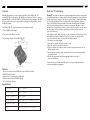
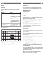
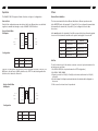
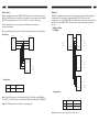
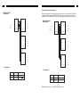
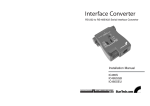
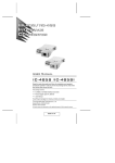
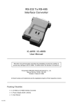
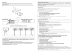
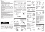
Interface Converter
RS-232 to RS-485/422 Serial Interface Converter
Installation Manual
IC485S
IC485SGB
IC485SEU
1
10
Overview
Radio and TV Interference
Changing line signals is no longer a problem. StarTech.com’s IC485S / GB / EU
converts RS-232 serial interfaces to RS-485/422 serial interfaces. This 2 in 1 converter
converts RS232C to either the RS 485 or RS 422 interface. Other features include DCE/
DTE selectable modes, point to point multidrop configuration and the ability to monitor
RS 485/422 signals.
Warning!!! This equipment generates, uses and radiates radio frequency energy and if
not installed and used in accordance with the instruction manual may case interference
to radio and television reception. It has been tested and found to comply with the limits
for a Class A computing device in accordance with the specifications in Subpart J of
Part 15 of FCC Rules, which are designed to provide reasonable protection against
such interference when operated in a commercial environment. Operation of this
equipment in a residential area is likely to cause interference, in which case the user at
his own expense will be required to take whatever measures may be required to
correct the interference.
The IC485S / GB / EU can be powered from the following two ways:
1. DC 9V, 200mA power adapter
2. The pin #9 of the RS-232 connector
The following is a figure of the IC485S / GB / EU:
If this equipment does cause interference to radio or television reception, which can be
determined by turning the equipment off and on, the user is encouraged to try to
correct the interference by one or more of the following measures:
1. Reorient the receiving antenna.
2. Relocate the computer with respect to the receiver.
3. Move the computer away from the receiver.
4. Plug the computer into a different outlet so that the computer and receiver are on
different branch circuits.
5. Ensure that the mounting screws, attachment connector screws and ground wires
are tightly secured.
6. Ensure that good quality, shielded and grounded cables are used for
data communications.
If necessary, the user should consult the dealer or an experienced radio/television
technician for additional suggestions.
Features
• Two in one converter-Converts RS232C to either RS-485 or RS-422
• DCE/DTE mode selectable
• Supports point to point multidrop configuration
• Can be used to monitor RS-485/422 signals
• Full or half duplex operation
Specifications
Data rate
Up to 1MB/sec
Cable length
Up to 4000ft.
RS-232 connector
DB25 Female
RS-485 connector
RJ11 Female or 4 terminal block
Dimensions (mm)
54 x 74 x 19
Power
Self-powered or DC 9V 200mA
9
2
Appendix
Getting Started
Troubleshooting
This section is designed to help you prepare the IC485S / GB / EU for installation.
Please read through this section carefully before attempting to install the converter.
If failure of printing still exists upon the above solutions, please contact your dealer
for help.
Problem
Failure of Data Transmission
Solution
1. Check that the DC9V power adapter
is available.
2. Check that the IC485SEU is plugged
securely to the PC.
3. Check that the 4-wire cable is
connected properly at both ends.
4. Check that the SW1 and SW2 are
properly set.
Check that the data rate and data format
are the same for both devices.
Data Loss or Error
RS-232 DCE/DTE Description
Device's Connector Pin #
DCE DTE DCE DTE
DB9 DB9 DB25 DB25
2
3
3
2
3
2
2
3
8
7
5
7
8
5
5
4
7
4
5
7
Cables
25/25 or
9/25-Pin
Tx
Rx
RTS
CTS
GND
Rx
Tx
CTS
RTS
GND
IC485S/GB/EU
DCE
DTE
DB25
DB25
3
2
2
3
5
4
7
4
5
7
Unpacking the IC485S / GB / EU
This package should contain:
• 1 x interface converter
• 1 x power adapter
Installation
Before installing the IC485S / GB / EU you will need a 4-wire cable. This cable must go
from your location to the place you want to connect to.
1. Decide on one of the 6 possible configurations suitable for your application. Check the
Operation for the correct slide switch settings and phone wires connection, then
connect the IC485S / GB / EU to the PC.
2. Turn on the PCs.
3. Insert the adapter’s plug into the power jack on the right side of the converter.
4. Plug the power adapter into an AC outlet. The unit is not ready for operation.
Switch Function Description
Device Mode Selection
Position 1: DCE means that the IC485S / GB / EU is set to the DCE mode and must be
connected to a DTE device.
Position 2: DTE means that the IC485S / GB / EU is set to the DTE mode and it must be
connected to a DCE device.
Position 3: Monitor means that the IC485S / GB / EU is set to the monitor mode and it is
used to monitor the RS-485 line signals.
Transmitting and Receiving Mode Selection
Position 1: (TxON, RxON) means the IC485S / GB / EU is always in transmitting mode
and in receiving mode (using in Point-to-Point mode).
Note: The DTE mode devices must be connected ti a DCE mode device because the
polarity of the communication signals are different. The shadow area is a connection
example for a DTE device to a DCE device.
Position 2: (TxRTS, RxRTS) means the IC485S / GB / EU is in transmitting mode while
the RTS is at a high level and it is on receiving mode while the RTS signal is at a low
level (using in Multidrop mode).
Position 3: (TxRTS, RxON) means the IC485 / GB / EU is always in receiving mode and
it is in transmitting mode only while the RTS signal is at a high level (using in Multidrop
mode to monitor the RS/485 line signal).
Note: DTE means Data Terminal Equipment. DCE means Data Communication
Equipment. For more detailed information, refer to the Appendix.
3
8
Operation
Others
The IC485S / GB / EU supports 4 kinds of functions in 6 types of configurations.
Terminal Block Definition
Point-to-Point
The four-screw terminal block has different definitions in different operation modes.
Point-to-Point configuration means two devices that locate different places can be linked
together to communicate through a couple of IC485S / GB / EU devices.
In the DCE/DTE mode, the terminal #1 (-V) and #2 (+V) are configured to transmit data,
the transmitter; the terminal #3 (+V) and #4 (-V) are configured to receive data,
the receiver,
A
Point-to-Point/4-Wire
Full Duplex
B
T+
R+
R-
T-
T-
PC1 =>
COM1/
R-
R+
COM2
=> PC2
Pin #1
1
2
3
4
COM1/
T+
IC485S
In the monitor mode, the terminals #1 and #2 are respectively the positive and negative
of receiver #1; the terminal #3 and #4 are the positive and negative of receiver #2.
IC485S
COM2
Configuration
DCE/DTE
Transmitter - V
Transmitter + V
Receiver + V
Receiver - V
Monitor
Receiver #1 - V
Receiver #1 + V
Receiver #2 + V
Receiver #2 - V
Device
SW1
SW2
A
DCE/DTE
TxON, RxON
Self Test
B
DCE/DTE
TxON, RxON
To test the internal circuit of the interface converter, connect a loop-back terminal to the
unit and process as follows:
1. Set SW1 to DCE (if the loop-back terminal is a DTE configuration).
2. Set SW2 to TxON, RxON.
3. Connect one wire from Tx-(#1) to Rx-(#4), and connect another wire from Tx+(#2)
to Rx+(#3).
4. Set the terminal to full duplex and enter data then the data should be displayed on
the screen.
5. If this occurs, the internal circuit is operational.
If the PC1 is a DTE device, then the Device A SW1 should be set to DCE. If the PC1 is a
DCE device, the the Device A SW1 should be set to DTE. The switch setting method for
the Device be is identical to Device A’s.
Point-to-Point/2-Wire
Half Duplex
A
B
T+
R+
R-
T-
T-
PC1 =>
COM1/
R+
COM2
IC485S
R-
=> PC2
T+
IC485S
Configuration
Device
SW1
SW2
A
DCE/DTE
TxRTS, RxRTS
B
DCE/DTE
TxRTS, RxRTS
COM1/
COM2
7
4
Monitor Mode
Multidrop
Monitor configuration means an IC485S / GB / EU device can be wired to the lines of
RS-232 or RS-422 devices to monitor the line signals. In this configuration the IC485S /
GB / EU will change the function of the T+ and T- to R’+ and R’- respectively.
Multidrop configuration means that more than two devices can be linked all together to
communicate to one another through many IC485S / GB / EU devices. In this
configuration, one of the IC485S / GB / EU devices will be connected to a master device
and the rest of the IC485S / GB / EU devices will be connected to many other slave
devices.
Before operating, the user must complete the installation according to the
procedure mentioned.
Once the installation has been done, the device should operate as the setting function.
Monitoring
Multidrop/4-Wire
Full Duplex
A
Device 2
Device 1
T+
R+
T-
R-
COM1/
T-
R+
COM2
T+
T+
R+
R-
T-
T-
PC1 =>
R-
B1
R-
R+
=> PC2
COM1/
T+
IC485S
IC485S
COM2
B2
A
R+
R-
T+ (R'+)
T- (R'-)
RR+
IC485S
=> PC3
T-
=> PC
COM1/
T+
IC485S
COM1/
COM2
COM2
B3
R+
Configuration
RT-
Device
SW1
SW2
A
MONI
TxRTS, RxON
T+
IC485S
Configuration
Note: R+ and R- signals are converted and linked to the RS-232 port and DB25 pin 3.
R’+ and R’- (T+ and T-) signals are converted and linked to the RS-232 port DB25 pin 2.
Note: The RTS must be at the low level in monitoring mode.
Device
SW1
SW2
A
DCE/DTE
TxON, RxON
B
DCE/DTE
TxRTS, RxON
Note: Bn means any one of the B1, B2, B3 and so on.
=> PC4
COM1/
COM2
5
6
Simplex/Transmit, Receive Only
Multidrop/2-Wire
Half Duplex
A
COM1/
COM2
B1
T+
R+
R-
T-
T-
PC1 =>
Simplex configuration means that more than two devices can be linked all together to
communicate through many IC485S / GB / EU devices. Its configuration is like the
Multidrop’s, but the master device can talk only and the slave devices can listen only.
R-
R+
=> PC2
COM1/
T+
IC485S
IC485S
A
Simplex/Transmit,
Receive Only
COM1/
COM2
T+
R+
R-
T-
T-
PC1 =>
COM2
B1
R-
R+
=> PC2
COM1/
T+
IC485S
IC485S
COM2
B2
B2
R+
R-
R+
=> PC3
T-
R-
COM1/
T+
IC485S
=> PC3
T-
COM2
COM1/
T+
IC485S
COM2
B3
B3
R+
RT-
T+
IC485S
R+
=> PC4
R-
COM1/
T-
COM2
T+
IC485S
Configuration
Configuration
Device
SW1
SW2
A
DCE/DTE
TxRTS, RxRTS
Device
SW1
SW2
B
DCE/DTE
TxRTS, RxRTS
A
DCE/DTE
TxON, RxON
B
DCE/DTE
TxON, RxON
Note: Bn means any one of the B1, B2, B3 and so on.
=> PC4
COM1/
COM2