1
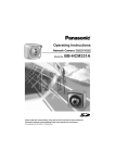
Operating Instructions
BL-C1A
Network Camera
Model No.
BL-C20A
BL-C1A
BL-C20A
Indoor Use Only
Wired Type
Wireless/Wired Type
Please read this manual before using, and save this manual for future reference.
Panasonic Network Camera Website: http://www.panasonic.com/netcam
for customers in the USA or Puerto Rico
Operating Instructions
Main Features
[For BL-C20A] Wireless Communication
This Network Camera is compatible with a wireless system based on IEEE
802.11b/g. Wireless installation is playing an ever increasing role in flexible
communication. The use of encryption ensures security on this kind of network.
Communication via Ethernet cable is also available.
Digital zoom feature*1
This camera has a 10× digital zoom feature. This feature allows you to increase or
decrease the size of objects on the Single Camera screen, the Multi Camera
screen, and the Buffered Image screen. This makes it easy to view distant objects.*2
A mouse wheel operation or clicking the right mouse button increase or decrease
the size of the object.
Color Night View Mode
The color night view mode provides better image quality and low light performance
(4 lx*3).
Multi-Camera Support
The Multi-Camera page displays the moving images from up to 4 cameras. This
camera allows you to switch between 3 sets of 4 cameras. Additionally, static
images from a maximum of 12 cameras can be displayed on a single page.
DynamicDNS Service Support
DynamicDNS service allows you to access the camera over the Internet with a
domain name of your choice (e.g. bob.viewnetcam.com) instead of a global IP
address.
Multi-Language Display
The Top page, Single Camera and Multi-Camera page can be displayed in English,
French, German, Italian, Spanish, Russian, Simplified Chinese, Korean or
Japanese. The Setup, Maintenance and Support pages are displayed only in
English, Japanese, French or Simplified Chinese.
Motion Detection feature
The Camera has a Motion Detection feature that detects movement, such as
people, based on the preset threshold and sensitivity of the Camera. You can buffer
the camera images, transfer images to an FTP server or send E-mails using the
Motion Detection function as a trigger.
*1
*2
*3
This feature is not available when viewing on a cell phone.
As the magnification increases, the image quality decreases.
The brightness about 1 m (3 feet 3 inches) away under auxiliary fluorescent light. When the
object darkens, color night view mode is automatically enabled. The frame rate and the image
quality decrease in color night view mode. Also, images of moving people or animals may be
blurred.
2
Operating Instructions
Documentation
This manual is for both BL-C1A (Wired Type) and BL-C20A (Wireless/Wired
Type). Available features and operations are different in part depending on
the model. Read this manual carefully and use the Network Camera properly.
(The model no. is indicated on the upper left of the front of the main unit.) The
illustrations and images used in this manual are of BL-C20A.
Trademarks
•
•
•
•
•
Adobe, Acrobat and Reader are either registered trademarks or trademarks of
Adobe Systems Incorporated in the United States and/or other countries.
Microsoft, Windows, Hotmail and ActiveX are either registered trademarks or
trademarks of Microsoft Corporation in the United States and/or other
countries.
Screen shots reprinted with permission from Microsoft Corporation.
All other trademarks identified herein are the property of their respective
owners.
This software is based in part on the work of the Independent JPEG Group.
Abbreviations
•
•
•
UPnP is the abbreviation for "Universal Plug and Play".
"Network Camera" is called "Camera" in this manual.
"Setup CD-ROM" is called "CD-ROM" in this manual.
[For assistance, please call: 1-800-272-7033]
3
Operating Instructions
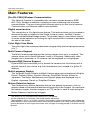
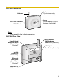
Camera Feature Locations
BL-C1A Front View
Indicator
The indicator color shows camera status.
(See page 96)
Lens (Focus: 0.3 m [about 11 13/16 inches]—
Unlimited)
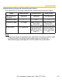
Indicator Display*1
Not on LAN
Orange blinking
Orange
Power
on
Orange blinking
Green blinking
Green
On LAN
Orange
Green
Normal Operation*2
Green blinking
Setting
Automatic
Setup
Finished setting
Green
Green blinking
Orange blinking
Using
Getting IP address*3
DHCP
Green
Got IP address
Updating Firmware
Orange blinking
Orange blinking
Turning off (about 5 seconds)
FACTORY DEFAULT RESET
The status when turned on
button pressed
(The camera is reset to factory default status after 1 minute.)
Orange blinking (About a 2-second interval)
UPnPTM Failure
Internal Failure
Red blinking*4
*1 The information below varies depending on the indicator settings (see page 96).
*2 The indicator turns orange if the camera is not connected to the LAN.
*3 The indicator blinks orange if the camera is not connected to the LAN.
*4 See page 4 of the Troubleshooting on the CD-ROM.
4
Operating Instructions
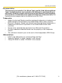
BL-C1A Rear View
Stand/Tripod
Mounting Hole
(See Getting
Started.)
Serial number
MAC Address
(See Getting
Started.)
DC IN jack
(See Getting Started.)
FACTORY DEFAULT
RESET Button
Ethernet
(LAN) port
(See Getting
Started.)
Hook for AC
adaptor cord
[For assistance, please call: 1-800-272-7033]
5
Operating Instructions
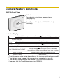
BL-C20A Front View
Antenna
FACTORY DEFAULT
RESET Button
Indicator
The indicator color
shows camera status.
Lens
(0.3 m [about 11 13/16
inches]—Unlimited)
Note
See page 4 for the indicator operations.
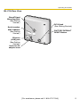
BL-C20A Rear View
Stand/Tripod
Mounting Hole
(See Getting
Started.)
Serial number
MAC Address
(See Getting Started.)
DC IN jack
(See Getting Started.)
Switch
(WIRED or
WIRELESS)
Ethernet
(LAN) port
(See Getting
Started.)
Hook for AC
adaptor cord
6
Operating Instructions
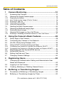
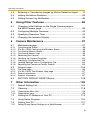
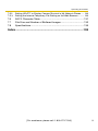
Table of Contents
1
1.1
Camera Monitoring......................................................10
Accessing the Camera ................................................................. 10
1.2
Viewing the Single Camera page................................................. 12
1.2.1
1.2.2
1.2.3
1.2.4
1.2.5
Displaying the Banner ............................................................................. 16
Auto Centering the Image (Click to Center)............................................. 16
Zooming In and Out................................................................................. 17
Capturing a Still Image ............................................................................ 18
Using the Operation Bar .......................................................................... 19
1.3
Viewing the Multi-Camera page ................................................... 20
1.4
Viewing the Buffered Image page ................................................ 22
1.4.1
Deleting Buffered Images ........................................................................ 24
1.5
Viewing Still Images on Your Cell Phone ..................................... 25
1.5.1
Enabling or Disabling the Buffer/Transfer on Your Cell Phone................. 27
2
Using the Camera's Basic Features ..........................28
2.1
Setup Page of the Camera........................................................... 28
2.2
Connecting the Camera to Your Network..................................... 31
2.3
[For BL-C20A] Using Wireless LAN ............................................. 36
2.4
Using UPnP™ (Universal Plug and Play) .................................... 39
2.4.1
2.4.2
Connecting the Camera to a Router that Supports UPnP™ ................... 40
Connecting the Camera to a Router that does not Support UPnP™ ...... 41
2.5
Registering with the DynamicDNS service .................................. 42
2.5.1
DynamicDNS Service.............................................................................. 46
2.6
Setting the Date and Time ........................................................... 48
2.7
Changing Camera Settings .......................................................... 50
3
Registering Users........................................................52
3.1
Changing the Authentication Setting and Administrator User
Name and Password .................................................................... 52
3.2
Logging in to the Camera............................................................. 56
3.3
Creating, Modifying or Deleting General Users............................ 57
4
Buffering or Transferring Images...............................59
4.1
Procedures of Buffering or Transferring Images .......................... 59
4.2
Buffering or Transferring Images by Timer ................................... 60
[For assistance, please call: 1-800-272-7033]
7
Operating Instructions
4.3
Buffering or Transferring Images by Motion Detection Signal ...... 70
4.4
Setting the Motion Detection........................................................ 83
4.5
Setting Sensor Log Notification.................................................... 86
5
Using Other Features..................................................89
5.1
Changing Initial Settings on the Single Camera page or
the Multi-Camera page ................................................................ 89
5.2
Configuring Multiple Cameras...................................................... 92
5.3
Specifying Operation Time........................................................... 94
5.4
Changing the Indicator Display .................................................... 96
6
Camera Maintenance ..................................................97
6.1
Maintenance page ....................................................................... 97
6.1.1
6.1.2
6.1.3
6.1.4
6.1.5
6.1.6
6.1.7
6.1.8
6.1.9
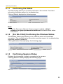
Confirming the Status .............................................................................. 98
[For BL-C20A] Confirming the Wireless Status ....................................... 98
Confirming Session Status ...................................................................... 98
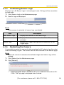
Confirming Sensor Logs .......................................................................... 99
Restarting the Camera ............................................................................ 99
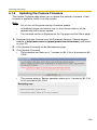
Updating the Camera Firmware............................................................. 100
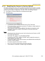
Creating a Configuration File ................................................................. 103
Loading Settings from a Configuration File............................................ 104
Resetting the Camera to Factory Default............................................... 105
6.2
Support page ............................................................................. 106
6.2.1
6.2.2
6.2.3
6.2.4
The Help page ....................................................................................... 106
[For BL-C20A] The Wireless Help page ................................................ 107
Product Information ............................................................................... 107
Support Information ............................................................................... 107
6.3
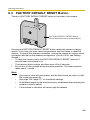
FACTORY DEFAULT RESET Button.......................................... 108
7
7.1
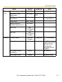
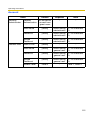
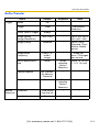
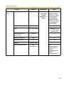
Other Information ......................................................109
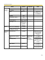
Default Setting List..................................................................... 109
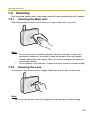
7.2
Cleaning..................................................................................... 118
7.2.1
7.2.2
Cleaning the Main Unit .......................................................................... 118
Cleaning the Lens.................................................................................. 118
7.3
Setting an IP Address on Your PC ............................................. 119
7.4
Using Setup Program................................................................. 120
7.5
Setting Your PC.......................................................................... 127
7.5.1
Setting Proxy Server Settings on a Web Browser ................................ 127
8
Operating Instructions
7.5.2
7.5.3
Setting UPnP™ to Display Camera Shortcut in My Network Places..... 130
Setting the Internet Temporary File Setting on the Web Browser.......... 130
7.6
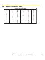
ASCII Character Table ............................................................... 131
7.7
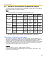
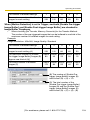
File Size and Number of Buffered Images ................................. 132
7.8
Specifications............................................................................. 135
Index..................................................................................138
[For assistance, please call: 1-800-272-7033]
9
Operating Instructions
1
Camera Monitoring
1.1
Accessing the Camera
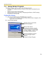
1. Start up the web browser on your PC.
2. Enter "http://IP Address (or URL):Port Number" on the address bar, and
press [Enter] on the keyboard.
•
When the port number is 80 (default), you do not need to include the port
number in the address. See page 33 for details about the port number.
•
If the camera image is not displayed, see page 9 and page 10 of the
Troubleshooting on the CD-ROM.
E.g. http://192.168.0.253:50000
http://
.viewnetcam.com:50000
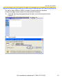
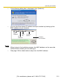
3. The Enter Network Password window is displayed. Enter the user name and
password that you set previously, and click [OK].
Note
When [Permit access from guest users] is set on the Security: Administrator
page (see page 52), the authentication window will not be displayed.
10
Operating Instructions
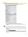
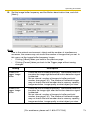
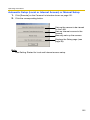
4. Click the following tabs to display each page.
A
B
C
D
E
F
G
Select a language.
Version Number
A To Single Camera page (page 12)
C To Buffered Image page (page 22)
E To Maintenance page (page 97)
G To log in to the camera (page 56)
B To Multi-Camera page (page 20)
D To Setup page (page 28)
F To Support page (page 106)
Note
When users other than an administrator are accessing the camera, the [Setup]
and [Maintenance] tabs are not displayed. Additionally, when [Do not permit
access from guest users] or [Permit access from guest users (mobile only)] is
set on the Security: Administrator page (see page 52), the [Login] tab will not
be displayed.
[For assistance, please call: 1-800-272-7033]
11
Operating Instructions
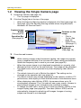
1.2
Viewing the Single Camera page
1. Access the camera (see page 10).
•
The Top page is displayed.
2. Click the [Single] tab at the top of the page.
•
•
When the Security Warning window is displayed, click [Yes] (see page 14).
See page 15 for the Security Warning window when using Microsoft®
Windows® XP Service Pack 2.
Capture Image
Button
(See page 18)
Operation Bar
(See page 19)
Features on the
image
•
Click to
Center (See
page 16)
•
Digital Zoom
(See page 17)
The banner is
displayed.
(See page 16)
3. Close the web browser.
Note
•
•
•
•
•
•
•
While viewing images under fluorescent lighting, the image may appear
noisy or experience flicker if the incorrect AC power setting was selected.
Select the frequency that is used in your area (see page 50).
When the camera image is not displayed immediately or correctly, click
[Refresh] at the tool bar on the web browser. The image will be refreshed.
The digital zoom can be operated only when displaying video (Motion
JPEG).
The refresh interval is set to [Motion] by default. The setting can be
changed on the operation bar (see page 19).
The refresh interval may change depending on the network condition, PC
performance, what object you view and the number of simultaneous users.
When displaying video (Motion JPEG), the camera allows up to 20
simultaneous accesses. The 21st user will see a gray screen. (Access to
play buffered images is also included in the maximum number.)
To reduce the data traffic, set up [Limit Continuous Motion JPEG] on the
Image Display page (see page 89). The video (Motion JPEG) can be
automatically changed to refreshing still images. Images of moving
subject are blurred or not displayed.
12
Operating Instructions
•
•
•
•
•
When the camera transmits a dark scene, the camera image may become
white, or horizontal lines may be displayed on the screen. This is one of the
characteristics of a CMOS sensor. This is not a malfunction.
To display the Single Camera page directly, add it to the [Favorites] on the
web browser.
To view dark images, select [Enable] (default) at Color Night View on the
Camera Setup page. The image will be brighter, but the refresh interval may
increase and image quality may decrease in a dark place. (See page 50)
[For BL-C20A] The video (Motion JPEG) may stop because the wireless
communication may be disconnected depending on the environment.
Click [Refresh] on the web browser when the communication is
disconnected.
If ActiveX® Controls (see page 14 or page 15) cannot be installed,
download them from the Panasonic Network Camera support website at
http://panasonic.co.jp/pcc/products/en/netwkcam/
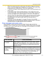
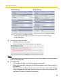
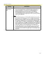
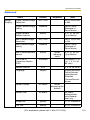
Error messages and screen color
When general or guest users access the Single Camera page outside the
Operation Time, or when over 20 (the maximum number) users access the page
simultaneously, a gray screen and error messages will be displayed on the page.
An error message
is displayed.
Error Message
Cause and Remedy
The operation time
has ended.
When general or guest users access the Single Camera
page outside the Operation Time, a gray screen will be
displayed. Clicking [Refresh] on the web browser displays
an error message. Consult your administrator about the
Operation Time.
The maximum
number of accesses
has been
exceeded.
When [Motion] is selected for the Refresh Interval, up to 20
users can access the camera simultaneously. For the 21st
user, a gray screen and an error message will be displayed
on the Single Camera and Buffered Image pages. Wait for
a moment, and click [Refresh] on the web browser, or
change the value for the Refresh Interval.
[For assistance, please call: 1-800-272-7033]
13
Operating Instructions
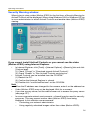
Security Warning window
When trying to view a video (Motion JPEG) for the first time, a Security Warning for
ActiveX Controls will be displayed. When using Windows 2000 or Windows XP, log
in as an administrator to install ActiveX Controls and enable video (Motion JPEG)
viewing.
If you cannot install ActiveX Controls or you cannot see the video
(Motion JPEG) using Internet Explorer
•
In Internet Explorer, click [Tools]→[Internet Options]→[Security] tab and click
[Custom level].
(1) Check "Prompt" in "Download signed ActiveX Controls".
(2) Check "Enable" in "Run ActiveX Controls and plug-ins".
•
ActiveX Controls can be installed from the CD-ROM.
(1) Restart the PC.
(2) Confirm that Internet Explorer is closed.
(3) Double-click "ocx\ActiveXInst.exe" on the CD-ROM.
Note
•
When the IP address was changed for the camera, enter it on the address bar.
•
Video (Motion JPEG) may not be displayed. Wait for a moment.
•
If you use a proxy server, set the web browser not to access the proxy server
(see page 127).
•
In some corporate network environments, a firewall may be used for security
purposes. This may prevent motion video (Motion JPEG) from being
displayed. In this situation we recommend:
– Contacting your network administrator.
– Using regularly refreshed images rather than video (Motion JPEG).
14
Operating Instructions
Security Warning window on Microsoft Windows XP Service Pack 2
To view a video (Motion JPEG), ActiveX Controls must be installed.
Follow the steps shown below to install ActiveX Controls.
1. Click the warning displayed above the tabs, and click [Install ActiveX
Control...].
2. Click [Install].
[For assistance, please call: 1-800-272-7033]
15
Operating Instructions
1.2.1
Displaying the Banner
An image and its linked website can be specified for a banner. To display the
banner, the Banner Display settings need to be set on the Image Display page (see
page 89). Clicking the banner displays the website of the set URL Link. The Banner
Display is not enabled as the default.
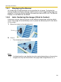
1.2.2
Auto Centering the Image (Click to Center)
Using your mouse, click any portion of the camera image when using the digital
zoom. The image will automatically move to place the selected point in the center
of the screen.
1. Move the cursor to the desired point.
Cursor
2. Click it.
•
The clicked point is centered.
Note
•
•
A clicked position may deviate from the center depending on the position.
Images can only be moved within the page when magnification is ×1.
16
Operating Instructions
1.2.3
Zooming In and Out
This Camera has 10× digital zoom feature that uses ActiveX Controls. The digital
zoom feature can be used while playing video (Motion JPEG) on the Single
Camera, Multi-Camera and Buffered Image pages. The digital zoom feature can be
operated by rotating the mouse wheel or clicking the right mouse button.
Note
•
•
•
•
The Click to Center feature is available while zooming in or out. Images
can only be moved within the page when magnification is ×1.
As the magnification increases, the image quality decreases.
This feature is not available when viewing on a cell phone.
When camera images are buffered and transferred, the camera images
are not zoomed in and out.
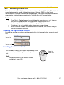
Clicking the right mouse button
Moving the mouse up or down while pressing the right mouse button zooms in and
out.
Zoom in
Zoom out
Rotating the mouse wheel
On a screen, rotating the mouse wheel away from
you zooms in, and rotating it towards you zooms
out.
Zoom in
Zoom out
Note
The performance of the mouse varies
according to your OS.
[For assistance, please call: 1-800-272-7033]
17
Operating Instructions
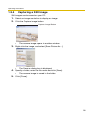
1.2.4
Capturing a Still Image
Still images can be saved on your PC.
1. Select an image resolution to display an image.
2. Click the Capture image button.
Capture Image Button
•
The camera image opens in another window.
3. Right-click the image, and select [Save Picture As...].
•
The Save as dialog box is displayed.
4. Specify a folder, enter the file name and click [Save].
•
The camera image is saved in the folder.
5. Click [Close].
18
Operating Instructions
1.2.5
Using the Operation Bar
Brightness: Adjusts image brightness in nine steps including
[STD] (Standard). Clicking [-] or [+] darkens or
brightens the image respectively.
Refresh
Interval:
Sets a refresh interval. (Motion—60-second
interval)
Resolution: Selects [640 × 480] or [320 × 240] (default) pixels.
Image
Quality:
Selects the image quality.
•
[Favor Clarity] optimizes the image for good
clarity.
•
[Standard] keeps the standard quality. (default)
•
[Favor Motion] optimizes the image for motion
display.
[For assistance, please call: 1-800-272-7033]
19
Operating Instructions
1.3
Viewing the Multi-Camera page
To view multiple cameras on the Multi-Camera page, you need to configure each
camera on the Multi-Camera Setup page (see page 92).
1. Access the camera (see page 10).
•
The Top page is displayed.
2. Click the [Multi] tab at the top of the page.
•
The Multi-Camera page can display up to 12 camera images.
Capture Image Button (See page 18)
Switches displayed
cameras. If you select
[All] at the View Type,
video (Motion JPEG)
cannot be displayed.
Selects [320 × 240]
(default) or [160 ×
120] pixels resolution.
Selects the refresh
interval (Motion—60second interval).
The Selfcamera is registered at No. 1. (default)
Clicking the camera
name displays the
Single Camera page
in another window.
3. Close the web browser.
20
Operating Instructions
Note
•
•
•
•
•
•
•
•
•
The digital zoom feature and the Click to Center feature can be used for
video (Motion JPEG) only.
When selecting [All] for the View Type, all images are displayed in 160 ×
120 pixels resolution.
640 × 480-pixel images cannot be displayed on the Multi-Camera page.
When viewing video (Motion JPEG), we recommend using an Ethernet
switching hub instead of a repeater hub to prevent degradation in video
display.
Due to network congestion or the number of accesses, the refresh interval
may increase.
If the refresh interval is too long, restrict the bandwidth on the Network
page (see page 34). The refresh interval should improve.
To reduce the data traffic, set up [Limit Continuous Motion JPEG] on the
Image Display page (see page 89). The video (Motion JPEG) can be
automatically changed to refreshing still images. Images of moving
subject are blurred or not displayed.
When viewing 4 cameras on the Multi-Camera page, you may need 3 to 4
Mbps bandwidth. If sufficient bandwidth is not available, the refresh
interval may increase.
The Click to Center feature can be used while using the digital zoom.
When an image is not displayed on the Multi-Camera page
•
•
•
Confirm that the global IP address is specified correctly for each camera and
that each camera is connected to the Internet. For Internet access, local IP
addresses (192.168.
.
) cannot be used. (See page 11 of
Troubleshooting on the CD-ROM)
Confirm the settings on the Multi-Camera Setup page (see page 92).
Confirm that the web browser is not accessing a proxy server (see page 127).
When setting [Do not permit access from guest users] or [Permit
access from guest users (mobile only)] on the Security:
Administrator page
•
•
An authentication window is displayed when accessing the camera. Enter the
administrator's or the general user's user name and password.
When you view images from several cameras on the Multi-Camera page, an
authentication window is displayed for each camera that has security settings
enabled. Enter the administrator's or general user's user name and password
registered for each camera.
[For assistance, please call: 1-800-272-7033]
21
Operating Instructions
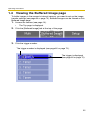
1.4
Viewing the Buffered Image page
To buffer images in the camera's internal memory, you need to set up the image
transfer settings (see page 60 or page 70). Buffered images can be viewed on this
Buffered Image page.
1. Access the camera (see page 10).
•
The Top page is displayed.
2. Click the [Buffered Image] tab at the top of the page.
3. Click the trigger number.
The trigger number is displayed (see page 60 or page 70).
The trigger is displayed
(see page 60 or page 70).
22
Operating Instructions
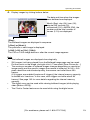
4. Display images by clicking buttons below.
The date and time when the images
were buffered are displayed.
Month (Sep), day (20), hour (02),
minute (58), second (15),
millisecond (120), AM/PM (PM), the
number and the total number of
frames (1/10) are displayed.
[Play]:
The buffered images are displayed in sequence.
[<Prev] or [Next>]:
The previous or next image is displayed.
[<100], [<10] or [10>], [100>]:
The 10th or 100th image before or after the current image appears.
Note
•
The buffered images are displayed chronologically.
•
Still images (not being played) from the Buffered Image page can be saved.
Put the cursor on the image, and right-click it. Then select [Save Picture As...].
•
The maximum number of buffered images changes depending on resolution,
image quality and the specific images the camera is buffering. At 320 × 240
pixels resolution and standard quality, the camera can buffer about 250
frames.
(If 3 triggers are enabled [maximum 5 triggers], the internal memory capacity
is divided into 3 sections. In this case, each trigger can buffer about 80
frames.) See page 132 for more details regarding the internal memory
capacity.
•
The digital zoom can be used while viewing buffered images (while playing
video [Motion JPEG]).
•
The Click to Center feature can be used while using the digital zoom.
[For assistance, please call: 1-800-272-7033]
23
Operating Instructions
1.4.1
Deleting Buffered Images
If you intend to delete images for each transfer method, click [Delete Buffered
Images] on the Trigger page (see page 60 or page 70).
Note
•
If you are buffering images to the internal memory, the following operations
also delete all buffered images.
– Turning off the camera.
– Saving the Date and Time page.
– Restarting, updating firmware or resetting the camera to factory default.
– Changing the Enable/Disable settings on the Image Buffer/Transfer page
(See page 60 or page 70).
24
Operating Instructions
1.5
Viewing Still Images on Your Cell Phone
Still images can be viewed over the Internet from a compatible cell phone.
Enter "http://IP address (or URL):Port Number/mobile" on a cell phone and
press [OK].
•
When the port number is set to 80 (default), it is not required.
E.g. http://
.
(or
•
•
•
.
.
:50000/mobile
.viewnetcam.com:50000/mobile)
Allow access from the Internet to access the camera from cell phones.
When an authentication window is displayed, enter the administrator's or
general user's user name and password.
A still image is displayed. (Video [Motion JPEG] cannot be displayed.)
Pressing 5 will refresh the image.
160 × 120 resolution is displayed on the first access.
Pressing 0 switches the resolution to 320 × 240.
Displays up to 50 Logs in order of time. (Only for an
administrator)
An administrator can
enable or disable the
Image Buffer/Transfer
setting from your cell
phone. (See page 27)
Goes to the control page.
Displays the number of
new logs.
MD: Motion Detection
Displays the date and
time.
Goes to the control page.
[For assistance, please call: 1-800-272-7033]
25
Operating Instructions
Note
•
If the image is not displayed properly, try the following 2 URLs.
1. http:// IP address(or URL):Port Number/MobileH for HTML.
(or
.viewnetcam.com:50000/MobileH)
2. http:// IP address(or URL):Port Number/MobileX for XHTML.
(or
•
•
•
•
.viewnetcam.com:50000/MobileX)
Some cell phones are not compatible with Panasonic Network Cameras.
Some phones may allow viewing only on port 80, and some may not support
password authentication. See the Panasonic Network Camera support
website below for a list of cell phones, and their level of compatibility with the
Panasonic Network Camera.
Some cell phones display images at a decreased size.
If [Permit access from guest users] or [Permit access from guest users (mobile
only)] is selected, users can access cell phone-specific screens via a cell
phone or PC without the need for authentication.
Only administrators can operate the Sensor log and Buffer/Transfer.
Panasonic Network Camera support website:
http://panasonic.co.jp/pcc/products/en/netwkcam/
26
Operating Instructions
1.5.1
Enabling or Disabling the Buffer/Transfer on Your
Cell Phone
1. Access camera images from your cell phone, and log in as an administrator
(see page 25).
2. Select [Buffer/Transfer].
3. Select a trigger number that you want to enable or disable.
Example: Enabling the Buffer/Transfer setting (No.1).
•
Selecting [Control Page] changes to the previous page.
4. Select [Save].
•
•
Selecting [Save] enables or disables the buffer/transfer settings, and all
buffered images will be deleted.
Selecting [Cancel] takes you back to the previous page without saving
changes.
[For assistance, please call: 1-800-272-7033]
27
Operating Instructions
2
Using the Camera's Basic Features
2.1
Setup Page of the Camera
1. Access the camera (see page 10).
•
The Top page is displayed.
Note
•
•
When [Permit access from guest users] is set on the Security:
Administrator page, click the [Login] tab (see page 56) and log in as an
administrator.
When users other than an administrator are accessing the camera, the
[Setup] and [Maintenance] tabs are not displayed.
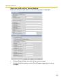
2. Click the [Setup] tab at the top of the page.
* The feature is for only BL-C20A.
(1)
(2)*
(3)
(4)
(5)
(6)
(7)
(8)
(9)
(10)
(11)
(12)
(13)
(14)
(15)
28
Operating Instructions
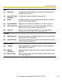
Basic
(1)
Network
Configures network settings to connect the camera to the
network (see page 31).
(2)
[For BL-C20A]
Wireless
Configure a wireless network (see page 36).
(3)
UPnP
Enables automatic port forwarding and creates a shortcut
to the camera (see page 39).
(4)
DynamicDNS
Registers with the DynamicDNS service (see page 42).
(5)
Date and Time
Sets the date and time, automatic time adjustment and
daylight saving time settings (see page 48).
(6)
Camera
Sets camera name, white balance, AC power source
frequency and color night view (see page 50).
Account
(7)
Administrator*1 Sets authentication and administrator security (user name
and password) (see page 52).
(8)
General User*1
Sets general user security (user name and password) and
access levels (see page 57).
Buffer/Transfer
(9)
Trigger
Sets image buffer or transfer by timer or motion detection.
(See page 60 or page 70)
(10)
Motion
Detection
Sets the threshold and sensitivity for motion detection (see
page 83).
(11)
Sensor Log
Sets the information required to send log notifications by email (see page 86).
[For assistance, please call: 1-800-272-7033]
29
Operating Instructions
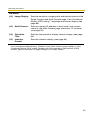
Advanced
(12)
Image Display
Sets the resolution, image quality and refresh interval of the
Single Camera and Multi-Camera page, Limit Continuous
Motion JPEG setting*1, language and banner display (see
page 89).
(13)
Multi-Camera*1
Sets the camera IP address or host name, and camera
name on the Multi-Camera page (maximum 12 cameras)
(see page 92).
(14)
Operation
Time
Sets the time period to display camera images (see page
94).
(15)
Indicator
Control
Sets the indicator display (see page 96).
*1
If you change the [Administrator], [General User], [Multi-Camera] page settings or Limit
Continuous Motion JPEG setting, changes will not be applied to video (Motion JPEG)
viewers. Restart the camera to apply changes to all video viewers.
30
Operating Instructions
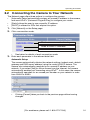
2.2
Connecting the Camera to Your Network
The Network page offers three options to configure the camera.
•
[Automatic Setup] automatically assigns an unused IP address to the camera,
and uses UPnPTM (Universal Plug and Play) to configure your router.
•
[Static] allows the user to use a specific IP address.
•
[DHCP] is offered for ISPs that require this option.
1. Click [Network] on the Setup page.
2. Click a connection mode.
Most common mode of setup.
Uses a static IP address.
Uses ISP DHCP server function.
•
See below for details of each connection mode.
3. Enter each parameter in the relevant data field.
Automatic Setup
The camera automatically obtains the network settings (subnet mask, default
gateway and DNS server address) using the router's DHCP feature. The
camera also automatically searches for an unused IP address on your
network. If you select [Yes] for Allow Access from the Internet, the camera
automatically enables port forwarding using UPnPTM. In this case, the camera
automatically searches for an unused port number on your network in order
from 50000 to 50050.
•
Clicking [Cancel] takes you back to the previous page without saving
changes.
[For assistance, please call: 1-800-272-7033]
31
Operating Instructions
DHCP Setup
•
Static Setup
Clicking [Cancel] takes you back to the previous page without
saving changes.
4. Click [Save] when finished.
•
•
The new settings are saved.
When finished, the following page is displayed.
Note
The current network settings are shown on the Status page in the Maintenance
section (see page 98).
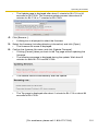
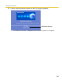
5. Click [Restart].
•
•
•
The camera restarts, and the Top page is displayed.
When the camera is restarted, all buffered images in the internal memory
are deleted.
Checking [Yes] for [Allow Access from the Internet] on [Automatic Setup]
may not display the Top page, because the port number may change. Use
the Setup Program to access the camera.
32
Operating Instructions
Note
If you do not know the camera IP address when setting [Automatic Setup] or
[DHCP Setup], it can be searched for by using the Setup Program (see page
120).
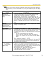
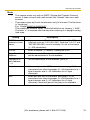
Setting
Allow Access from
the Internet
(Automatic Setup
Only)
Description
•
The Allow Access from the Internet setting automatically
configures the router's Port Forwarding setting (some
routers call it "Address Translation", "Static IP
Masquerade", "Virtual Server" or "Port Mapping"). To
enable Internet access to the camera, check [Yes]. In this
case, the camera automatically searches for an unused
port number on your network in order from 50000 to
50050. To disable Internet access to the camera, check
[No].
Network
•
Configuration from
Setup Program
(Static/DHCP Only)
To prohibit the Setup Program from changing the network
settings, uncheck the box.
Port Number
•
(Static/DHCP Only)
The default port number is 80. When you use multiple
cameras with a router on your network, each camera must
be assigned its own port number (see page 41 "2.4.2
Connecting the Camera to a Router that does not Support
UPnP™").
– Do not set the following port numbers.
FTP: 20 and 21, Telnet: 23, SMTP: 25, DNS: 53,
POP3: 110, HTTPS: 443, ICQ: 4000 and IRC: 6661—
6667.
Enter a number between 1—65535.
Some ISPs do not allow you to use port 80. Ask your ISP
or network administrator about which port numbers are
accessible over the Internet.
•
•
•
IP address
•
Subnet Mask
(Static Only)
•
•
•
If your ISP or network administrator specifies an IP
address and subnet mask, enter them in each data field.
If you use the camera on a LAN, set an IP address with the
same class as your PC (see page 119).
Set 4 numbers (0—255) and 3 periods, such as
"192.168.0.253". Note that "0.0.0.0" and
"255.255.255.255" are not available.
[For assistance, please call: 1-800-272-7033]
33
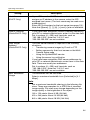
Operating Instructions
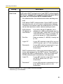
Setting
Host Name
(DHCP Only)
Description
•
•
If your ISP uses the DHCP function, which automatically
assigns an IP address to the camera, enter the ISPassigned host name. (The host name may be used as an
authentication.)
Enter ASCII characters for the host name (see page 131).
Note that [Space], ["], ['], [&], [<] and [>] are not available.
Default Gateway*1
•
(Static/DHCP Only)
•
If you have been assigned a Default Gateway address by
your ISP or network administrator, enter it in this data field.
Set 4 numbers (0—255) and 3 periods, such as
"192.168.0.253". Note that "0.0.0.0" and
"255.255.255.255" are not available.
DNS Server
•
Address*1
(Static/DHCP Only)
The DNS server address is required in the following
situations:
– Transferring camera images by E-mail or FTP
– Setting cameras by their host names on the MultiCamera Setup page
– Using the DynamicDNS service
– Using the sensor log notification
If you have been assigned a DNS server addresses by
your ISP or network administrator, enter them in this data
field. There are usually two addresses.
Set 4 numbers (0—255) and 3 periods, such as
"192.168.0.253". Note that "0.0.0.0" and
"255.255.255.255" are not available.
•
•
Max. Bandwidth
Usage
•
•
The bandwidth can be restricted.
Select a maximum bandwidth from [Unlimited] to [0.1
Mbps].
Note
Set a maximum bandwidth referring to the following file
sizes. These are examples for a JPEG file of standard
image quality. File sizes may change depending on the
image quality or the brightness of the object.
160 × 120 pixels: About 3 KB (24 Kbit)
320 × 240 pixels: About 10 KB (80 Kbit)
640 × 480 pixels: About 18 KB (144 Kbit)
34
Operating Instructions
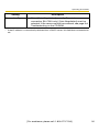
Setting
Connection Type
*1
Description
•
Select [Auto Negotiation] normally. For wireless
connection (BL-C20A only), [Auto Negotiation] must be
selected. If the camera cannot be accessed, see page 9 of
Troubleshooting on the CD-ROM.
If the IP address is automatically obtained from a DHCP server, this field does not need to be
set.
[For assistance, please call: 1-800-272-7033]
35
Operating Instructions
2.3
[For BL-C20A] Using Wireless LAN
Wireless communication is possible by adjusting the settings of the wireless LAN
to those of the wireless router. Take a note of the settings and save them for
reference. For more information about wireless settings, please refer to http://
panasonic.co.jp/pcc/products/en/netwkcam/.
1. Click [Wireless] on the Setup page.
2. Set each parameter for Wireless Configuration.
Setting
SSID
Description
•
Communication •
mode
•
•
*1
The SSID must be set to match the SSID your wireless
router or wireless LAN uses. The SSID is limited to 32
characters (alpha numeric) and is case sensitive.
802.11b: There are a lot of 802.11b-compliant products
and they are inexpensive. They are widely prevalent, so it
is likely that 802.11b will match your existing wireless
devices.
802.11b/g (default): This mode supports both the 802.11b
and 802.11g wireless LAN standards. It is the
communication mode that is easiest to install on your
existing wireless LAN.
802.11g exclusive: This mode communicates using
802.11g only. It does not support the mixed standard mode
of 802.11b/g, so it allows the use of original features of
802.11g.*1
Even if "802.11g exclusive" is in use, the existence of other wireless devices using a 2.4
GHz bandwidth —including 802.11b wireless devices— may make the baud rate on the
802.11g slower.
36
Operating Instructions
3. Set each parameter for Encryption.
Setting
Description
Cipher
•
•
Select to encrypt or not encrypt.
To prevent unauthorized users from reading data, selecting
[WEP] is recommended.
WEPKey
Selection
•
The checked WEPKey is used as the standard WEPKey.
Check the same WEPKey as the one selected for the
router.
WEPKey1—4
•
Select one from [HEX, 10 characters 64 bit], [HEX, 26
characters 128 bit], [HEX, 32 characters 152 bit], [ASCII 5
characters 64 bit], [ASCII 13 characters 128 bit] or [ASCII
16 characters 152 bit].
Selecting [WEP] at Cipher enables you to set WEPKey1—
4. One or all of the four keys can be set. Check the same
key number as set to the wireless router, and set the same
encryption as at the wireless router.
•
<Example>
HEX, 10 characters 64 bit
: 012345abcd
HEX, 26 characters 128 bit
: 0123456789abcdef012
345abcd
HEX, 32 characters 152 bit
: 0123456789abcdef012
3456789abcdef
ASCII 5 characters 64 bit
: 012yz
ASCII 13 characters 128 bit
: 0123456uvwxyz
ASCII 16 characters 152 bit
: 0123456789uvwxyz
[For assistance, please call: 1-800-272-7033]
37
Operating Instructions
Note
•
•
Some wireless devices do not support the WEP 152 bit encryption.
The camera supports only open system authentication. If the wireless
router or access point is set to shared key authentication, set it to auto or
open system.
4. Click [Save] when finished.
•
•
The new settings are saved.
When finished, "Success!" is displayed.
5. Click [Go to Wireless configuration page].
•
The Wireless page is displayed.
6. Set the switch to WIRELESS.
Note
•
•
•
•
•
•
Encryption helps protect data within wireless LAN from third parties.
Enter both the MAC addresses for the camera itself and the camera's
wireless module to enable the MAC address filtering feature on the
wireless router. The wireless module MAC address is one value higher
than the camera MAC address.
It takes about 1 minute for the new settings to become effective.
It is not possible to access the camera simultaneously by both wired and
wireless connection.
To communicate using wireless connection, set up the camera using wired
connection and flip the switch from WIRED to WIRELESS as shown
below.
Even if the camera is set to wired connection, it emits electrical waves for
about 5 minutes after the power has been on. During this time, the router's
wireless indicator is on or blinking. Electrical waves will stop being
transmitted after about 5 minutes.
< Side >
Switch
•
When you switch from WIRED to WIRELESS or vice versa, restart the
camera. Some routers may also need to be restarted after switching.
38
Operating Instructions
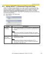
2.4
Using UPnP™ (Universal Plug and Play)
UPnPTM can automatically configure your router to make it accessible from the
Internet. In order to use this feature, your router needs to support UPnPTM, and it
must be enabled. UPnPTM is disabled on most routers by default. See http://
panasonic.co.jp/pcc/products/en/netwkcam/ and your router's manual for
details of how to enable UPnPTM. After UPnPTM is enabled on the router, set [Enable]
for auto port forwarding.
1. Click [UPnP] on the Setup page.
2. Set up UPnP.
Setting
Auto Port
Forwarding
Description
•
If the network setting is [Static] or [DHCP], enabling auto
port forwarding allows you to access the camera from the
Internet.
Note
If the network setting is [Automatic Setup], also enable
[Allow Access from the Internet] on the Network page (see
page 33).
Display Shortcut •
Icon in My
Network Places
Enabling this creates a shortcut to the camera in the My
Network Places folder.
Note
To enable this feature when using Windows XP or
Windows Me, enable the UPnPTM Windows component
beforehand (see page 130).
[For assistance, please call: 1-800-272-7033]
39
Operating Instructions
3. Click [Save] when finished.
•
•
The new settings are saved.
When finished, "Success!" is displayed.
4. Click [Go to UPnP page].
•
2.4.1
The UPnP page is displayed.
Connecting the Camera to a Router that Supports
UPnP™
To allow access from the Internet with a router supporting UPnPTM, follow the
procedures shown in Getting Started.
Note
•
•
On some routers, the UPnPTM feature is disabled by default. Enable your
router's UPnPTM feature following the router manual before you set up the
camera. See the Panasonic Network Camera support website at http://
panasonic.co.jp/pcc/products/en/netwkcam/ for details.
If a maximum idle time is set in PPPoE or PPTP connection with your ISP,
disable it on the router. See the router manual for details.
40
Operating Instructions
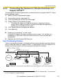
2.4.2
Connecting the Camera to a Router that does not
Support UPnP™
To allow access from the Internet with a router that does not support UPnPTM, follow
the procedures below.
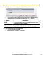
1. Select [Static] on the Network page.
(1) Access the camera (see page 10).
(2) Click the [Setup] tab at the top of the page.
(3) Select [Static] on the Network page.
•
The Static IP Address Configuration page is displayed. Make a
note of the IP address and port number, since they are required to
enable port forwarding on the router.
(4) Click [Save] without changing the settings.
(5) Click [Restart].
2. Enable port forwarding*1 on the router.
Using the IP address and port number noted on step 1-(3), enable port
forwarding on the router. See the router manual for how to enable port
forwarding.
3. Register with the DynamicDNS service.
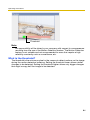
Port Forwarding feature*1
The port forwarding feature is required to allow camera access from the Internet
with a router that does not support UPnPTM. It exchanges a local IP address for a
global one. Each camera must be assigned a unique port number.
Global IP address or URL
Port No.
Port Forwarding feature
vvv.xxx.yyy.zzz:80
vvv.xxx.yyy.zzz:81
vvv.xxx.yyy.zzz:80
vvv.xxx.yyy.zzz:81
192.168.0.253:80
192.168.0.252:81
Internet
192.168.0.254
Router
192.168.0.1
192.168.0.252
192.168.0.253
Port No. 80
Port No. 81
Note
The IP addresses shown above may differ from those offered on your home network.
*1
"Port forwarding" may be called "Address translation", "Static IP Masquerade", "Virtual server"
or "Port mapping" in other products.
[For assistance, please call: 1-800-272-7033]
41
Operating Instructions
2.5
Registering with the DynamicDNS service
DynamicDNS is a service that allows you to assign an easy-to-remember name to
the camera, for example, similar to your favorite web site. It also allows you to easily
access the camera, even when your ISP changes the IP address. Panasonic
Communications recommends that you register with a DynamicDNS to access the
camera from the Internet. See http://www.viewnetcam.com for details about the
Viewnetcam.com service.
1. Click [DynamicDNS] on the Setup page.
•
•
When you select [Disable] or [Viewnetcam.com] (see page 42)
When you select [User-specified DynamicDNS] (see page 44)
When you select [Disable]
2. Click [Save].
•
•
The DynamicDNS service is disabled.
Clicking [Cancel] cancels your settings without saving changes.
When you select [Viewnetcam.com]
2. Click [Next].
•
Clicking [Cancel] cancels your settings without saving changes.
42
Operating Instructions
3. Click [Save].
•
Clicking [Cancel] cancels your settings without saving changes, and the
DynamicDNS window is displayed.
Setting
Description
Personal
(Camera) URL
•
The camera's personal URL will be displayed after you
register with the Viewnetcam.com service.
Your Account
Link
•
The URL required to register with the Viewnetcam.com
service is displayed. Clicking [Your Account Link] item
name displays the Viewnetcam.com registration website.
4. Click [OK].
•
•
When finished, "Success!" is displayed.
The new settings are saved.
5. Click [Go to Viewnetcam.com page].
•
The Viewnetcam.com page is displayed.
6. Click Your Account Link.
•
The Viewnetcam.com registration website is displayed.
Note
•
When the Viewnetcam.com registration website is not displayed, confirm
that the URL is displayed in the right column next to Your Account Link. If
the URL is not displayed, follow the procedures below.
1. Wait for a moment, then click [Refresh] on the web browser.
2. Confirm that your network (your PC and camera) is connected to
the Internet.
•
•
Personal (Camera) URL is available after registering with the
Viewnetcam.com service.
If port forwarding is not enabled or your network is not connected to the
Internet, the Viewnetcam.com service is not available.
7. Register with the Viewnetcam.com service following the instructions on the
website.
•
The Viewnetcam.com page is displayed.
[For assistance, please call: 1-800-272-7033]
43
Operating Instructions
8. Access your camera with the registered URL from the Internet (see page 10).
•
When the Top page is displayed, Viewnetcam.com registration is
complete.
Note
•
•
It may take a maximum of 30 minutes for the registered URL to work.
If "Expired" is displayed for the Personal (Camera) URL on the
Viewnetcam.com page or for the Camera URL at Viewnetcam.com on the
Status page, restart the camera. After that, confirm that your registered
URL is displayed on the pages.
Confirming Internet access
Due to the router's specifications, the image may not be displayed even if you
access the camera from your PC on the same LAN as the camera. In this case,
try:
•
Accessing from a PC on another network (see page 10)
•
Accessing from your cell phone (see page 25)
When you select [User-specified DynamicDNS]
2. Click [Next].
•
Clicking [Cancel] cancels your settings without saving changes.
44
Operating Instructions
3. Set each parameter.
•
•
Clicking [Cancel] cancels your settings without saving changes.
DynamicDNS information can be obtained from companies in the
DynamicDNS service industry.
Setting
Description
DynamicDNS
Server URL*1
Input URL acquired from the DynamicDNS service industry
company. Enter 1—255 characters. The URL must be started
with "http://".
Updating time
Specify the updating time.
User Name*2
Input User Name acquired from the DynamicDNS service
industry company. Enter up to 63 characters.
Password*2
Input Password acquired from the DynamicDNS service
industry company. Enter up to 63 characters.
*1
*2
Note that [Space] and ["] are not available.
Note that ["] and [:] are not available.
4. Click [Save] after finished.
•
•
The new settings are saved.
When finished, "Success!" is displayed.
5. Click [Go to DynamicDNS page].
•
The DynamicDNS page is displayed.
[For assistance, please call: 1-800-272-7033]
45
Operating Instructions
Note
•
It may take several minutes for the registered URL to connect.
•
Some DynamicDNS services may not connect.
Confirming Internet access
Due to the router's specifications, the image may not be displayed even if you
access the camera from your PC on the same LAN as the camera. In this case,
try:
•
Accessing from a PC on another network (see page 10)
•
Accessing from your cell phone (see page 25)
2.5.1
DynamicDNS Service
DynamicDNS allows you to choose an easy-to-remember address (such as
"bob.viewnetcam.com") that can be used to view images from your camera over
the Internet.
What are the advantages of DynamicDNS service?
In order to view camera images over the Internet, you need to know your camera's
global IP address. However, many Internet Service Providers (ISPs) assign their
customers a "dynamic" IP address that changes monthly, weekly, or each time they
log on. Unless you have been assigned a static IP address (an IP address that
does not change periodically) by your ISP, you may find it difficult to access your
camera over the Internet. The Viewnetcam.com service allows you to access your
camera even if your assigned global IP address changes.
46
Operating Instructions
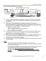
How the DynamicDNS service works
DynamicDNS service server
DNS
server
3. New address registered with
2. Camera reports new address
DNS server
On-site Network
Camera
ISP
4. DNS looks up
Internet
current address
1. Global IP address
changes
Off-site PC
5. Camera connection established
1. Your ISP assigns a global IP address to your Internet access account that
changes periodically. This is the address needed to access the camera over
the Internet.
2. When your ISP-assigned global IP address changes, your camera
automatically notifies the DynamicDNS service server of the new address in
the DynamicDNS. The camera notifies the DynamicDNS service server of the
new address in DynamicDNS in the following cases.
– When starting the camera
– When an update interval time has been set.
– When clicking the [Save] button
3. The DynamicDNS server contacts the Domain Name System (DNS) server
and registers your new global IP address to your chosen DynamicDNS
address (such as "bob.viewnetcam.com").
4. When you enter your DynamicDNS address in your web browser while away
from home or the office, the DNS server looks up the global IP address
assigned to your DynamicDNS address.
5. The DNS server finds your current global IP address and allows you to connect
to your camera.
Note
•
•
•
Ask your ISP about what type of IP address you are using.
Some ISPs assign you a local IP address. In this case, the DynamicDNS
service cannot be used.
If the camera is using a port number other than 80, the port number must
be specified at the end of the DynamicDNS URL. For example:
Using port 80: http://(Cameraname).viewnetcam.com
Using any other port: http://(Cameraname).viewnetcam.com:Port
Number
[For assistance, please call: 1-800-272-7033]
47
Operating Instructions
2.6
Setting the Date and Time
The Date and Time page allows you to set and confirm the date and time. The date
and time are used for the settings of the trigger setting, sensor log, operation time
and Buffered Image page.
Note
Saving a new date and time deletes all buffered images on the internal
memory.
1. Click [Date and Time] on the Setup page.
2. Set each parameter.
•
Set [Automatic Time Adjustment] to synchronize the time automatically
with an NTP server.
•
Clicking [Cancel] cancels your settings without saving changes.
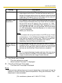
48
Operating Instructions
Setting
Time Setting
Description
•
Set the date and format (AM/PM or 24 H). The interface and available
values depend on the format. The date and time are used for the
settings of the trigger setting, sensor log, operation time and Buffered
Image page. Note that the format for the subject and file name of Emails by E-mail or FTP transfer can only be 24 h.
Automatic Time •
Adjustment
•
NTP (Network Time Protocol) server synchronizes the camera's
internal clock automatically every day. Check the box to enable it.
Set the NTP server IP address. Set 4 numbers (0—255)
and 3 periods, such as "192.168.0.253". Note that "0.0.0.0"
and "255.255.255.255" are not available. Set a host name
(1—255 characters). Note that [Space], ["], ['], [&], [<] and
[>] are not available.
Select your time zone.
•
Note
The camera will not synchronize to the NTP server if there
is more than a 1 hour difference between the NTP server
time and the camera's current time. This is to protect the
camera's time setting from fraudulent NTP server
tampering, incorrect time information, etc.
Adjust Clock for •
Daylight Saving
Time
During daylight saving time, the internal clock is turned
forward an hour. The clock will shift one hour forward at the
set time on the Start Day, and move back one hour at the
set time on the End Day. Check the box to enable it.
Note
An "s" is inserted between the date and time of the time stamp
when this feature is enabled. The time stamp is printed on
images transferred by the Image Transfer feature.
3. Click [Save] when finished.
•
•
The new settings are saved.
When finished, "Success!" is displayed.
4. Click [Go to Date and Time page].
•
The Date and Time page is displayed.
Note
Date and time settings become incorrect depending on the length of time the
camera is turned on and its internal temperature. Using the Automatic Time
Adjustment is recommended.
[For assistance, please call: 1-800-272-7033]
49
Operating Instructions
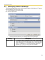
2.7
Changing Camera Settings
The Camera page allows you to set the camera name, white balance, AC power
source frequency and color night view.
1. Click [Camera] on the Setup page.
2. Set each parameter.
•
Clicking [Cancel] cancels your settings without saving changes.
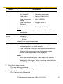
Setting
Camera Name
Description
•
•
The camera name is displayed on the Single Camera page.
Enter ASCII characters (see page 131) or characters from
other languages (1—15 characters for a 1-byte character
and 1—7 characters for a 2-byte character). Note that
[Space], ["], ['], [&], [<], and [>] are not available.
50
Operating Instructions
Setting
White Balance
Description
Select from the following options.
•
Auto (default)
— Automatic adjustment
•
Fixed Indoor
— Electric bulb (2800 K)
•
Fixed Fluorescent
(White)
— White (3600 K)
•
Fixed Fluorescent
(Daylight)
— Daylight (4000 K)
•
Fixed Outdoor
— Solar light (6000 K)
Note
The kelvin (symbol: K) is the standard unit for color
temperature.
AC Power
Source
Frequency
•
This setting may correct flickering caused by power line
frequency.
– 60 Hz (default)
– 50 Hz
Select 60 Hz in the United States.
Color Night
View
•
•
•
In the color night view mode, the camera image becomes
brighter in a low illuminance. The camera image returns to
normal operation in a bright location.
If you enable the color night view mode, refresh interval
may increase.
Subjects that are moving in low illumination may be
blurred, not distinguished, or not displayed.
Note
When the camera transmits a dark scene, the camera
image may become white, or horizontal lines may be
displayed on the screen. This is one of the characteristics
of a CMOS sensor. This is not a malfunction.
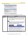
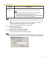
3. Click [Save] when finished.
•
•
The new settings are saved.
When finished, "Success!" is displayed.
4. Click [Go to Camera page].
•
The Camera page is displayed.
[For assistance, please call: 1-800-272-7033]
51
Operating Instructions
3
Registering Users
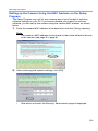
3.1
Changing the Authentication Setting and
Administrator User Name and Password
The Security: Administrator page allows you to change authentication, and the
administrator's user name and password. An authentication window allows
registered users to access the camera.
Note
•
If you access the camera for the first time, the window for setting the
administrator's user name and password is displayed. Make a note of the user
name and password so that you will not forget them.
•
The user name and password should be secured at your own responsibility.
Pay attention to the following points.
– Set a user name and password with as many characters as possible.
– Change the password regularly.
•
Setting [Permit access from guest users] (permitting access without a User
Name or Password) or [Permit access from guest users (mobile only)]
(permitting access without a User Name or Password) at General
Authentication risks the images being viewed by third parties. Control the
contents of the images accordingly.
IMPORTANT
•
It is important to limit access to the camera by use of a unique User Name and
a secret Password. Because the camera is accessed through the Internet it is
possible that the camera could be accessed by unknown individuals, including
those who are commonly known as "crackers" to whom you do not want to
allow access. The use of a unique User Name and a Password known only to
you will help insure that only authorized individuals are given access to the
camera. You have the option of proceeding without a User Name and
Password, but it is strongly recommended that you utilize these protections.
1. Click [Administrator] on the Setup page.
52
Operating Instructions
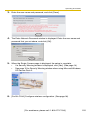
2. Set each parameter.
•
Clicking [Cancel] cancels your settings without saving changes.
Setting
General
Authentication
Description
Authentication has 3 phases.
•
If you set [Permit access from guest users], the camera
does not display the authentication window in camera
access. All guest users can view images without a user
name and password.
Note
If you set [Permit access from guest users], [Login] tab is
displayed at the top of the page. After you log in as an
administrator (see page 56), the Setup page and the
Maintenance page can be accessed.
•
•
If you set [Permit access from guest users (mobile only)],
an authentication window is not displayed even if you
access the cell phone page. All guest users can view
images without a user name and password.
If you set [Do not permit access from guest users], an
authentication window is displayed to access the camera.
Users must enter the user name and password.
[For assistance, please call: 1-800-272-7033]
53
Operating Instructions
Setting
User Name/
Password
Description
•
•
User Name (6 to 15 characters): Enter the user name.
Password (6 to 15 characters): Enter the password.
Note
•
•
The password must be different from the user name.
Retype Password: Reenter the password.
Enter ASCII characters (see page 131). Note that [Space],
["], ['], [&], [<], [>] and [:] are not available.
Note
•
•
•
When setting authentication, set the user name and password, and save
them.
When users other than an administrator are accessing the camera, the
[Setup] and [Maintenance] tabs will not be displayed.
The user name and password are case sensitive.
3. Click [Save] when finished.
•
•
The new settings are saved.
When finished, "Success!" is displayed.
4. Click [Go to Security: Administrator page].
•
The Security: Administrator page is displayed.
Note
When the user name and password have been changed, the camera displays
an authentication window. Enter the user name and password, and click [OK].
54
Operating Instructions
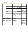
Administrator/General Users/Guest Users
The camera has 3 user levels (administrator, general users and guest users).
Items
Administrator
General Users
Guest Users
User Name and
Password
Required
Required
Not Required
Number of Users
1
50
—
Accessible Pages
All Pages
Access Level
All Operations
Pages Except For Pages Except For
Setup and
Setup and
Maintenance page Maintenance page
Access level can
be set for each
general user (see
page 57).
Access level can
be set for guest
users (see page
57).
Note
Guest users mean unregistered users. Set [Permit access from guest users]
or [Permit access from guest users (mobile only)] on the Security:
Administrator page (see page 52) to allow access from guest users.
[For assistance, please call: 1-800-272-7033]
55
Operating Instructions
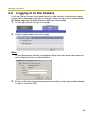
3.2
Logging in to the Camera
If you set [Permit access from guest users] on the Security: Administrator page,
[Login] tab is displayed at the top of the page. After you log in as an administrator,
the Setup page and the Maintenance page can be accessed.
1. Click [Login] tab at the top of the page.
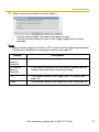
2. Check a login mode, and click [Login].
Note
The authentication window is displayed. Enter the user name and password
set for General Users or Administrator.
3. Enter a valid user name and password according to the Login mode selected
in step 2, and click [OK].
56
Operating Instructions
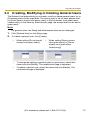
3.3
Creating, Modifying or Deleting General Users
The General User page allows you to create, modify or delete general users. Up to
50 general users can be registered. The access level is set for each general user.
If you set [Permit access from guest users] or [Permit access from guest users
(mobile only)] on the Security: Administrator page, the access level can be set for
guest users.
Note
For general users, the Setup and Maintenance tabs are not displayed.
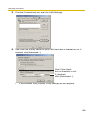
1. Click [General User] on the Setup page.
2. To create a general user, click [Create].
•
When setting [Do not permit
access from guest users]
•
To change the settings of general users or guest users, select their
name and click [Modify]. The modification page is displayed.
To delete a general user, select the name and click [Delete]. The
confirmation page is displayed.
•
•
When setting [Permit access
from guest users] or [Permit
access from guest users
(mobile only)]
[For assistance, please call: 1-800-272-7033]
57
Operating Instructions
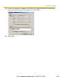
3. Set each parameter.
•
Settings for general users
•
Clicking [Cancel] takes you back to the previous page without
saving changes.
Setting
•
Settings for guest users
Description
User ID List
•
•
Up to 50 general users can be registered.
The list is used to modify or delete general user settings.
User Name/
Password
•
•
User Name (6 to 15 characters): Enter the user name.
Password (6 to 15 characters): Enter the password.
Note
•
•
Access Level
The password must be different from the user name.
Retype Password: Reenter the password.
Enter ASCII characters (see page 131). Note that [Space],
["], ['], [&], [<], [>] and [:] are not available.
An access level is set for each general user.
•
Level 1 : Only the camera images can be viewed.
•
Level 2 : The camera images can be viewed and the
brightness can be adjusted.
4. Click [Save] when finished.
•
•
The new settings are saved.
When finished, "Success!" is displayed.
5. Click [Go to General User page].
•
The General User page is displayed.
58
Operating Instructions
4
Buffering or Transferring Images
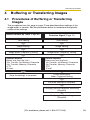
4.1
Procedures of Buffering or Transferring
Images
The procedures from this page to page 70 are described about settings of the
image buffer or transfer. See the procedures below to understand the general
outline of the settings.
Buffer/Transfer by Timer (Page 60)
Buffer/Transfer by Motion
Detection Signal (Page 70)
Time Setting
Time Setting
Image Setting
Image Setting
Image Buffer Frequency Setting
Image Buffer Frequency Setting
Transfer Method
(Select one from the lists.)
• No Transfer, No Memory Overwrite
• No Transfer, Memory Overwrite
• FTP
• E-mail
Save the settings to complete.
Transfer Method
(Select one from the lists.)
• No Transfer, No Memory Overwrite
• No Transfer, Memory Overwrite
• FTP
• E-mail
E-mail Notification
When Triggered Setting
Save the settings to complete.
Changing Motion Detection Sensitivity
(Page 83)
Notifying the Sensor Log
(Page 86)
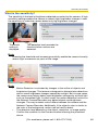
[For assistance, please call: 1-800-272-7033]
59
Operating Instructions
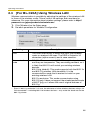
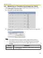
4.2
Buffering or Transferring Images by Timer
The Trigger page allows you to enable image buffer/transfer by E-mail or FTP.
1. Click [Trigger] on the Setup page.
2. Click a No. to enable buffer/transfer.
3. Check [Enable Image Buffer/Transfer], and select [Timer] for the trigger, and
click [Next>].
Note
•
•
•
Click [Delete Buffered Images] to delete images already buffered.
Click [Save] to save the settings. The buffered images will be deleted.
Clicking [Cancel] takes you back to the Trigger page without saving
changes.
Setting
Enable Image
Buffer/Transfer
Description
•
Check the box to enable the Trigger setting. Uncheck the
box to disable it.
60
Operating Instructions
Setting
Trigger
Description
•
•
Selecting [Timer] enables the camera to buffer/transfer
images during the specified date and time by timer.
Selecting [Motion Detection] enables the camera to buffer/
transfer images when the motion is detected during the
specified date and time.
4. Set the time, and click [Next>].
Note
The timer works by an internal clock. Set the date and time before using timer
buffer/transfer (see page 48).
•
Clicking [<Back] takes you back to the previous page.
•
Clicking [Cancel] takes you back to the Trigger page without saving
changes.
Setting
Description
Day of the week •
Check the box to enable the day. Uncheck the box to
disable it.
Active Time of
Trigger
To set a trigger time, check the time option and set a time
period. Check the [Always] option if you are not specifying
a time period.
•
5. Set the image settings, and click [Next>].
•
•
Clicking [<Back] takes you back to the previous page.
Clicking [Cancel] takes you back to the Trigger page without saving
changes.
[For assistance, please call: 1-800-272-7033]
61
Operating Instructions
Setting
Description
Image
Resolution
•
Select an image resolution (640 × 480, 320 × 240 (default)
or 160 × 120 pixels) for the buffer/transfer.
Image Quality
•
Select the image quality.
[Favor Clarity] optimizes for good quality.
[Standard] offers standard quality. (default)
[Favor Motion] optimizes for enhanced motion.
[Mobile Phone] is for a transfer to a cell phone.
Note
640 × 480 pixels cannot be set for a transfer to a cell
phone.
6. Set the image buffer frequency, and click [Next>].
Note
Due to the network environment, object and the number of simultaneous
accesses, the camera may not record the number of images that you set. In
this case, set the image buffer frequency longer.
•
Clicking [<Back] takes you back to the previous page.
•
Clicking [Cancel] takes you back to the Trigger page without saving
changes.
Setting
Image Buffer
Frequency
Description
•
Select an image buffer frequency to buffer or transfer the
image. (1 image per hour—15 images per second)
62
Operating Instructions
7. Select the transfer method, and click [Next>].
•
•
Clicking [<Back] takes you back to the previous page.
Clicking [Cancel] takes you back to the Trigger page without saving
changes.
Note
If you transfer images by E-mail or FTP, confirm that the default gateway and
DNS server addresses are assigned correctly (see page 31).
Setting
Description
No Transfer, No •
Memory
Overwrite
If the internal memory is full, the camera stops buffering.
No Transfer,
Memory
Overwrite
•
If the internal memory is full, the camera deletes the old
images, and continues to buffer the image.
FTP
•
The camera transfers the image to an FTP server (see
page 64).
E-mail
•
The camera transfers the image by E-mail (see page 66).
[For assistance, please call: 1-800-272-7033]
63
Operating Instructions
When you set [FTP] for Transfer Method
Select [FTP], and click [Next>]. The following page is displayed.
•
•
Clicking [<Back] takes you back to the previous page.
Clicking [Cancel] takes you back to the Trigger page without saving
changes.
64
Operating Instructions
Setting
Description
Server IP
•
Address or
Host Name*1
If you set a server IP address, set 4 numbers (0—255) and 3
periods, such as "192.168.0.253". Note that "0.0.0.0" and
"255.255.255.255" are not available. Or set a host name (1—
255 characters).
Port No.
•
Enter a number (1—65535). Usually set to 21.
Login ID*2
•
If your ISP requires a login ID, set it (0—63 characters).
Password*2
•
If your ISP requires a password, set it (0—63 characters).
Login Timing •
Select the login setting for the FTP server. If you set [One
Time] and the image buffer frequency value is set within 1
minute, the camera logs in to the server only once. This can
reduce transfer time.
Upload File
Name*1
•
Set a file name on the FTP server to receive the transferred
files. Enter 1—234 characters. Entering "\" creates directories
for a file. (E.g. NetworkCamera\image.jpg)
Overwrite
Setting
•
Selecting [Overwrite File] overwrites the image on the server
with a newer image. Selecting [Save as New File with Time
Stamp] saves the image attaching time stamps on the file
name, and the images are not overwritten.
(E.g. image20050101093020500.jpg) The underlined
numbers mean "9h30min20s500ms on January 1, 2005". The
letter "s" is inserted after the day when referring to a daylight
saving time zone.
Data
Transfer
Method
•
Select [Passive Mode] normally. If the transfer does not work,
select [Active Mode] and check the operation.
*1
*2
Note that [Space], ["], ['], [&], [<] and [>] are not available.
Note that ["] is not available.
[For assistance, please call: 1-800-272-7033]
65
Operating Instructions
When you set [E-mail] for Transfer Method
Select [E-mail], and click [Next>]. The following page is displayed.
•
•
Clicking [<Back] takes you back to the previous page.
Clicking [Cancel] takes you back to the Trigger page without saving
changes.
Note
•
•
The camera works only with an SMTP (Simple Mail Transfer Protocol)
server. It does not work with mail servers like "Hotmail®" that use a web
browser.
The subject name by E-mail transfer uses only 24 h format. The file name
is "image.jpg".
E.g. "image:20050101093020500".
The underlined numbers mean "9h30min20s500ms on January 1, 2005".
The letter "s" is inserted after the day when referring to a daylight saving
time zone.
66
Operating Instructions
Setting
Description
SMTP Server IP •
Address or Host
Name*1
If you set a server IP address, set 4 numbers (0—255) and
3 periods, such as "192.168.0.253". Note that "0.0.0.0" and
"255.255.255.255" are not available. Or set a host name
(1—255 characters).
Port No.
•
Enter a number (1—65535). Usually set to 25.
Reply E-mail
Address*2
•
Set the sender's E-mail address. We recommend you to
set the administrator's E-mail address.
Destination Email Address*2
1—3
•
Set the destination E-mail address (up to 3).
Subject*2
•
Enter a subject with ASCII characters (see page 131) or
characters from other languages (0—44 characters for a
1-byte character and 0—22 characters for a 2-byte
character).
Text*2
•
Enter text with ASCII characters (see page 131) or
characters from other languages (0—63 characters for a
1-byte character and 0—31 characters for a 2-byte
character). Note that [end-of-line] key is not available.
[For assistance, please call: 1-800-272-7033]
67
Operating Instructions
Setting
How to
authenticate
*1
*2
Description
You can select the authentication method: [No authentication],
[POP before SMTP authentication] and [SMTP authentication].
POP server authentication may be required by your ISP. In
that case, set POP before SMTP authentication.
•
No authentication: No authentication when sending an email.
•
POP before SMTP authentication: Some SMTP servers
that send e-mails do not have an authentication feature.
Therefore, the camera uses the authentication of a POP
server that receives e-mails, before sending e-mails.
–
POP3 Server
IP Address or
Host Name*1:
If you set a server IP address, set 4
numbers (0—255) and 3 periods, such as
"192.168.0.253". Note that "0.0.0.0" and
"255.255.255.255" are not available. Or
set a host name (1—255 characters).
–
Port No.:
Enter a number (1—65535). Usually set
to 110.
–
Login ID*2:
If your ISP requires a login ID to log in to
a POP3 server, set it (1—63 characters).
–
Password*2:
If your ISP requires a password to log in
to a POP3 server, set it (0—63
characters).
•
SMTP authentication: Users are authenticated by user
name and password on the SMTP server. Your ISP must
support the SMTP authentication. Only the LOGIN and
PLAIN authentication mechanisms are supported.
–
Login ID*2:
If your ISP requires a login ID to log in to
an SMTP server, set it (1—63
characters).
–
Password*2:
If your ISP requires a password to log in
to an SMTP server, set it (0—63
characters).
Note that [Space], ["], ['], [&], [<] and [>] are not available.
Note that ["] is not available.
68
Operating Instructions
8. Confirm the settings, and click [Save].
•
•
The new settings are saved.
When finished, "Success!" is displayed.
9. Click [Go to Trigger page].
•
The Trigger page is displayed.
Note
•
If you are buffering images to the internal memory, the following
operations also delete all buffered images.
– Turning off the camera.
– Saving the Date and Time page.
– Restarting, updating firmware or resetting the camera to factory
default.
[For assistance, please call: 1-800-272-7033]
69
Operating Instructions
4.3
Buffering or Transferring Images by Motion
Detection Signal
The Trigger page allows you to enable image buffer/transfer by E-mail or FTP.
Note
•
•
•
•
•
The level of motion detection depends on resolution, image quality, and
the object being viewed. Check the level by performing motion detection
recording. (See page 83)
Enabling Motion Detection delays the frame rate of the camera.
A change to light or wind conditions may detect motions accidentally.
Motion Detection may not work in dark areas.
Objects moving fast may not be detected.
1. Click [Trigger] on the Setup page.
2. Click a No. to enable buffer/transfer.
3. Check [Enable Image Buffer/Transfer], select [Motion Detection] for the trigger,
and click [Next>].
70
Operating Instructions
Note
•
•
•
Click [Delete Buffered Images] to delete images already buffered.
Click [Save] to save the settings. The buffered images will be deleted.
Clicking [Cancel] takes you back to the Trigger page without saving
changes.
Setting
Description
Enable Image
Buffer/Transfer
•
Check the box to enable the Trigger setting. Uncheck the
box to disable it.
Trigger
•
Selecting [Timer] enables the camera to buffer/transfer
images during the specified date and time by timer.
Selecting [Motion Detection] enables the camera to buffer/
transfer images when the motion is detected during the
specified date and time.
•
4. Set the time, and click [Next>].
Note
The timer works by an internal clock. Set the date and time before using timer
buffer/transfer (see page 48).
•
Clicking [<Back] takes you back to the previous page.
•
Clicking [Cancel] takes you back to the Trigger page without saving
changes.
Setting
Description
Day of the week •
Check the box to enable the day. Uncheck the box to
disable it.
Active Time of
Trigger
To set a trigger time, check the time option and set a time
period. Check [Always] if you are not specifying a time
period.
•
[For assistance, please call: 1-800-272-7033]
71
Operating Instructions
5. Set the image settings, and click [Next>].
•
•
Clicking [<Back] takes you back to the previous page.
Clicking [Cancel] takes you back to the Trigger page without saving
changes.
Setting
Description
Image
Resolution
•
Select an image resolution (640 × 480, 320 × 240 (default)
or 160 × 120 pixels) for the buffer/transfer.
Image Quality
•
Select the image quality.
[Favor Clarity] optimizes for good quality.
[Standard] offers standard quality. (Default)
[Favor Motion] optimizes for enhanced motion.
[Mobile Phone] is for a transfer to a cell phone.
Note
640 × 480 pixels cannot be set for a transfer to a cell
phone.
72
Operating Instructions
6. Set the image buffer frequency and the Motion deactivation time, and click
[Next>].
Note
Due to the network environment, object and the number of simultaneous
accesses, the camera may not record the number of images that you set. In
this case, set the image buffer frequency longer.
•
Clicking [<Back] takes you back to the previous page.
•
Clicking [Cancel] takes you back to the Trigger page without saving
changes.
Setting
Enable Pretrigger Image
Buffer
Description
•
•
Enable Posttrigger Image
Buffer
•
•
Check the box to enable the setting. The camera buffers or
transfers the image right before the motion detection signal
is detected.
Set an interval, number of images to buffer and total
number (see page 132). The number of buffered images
may not match the total number due to memory capacity,
image resolution, image quality or what object you view.
Check the box to enable the setting. The camera buffers or
transfers the image right after the motion detection signal
is detected.
Set an interval, number of images to buffer and total
number (see page 132). The number of buffered images
may not match the total number due to memory capacity,
image resolution, image quality or what object you view.
[For assistance, please call: 1-800-272-7033]
73
Operating Instructions
Setting
Motion
deactivation
time
Description
•
•
Set the length of time during which the Motion Detection
cannot be triggered after saving images temporarily or
transmitting them. This function is recommended to
prevent sending too many E-mails to a cell phone.
After detecting motions, the camera does not detect
motions during motion deactivation time, so some images
may not be captured.
Note
The internal memory cannot buffer images during motion
deactivation time. Because of this, images taken before
detection are not saved in internal memory, and so cannot
be received. Depending on the settings for image buffer/
transfer, even if it is set to, for example, take "1 image per
second, and store 10 images, before detection", because
the images are not stored in internal memory, if the Motion
Detection detects something directly after the end of
motion deactivation time, the images may not be saved.
Ten seconds after the end of motion deactivation time,
images can be received as specified in the settings (see
page 82).
74
Operating Instructions
7. Select the transfer method, and click [Next>].
•
•
Clicking [<Back] takes you back to the previous page.
Clicking [Cancel] takes you back to the Trigger page without saving
changes.
Note
If you transfer images by E-mail or FTP, confirm that the default gateway and
DNS server addresses are assigned correctly (see page 31).
Setting
Description
No Transfer, No •
Memory
Overwrite
If the internal memory is full, the camera stops buffering.
No Transfer,
Memory
Overwrite
•
If the internal memory is full, the camera deletes the old
images, and continues to buffer the image.
FTP
•
The camera transfers the image to an FTP server (see
page 76).
E-mail
•
The camera transfers the image by E-mail (see page 78).
[For assistance, please call: 1-800-272-7033]
75
Operating Instructions
When you set [FTP] for Transfer Method
Select [FTP], and click [Next>]. The following page is displayed.
•
•
Clicking [<Back] takes you back to the previous page.
Clicking [Cancel] takes you back to the Trigger page without saving
changes.
76
Operating Instructions
Setting
Description
Server IP
•
Address or
Host Name*1
If you set a server IP address, set 4 numbers (0—255) and 3
periods, such as "192.168.0.253". Note that "0.0.0.0" and
"255.255.255.255" are not available. Or set a host name (1—
255 characters).
Port No.
•
Enter a number (1—65535). Usually set to 21.
Login ID*2
•
If your ISP requires a login ID, set it (0—63 characters).
Password*2
•
If your ISP requires a password, set it (0—63 characters).
Login Timing •
Select the login setting for the FTP server. If you set [One
Time] and the image buffer frequency value is set within 1
minute, the camera logs in to the server only once. This can
reduce transfer time.
Upload File
Name*1
•
Set a file name on the FTP server to receive the transferred
files. Enter 1—234 characters. Entering "\" creates directories
for a file. (E.g. NetworkCamera\image.jpg)
Overwrite
Setting
•
Selecting [Overwrite File] overwrites the image on the server
with a newer image. Selecting [Save as New File with Time
Stamp] saves the image attaching time stamps on the file
name, and the images are not overwritten.
(E.g. image20050101093020500.jpg) The underlined
numbers mean "9h30min20s500ms on January 1, 2005". The
letter "s" is inserted after the day when referring to a daylight
saving time zone.
Data
Transfer
Method
•
Select [Passive Mode] normally. If the transfer does not work,
select [Active Mode] and check the operation.
*1
*2
Note that [Space], ["], ['], [&], [<] and [>] are not available.
Note that ["] is not available.
[For assistance, please call: 1-800-272-7033]
77
Operating Instructions
When you set [E-mail] for Transfer Method
Select [E-mail], and click [Next>]. The following page is displayed.
•
•
Clicking [<Back] takes you back to the previous page.
Clicking [Cancel] takes you back to the Trigger page without saving
changes.
78
Operating Instructions
Note
•
The camera works only with an SMTP (Simple Mail Transfer Protocol)
server. It does not work with mail servers like "Hotmail" that use a web
browser.
The subject name by E-mail transfer uses only 24 h format. The file name
is "image.jpg".
E.g. "image:20050101093020500".
The underlined numbers mean "9h30min20s500ms on January 1, 2005".
The letter "s" is inserted after the day when referring to a daylight saving
time zone.
•
Setting
Description
SMTP Server IP •
Address or Host
Name*1
If you set a server IP address, set 4 numbers (0—255) and
3 periods, such as "192.168.0.253". Note that "0.0.0.0" and
"255.255.255.255" are not available. Or set a host name
(1—255 characters).
Port No.
•
Enter a number (1—65535). Usually set to 25.
Reply E-mail
Address*2
•
Set the sender's E-mail address. We recommend you to
set the administrator's E-mail address.
Destination Email Address*2
1—3
•
Set the destination E-mail address (up to 3).
Subject*2
•
Enter a subject with ASCII characters (see page 131) or
characters from other languages (0—44 characters for a 1byte character and 0—22 characters for a 2-byte
character).
Text*2
•
Enter text with ASCII characters (see page 131) or
characters from other languages (0—63 characters for a 1byte character and 0—31 characters for a 2-byte
character). Note that [end-of-line] key is not available.
[For assistance, please call: 1-800-272-7033]
79
Operating Instructions
Setting
How to
authenticate
*1
*2
Description
You can select the authentication method: [No authentication],
[POP before SMTP authentication] and [SMTP authentication].
POP server authentication may be required by your ISP. In
that case, set POP before SMTP authentication.
•
No authentication: No authentication when sending an email.
•
POP before SMTP authentication: Some SMTP servers
that send e-mails do not have an authentication feature.
Therefore, the camera uses the authentication of a POP
server that receives e-mails, before sending e-mails.
–
POP3 Server
IP Address or
Host Name*1:
If you set a server IP address, set 4
numbers (0—255) and 3 periods, such as
"192.168.0.253". Note that "0.0.0.0" and
"255.255.255.255" are not available. Or
set a host name (0—255 characters).
–
Port No.:
Enter a number (1—65535). Usually set
to 110.
–
Login ID*2:
If your ISP requires a login ID to log in to
a POP3 server, set it (1—63 characters).
–
Password*2:
If your ISP requires a password to log in
to a POP3 server, set it (0—63
characters).
•
SMTP authentication: Users are authenticated by user
name and password on the SMTP server. Your ISP must
support the SMTP authentication. Only the LOGIN and
PLAIN authentication mechanisms are supported.
–
Login ID*2:
If your ISP requires a login ID to log in to
an SMTP server, set it (1—63
characters).
–
Password*2:
If your ISP requires a password to log in
to an SMTP server, set it (0—63
characters).
Note that [Space], ["], ['], [&], [<] and [>] are not available.
Note that ["] is not available.
80
Operating Instructions
8. After you confirm the settings and click [Next>], set E-mail notification and click
[Next>].
•
If you select [Enable], the E-mail Notification When Triggered page is
displayed. Enter the settings referring to page 78 — page 80.
Setting
Description
Disable
•
The camera does not send an E-mail notification when
buffering or transferring images.
Enable
•
The camera sends an E-mail notification (up to 3
destinations) when buffering or transferring images.
9. Click [Save] after confirming the settings.
•
•
The new settings are saved.
When finished, "Success!" is displayed.
[For assistance, please call: 1-800-272-7033]
81
Operating Instructions
10. Click [Go to Trigger page].
•
The Trigger page is displayed.
Note
•
If you set a short interval when transferring to a cell phone, many E-mails
will be sent, which may lead to a large phone bill. Therefore, we
recommend you to set a long interval. 1 image per minute frequency is
recommended.
•
Motion Detection transfer stops operating until after the camera finishes
all transfers. For example, if the camera transfers 3 images per minute and
6 images in total by setting 1 minute for motion deactivation time, the
sensor will follow the pattern below.
120 seconds
1st
Detectable
2nd 3rd
4th
5th
1 minute
6th
Undetectable
Motion
deactivation time
Undetectable Detectable
A Motion Detection signal is detected.
•
If you are buffering images to the internal memory, the following
operations also delete all buffered images.
– Turning off the camera.
– Saving the Date and Time page.
– Restarting, updating firmware or resetting the camera to factory
default.
82
Operating Instructions
4.4
Setting the Motion Detection
The Motion Detection page allows you to adjust the sensitivity of Motion Detection.
Threshold: If the threshold is set low, this function detects nearly all movements.
Sensitivity: If you set sensitivity high, the amplitude of the motion detection bar gets
jumpy.
1. Click [Motion Detection] on the Setup page.
2. Click the Motion Detection bar in Threshold to set the threshold level.
3. Click the Motion Detection bar in Sensitivity to set the sensitivity level.
4. Click [Save] to save the settings.
•
Clicking [Cancel] cancels your settings without saving changes.
5. Click [Go to Motion Detection page].
•
The Motion Detection page is displayed.
Setting
Description
Threshold
•
Adjusts the threshold for Motion Detection. As the value is
set lower, the sensor will detect motions of smaller
changes.
Sensitivity
•
Adjusts the sensitivity for Motion Detection. As the value is
set higher, the amplitude of the Motion Detection bar will
become greater.
Preview
Display the current threshold and detection level.
•
The threshold is the line between the green and red bar.
•
The detection level is the line between the dark red and light red color.
Note
The Threshold and Sensitivity settings are enabled after saving, and reflected
in preview.
[For assistance, please call: 1-800-272-7033]
83
Operating Instructions
Threshold
Note
No responsibility will be taken by our company with respect to consequences
resulting from the use of the Motion Detection feature. The Motion Detection
feature is not suitable and not recommended for uses that require a high
reliability constantly such as surveillance, etc.
What is the threshold?
The threshold is the minimum value for the camera to detect motions on the image
during the motion detection buffering. Setting the threshold lower allows subtler
changes to be detected. Setting the threshold higher allows only bigger changes
that might occupy half the image to be detected.
84
Operating Instructions
What is the sensitivity?
The sensitivity is the level of brightness detected as motion by the camera. A high
sensitivity setting enables the camera to detect slight brightness changes. Lower
the sensitivity to make the camera detect only big brightness changes.
Threshold
setting is
displayed.
The detection level exceeds the
threshold when motions are
detected.
Note
Lowering the threshold and increasing sensitivity enable the camera to easily
detect slight movements on parts of the image.
Note
•
•
Motion Detection is activated by changes in the outline of objects and
brightness changes. This feature is designed to alleviate false detections
due to overall brightness changes caused by sunlight. But in some cases,
the camera may falsely detect rapid brightness changes by artificial light
such as fluorescent light. In other cases, the motion detection function on
the Network Camera Recorder may detect objects and brightness
changes. The way to detect motion differs between the camera and the
Network Camera Recorder. Additionally, if the object's color is similar to
the color of the background, motion can be hard to detect.
The detection level depends on the object, resolution, or image quality.
Confirm the condition on the Preview window following the procedure
above.
[For assistance, please call: 1-800-272-7033]
85
Operating Instructions
4.5
Setting Sensor Log Notification
A sensor log sent once a day at a specified time can be checked. To enable Sensor
Log, set Motion Detection for Trigger Setting and check [Enable].
1. Click [Sensor Log] on the Setup page.
When enabling the image/buffer transfer setting and selecting Motion
Detection in the Trigger page, the Sensor log window is displayed.
2. Set each parameter.
Note
•
•
•
Click [Save] to save the settings.
Clicking [Cancel] cancels your settings without saving changes.
Clicking [Save] deletes new-arrival sensor logs.
86
Operating Instructions
Setting
Description
A setup of
operation
•
Sensor log operation can be set here.
Time
•
Set the day of the week and time to send sensor logs via
E-mail.
SMTP Server IP •
Address or Host
Name*1
If you set a server IP address, set 4 numbers (0—255) and
3 periods, such as "192.168.0.253". Note that "0.0.0.0" and
"255.255.255.255" are not available. Or set a host name
(1—255 characters).
Port No.
•
Enter a number (1—65535). Usually set to 25.
Reply E-mail
Address*2
•
Set the sender's E-mail address. We recommend you to
set the administrator's E-mail address.
Destination E•
mail Address 13*2
Set the destination E-mail address (up to 3).
Subject*2
Enter a subject with ASCII characters (see page 131) or
characters from other languages (0—44 characters for a 1byte character and 0—22 characters for a 2-byte
character).
•
[For assistance, please call: 1-800-272-7033]
87
Operating Instructions
Setting
How to
authenticate
*1
*2
Description
You can select the authentication method: [No authentication],
[POP before SMTP authentication] and [SMTP authentication].
POP server authentication may be required by your ISP. In
that case, set POP before SMTP authentication.
•
No authentication: No authentication when sending an email.
•
POP before SMTP authentication: Some SMTP servers
that send e-mails do not have an authentication feature.
Therefore, the camera uses the authentication of a POP
server that receives e-mails, before sending e-mails.
–
POP3 Server
IP Address or
Host Name*1:
If you set a server IP address, set 4
numbers (0—255) and 3 periods, such as
"192.168.0.253". Note that "0.0.0.0" and
"255.255.255.255" are not available. Or
set a host name (0—255 characters).
–
Port No.:
Enter a number (1—65535). Usually set
to 110.
–
Login ID*2:
If your ISP requires a login ID to log in to
a POP3 server, set it (1—63 characters).
–
Password*2:
If your ISP requires a password to log in
to a POP3 server, set it (0—63
characters).
•
SMTP authentication: Users are authenticated by user
name and password on the SMTP server. Your ISP must
support the SMTP authentication. Only the LOGIN and
PLAIN authentication mechanisms are supported.
–
Login ID*2:
If your ISP requires a login ID to log in to
an SMTP server, set it (1—63
characters).
–
Password*2:
If your ISP requires a password to log in
to an SMTP server, set it (0—63
characters).
Note that [Space], ["], ['], [&], [<] and [>] are not available.
Note that ["] is not available.
88
Operating Instructions
5
Using Other Features
5.1
Changing Initial Settings on the Single
Camera page or the Multi-Camera page
The Image Display page allows you to change the initial settings (display settings
when a user accesses the camera) for the Single Camera, Multi-Camera, Limit
Continuous Motion JPEG, Language and Banner Display.
1. Click [Image Display] on the Setup page.
2. Set each parameter.
•
Clicking [Cancel] cancels your settings without saving changes.
[For assistance, please call: 1-800-272-7033]
89
Operating Instructions
Setting
Description
Image Resolution
•
Select the image resolution.
640 × 480 pixels (Only for the Single Camera page)
320 × 240 pixels (default)
160 × 120 pixels (Only for the Multi-Camera page)
Image Quality
•
Select the image quality.
[Favor Clarity] optimizes for good quality.
[Standard] offers standard quality. (default)
[Favor Motion] optimizes for enhanced motion.
Refresh Interval
•
Select a refresh interval.
(Motion, 3 s, 5 s, 10 s, 30 s, and 60 s)
•
Set the time to change the video (Motion JPEG) to still
images. (10 seconds—Unlimited)
•
Set a refresh interval after the image is changed to still
images. (3-second interval—60-second interval)
•
Select the initial language from English, Japanese,
French, German, Italian, Spanish, Simplified Chinese,
Russian or Korean. The selected language is displayed
as the initial language on the Top, Single Camera,
Multi-Camera and Buffered Image pages. If you select
English, Japanese, French or Simplified Chinese, all
pages can be changed. But if you select another
language, the Setup, Maintenance and Support pages
are displayed in English.
Limit Continuous
Motion JPEG
•
Limit time of
Continuous
Motion JPEG
•
Refresh
Interval
Language
90
Operating Instructions
Setting
Banner Display
Description
When checked to [Enable], the setting will be enabled.
When unchecked, the setting will be disabled.
Note
•
•
•
Banner user
•
When the Banner Display is enabled, the camera
accesses the Image URL every time the Single
Camera page is displayed. The intermittent and
continuous switching of the Single page burdens
the PC that stores the image linked with the URL.
If the image URL linked with an image stored in a
PC that requires an authentication is set, the
authentication window will be displayed when
displaying the Single page.
All users
: The banner can be displayed for
all users.
Administrator only : The banner can be displayed for
the administrator.
General user only : The banner can be displayed for
the general user.
•
Image URL*1
•
Enter the image URL you want to display as a banner.
When [Enable] is checked, enter the image URL. (1—
127 characters)
•
Link URL*1
•
Enter the target URL you want to display when clicking
the banner. (0—127 characters)
*1
Note that [Space], ["], ['], [&], [<], and [>] are not available.
3. Click [Save] when finished.
•
•
The new settings are saved.
When finished, "Success!" is displayed.
4. Click [Go to Image Display page].
•
The Image Display page is displayed.
[For assistance, please call: 1-800-272-7033]
91
Operating Instructions
5.2
Configuring Multiple Cameras
The Multi-Camera Setup page allows you to configure camera IP addresses and
camera names to view multiple images on the Multi-Camera page. These
configurations are required to use the Multi-Camera page. Up to 12 cameras can
be configured. The Selfcamera is registered at No. 1 by default.
1. Click [Multi-Camera] on the Setup page.
2. Click Add.
Note
•
•
If you click the camera number, the modification page is displayed.
Camera settings can be modified or deleted here.
If you configured multiple cameras, you can change the camera number.
Select the number, and click [Move].
3. Set each parameter.
•
•
Clicking [Cancel] cancels your settings without saving changes.
By clicking [Clicking this link, enters this camera's settings.], the settings
of the Selfcamera are entered automatically. "--" is displayed for the Port
No, and the model no. is displayed for the Camera Name.
92
Operating Instructions
Setting
Display
Description
•
Check this box to enable the camera.
IP Address or
Host Name*2
•
Set an IP address or host name to enable the camera.
Port No.
•
Set a port number (1—65535).
*1
Camera Name*3 •
*1
*2
*3
This camera name is displayed only on the Multi-Camera
page.
Set 4 numbers (0—255) and 3 periods, such as "192.168.0.253". Note that
"0.0.0.0" and "255.255.255.255" are not available.
Enter ASCII characters for the host name (see page 131). Note that [Space],
["], ['], [#], [&], [%], [=], [+], [?], [<] and [>] are not available.
Enter 1—255 characters.
You can enter ASCII characters (see page 131) or characters from other
languages (1—15 characters for a 1-byte character and 1—7 characters for a
2-byte character). Note that [Space], ["], ['], [#], [&], [%], [=], [+], [?], [:], [<], and
[>] are not available.
Note
•
•
If your camera will only be accessed on your local network, use each
camera's local IP address and port number.
If you intend to access your camera from the Internet, you must use each
camera's host name (global IP address) and the port number.
4. Click [Save] when finished.
•
•
The new settings are saved.
The Multi-Camera Setup page is displayed.
[For assistance, please call: 1-800-272-7033]
93
Operating Instructions
5.3
Specifying Operation Time
The Operation Time page allows you to limit the time that the camera is in use. The
camera image turns to a gray screen outside operation time.
Note
•
•
Your privacy may be compromised if the time period is set incorrectly.
Confirm the time period after the setup.
If you access the camera as an administrator, you can view the image
outside the time period.
1. Click [Operation Time] on the Setup page.
2. Click a No. to set the operation time.
Note
If No. 1—7 are disabled, the camera can always be operated.
3. Check [Enable], set the time, and click [Save]
•
Clicking [Cancel] takes you back to the previous page without saving
changes.
94
Operating Instructions
Setting
Enable
Description
•
Check the box to enable the setting. Uncheck the box to
disable it.
Day of the week •
Check the box to enable the day. Uncheck the box to
disable it.
Operation Time
To set an operation time, check the time option and set a
time period. Check the [Always] option if you are not
specifying a time period.
•
4. Click [Save] when finished.
•
•
The new settings are saved.
The Operation Time page is displayed.
About Operation Time
In the operation time settings, the enabled settings take priority over the disabled
settings. Therefore, if Monday or Tuesday is disabled in a setting but enabled in
other settings, the camera can be operated on both Monday and Tuesday.
[For assistance, please call: 1-800-272-7033]
95
Operating Instructions
5.4
Changing the Indicator Display
The Indicator Control page allows you to select an operation for the indicator. There
are three options.
•
Turn indicator on when camera is on.
•
Turn indicator on during camera access.
•
Never turn indicator on.
1. Click [Indicator Control] on the Setup page.
2. Select an option.
Setting
Description
Turn indicator
•
on when camera
is on.
The indicator always turns on or blinks. See page 3 and
page 4 of Troubleshooting on the CD-ROM.
Turn indicator
•
on during
camera access.
The indicator turns green when the camera is being
accessed.
Never turn
indicator on.
The indicator always turns off.
•
•
Clicking [Cancel] cancels your settings without saving changes.
Note
•
•
See page 4 for the Indicator Display table.
Selecting [Never turn indicator on] keeps indicator always off.
3. Click [Save] when finished.
•
•
The new settings are saved.
When finished, "Success!" is displayed.
4. Click [Go to Indicator Control page].
•
The Indicator Control page is displayed.
96
Operating Instructions
6
6.1
Camera Maintenance
Maintenance page
(1)
(2)
(3)
(4)
(5)
(6)
(7)
(8)
(9)
Maintenance
(1)
Status
Displays the camera settings and status (see page 98).
(2)
[For BL-C20A]
Wireless Status
Displays wireless information (see page 98).
(3)
Session Status
Displays information on access to the camera (see page
98).
(4)
Sensor Log
Displays sensor logs (see page 99).
(5)
Restart
Restarts the camera (see page 99).
(6)
Update Firmware
Updates the camera firmware (see page 100).
(7)
Save Settings
Creates a configuration file (see page 103).
(8)
Load Settings
Loads settings from a configuration file (see page 104).
(9)
Reset to Factory
Default
Resets the camera to its default settings (see page 105).
[For assistance, please call: 1-800-272-7033]
97
Operating Instructions
6.1.1
Confirming the Status
The Status page allows you to check the status of the camera. The status
information provides support for troubleshooting.
Clicking [Status] displays the following page.
Note
See the Panasonic Network Camera support website at http://
panasonic.co.jp/pcc/products/en/netwkcam/ for details about status
information.
6.1.2
[For BL-C20A] Confirming the Wireless Status
The Wireless Status page allows you to check the status of the wireless
connection. The wireless status information provides support for troubleshooting
regarding wireless connection.
Clicking [Wireless Status] displays the following page.
6.1.3
Confirming Session Status
Displays the information of clients connected to the camera.
Clicking [Session Status] displays the following page.
98
Operating Instructions
6.1.4
Confirming Sensor Logs
Displays up to 50 Sensor Logs in chronological order. Old logs will be overwritten
by new ones.
1. Click [Sensor Log] on the Maintenance page.
2. Sensor Logs are displayed.
Note
If the camera is restarted, all sensor logs are deleted.
Item
Description
New Sensor Logs
•
Displays the number of new sensor logs.
Date
•
Displays the date and time when the Motion Detection is
activated.
Sensor Type
•
Displays the Trigger Setting (Motion Detection) on the
Trigger page.
6.1.5
Restarting the Camera
It is possible to restart the camera by disconnecting the AC adaptor from the outlet
and reconnecting it again. The camera can also be restarted on the Restart page.
Note
When the camera is restarted, the buffered images and sensor logs will be
deleted.
1. Click [Restart] on the Maintenance page.
2. Click [Restart].
•
Restarting takes about 1 minute for BL-C1A or about 90 seconds for BLC20A. The Top page is displayed when finished.
[For assistance, please call: 1-800-272-7033]
99
Operating Instructions
6.1.6
Updating the Camera Firmware
The Update Firmware page allows you to update the camera's firmware. If new
firmware is available, install it into the camera.
Note
•
•
•
Do not turn off the power during a firmware update.
All buffered images and sensor logs on the internal memory will be
deleted after the firmware update.
The firmware version is displayed on the Top page and the Status page.
1. Download the new firmware from the Panasonic Network Camera support
website at http://panasonic.co.jp/pcc/products/en/netwkcam/, and save it
on your PC.
2. Click [Update Firmware] on the Maintenance page.
3. Click [Update Firmware].
•
The procedure can take up to 7 minutes for BL-C1A or 8 minutes for BLC20A.
•
The camera restarts. Restart operation takes up to 1 minute for BL-C1A
or 90 seconds for BL-C20A.
100
Operating Instructions
•
The Update page is displayed after about 1 minute for BL-C1A or 90
seconds for BL-C20A. The firmware update process takes about 6
minutes for BL-C1A or 7 minutes for BL-C20A.
4. Click [Browse...].
•
A dialog box is displayed to select the firmware.
5. Select the firmware (including directory information) and click [Open].
•
The firmware file name is displayed.
6. Confirm the firmware file name, and click [Update Firmware].
•
•
Clicking [Cancel] takes you back to the Top page without updating the
firmware.
The following message is displayed during the update. Wait about 5
minutes for both BL-C1A and BL-C20A.
•
The camera restarts automatically after the update.
•
The Top page is displayed after about 1 minute for BL-C1A or about 90
seconds for BL-C20A.
[For assistance, please call: 1-800-272-7033]
101
Operating Instructions
7. Confirm that the version number on the Top page is updated.
Updated version
•
If the version number is updated, the firmware update is complete.
102
Operating Instructions
6.1.7
Creating a Configuration File
A configuration file can be saved on your PC. You can load camera settings from
the configuration file on the Load Settings page (see page 104).
Note
The saved image has contains private information. It is important to prevent
leaks of private information.
1. Click [Save Settings] on the Maintenance page.
2. Click [Save].
3. Click [Save] on the File Download dialog box.
4. Specify the location, and click [Save] on the Save As dialog box.
•
The configuration file is saved at that location.
Note
•
•
The file extension (.dat) cannot be changed. If you change it, the settings
cannot be loaded.
If you try to update the camera, create a configuration file after updating
the firmware. If there is a firmware version difference between the camera
that you create a configuration file from and the camera that you try to load
settings to, the settings may not have been loaded to the camera.
[For assistance, please call: 1-800-272-7033]
103
Operating Instructions
6.1.8
Loading Settings from a Configuration File
Camera settings can be loaded from a configuration file. If you reset the camera to
factory default, the camera can load previously used settings from a configuration
file.
Note
•
•
The configuration file also saves network settings. When settings are
loaded, the network settings are also loaded.
If you try to update the camera, create a configuration file after updating
the firmware. If there is a firmware version difference between the camera
that you create a configuration file from and the camera that you try to load
settings to, the settings may not have been loaded to the camera.
1. Click [Load Settings] on the Maintenance page.
2. Click [Browse...].
3. Select the configuration file on the Choose file dialog box, and click [Open].
•
The file name is displayed in the data field.
4. Confirm the file name, and click [Load].
5. Click [Restart].
•
The camera restarts, and the Top page is displayed.
104
Operating Instructions
6.1.9
Resetting the Camera to Factory Default
All camera settings are reset to factory default when the Execute button is clicked.
To restore the wireless connection, access the camera by using a wired connection
and set up the wireless configuration. (For BL-C20A, see Getting Started.)
1. Click [Reset to Factory Default] on the Maintenance page.
2. Click [Execute].
•
•
•
The indicator blinks orange, and then turns off for 5 seconds.
All camera settings (user name, password, IP address, subnet mask etc.)
are reset to factory default.
If the camera is reset to factory default, the network connection mode
changes to [Automatic Setup]. Reconfigure the camera referring to
Getting Started.
Note
•
•
•
•
•
•
•
The internal clock will not be reset, but the time format will return to AM/
PM mode (see page 48).
See page 109—page 117 for the default settings.
Pressing the FACTORY DEFAULT RESET button resets the camera to
factory default (see page 108).
All buffered images on the internal memory are deleted when resetting the
camera to factory default.
The reset operation takes about 1 minute.
Do not turn off the camera during the reset operation.
If the camera is restarted, all sensor logs are deleted.
[For assistance, please call: 1-800-272-7033]
105
Operating Instructions
6.2
Support page
(1)
(2)
(3)
(4)
Support
(1)
Help
Displays the Help page (see page 106).
(2)
[For BL-C20A]
Wireless Help
Displays the Wireless Help page (see page 107).
(3)
Product
Information
Displays the product information website (see page
107).
(4)
Support
Information
Displays the support information website (see page
107).
6.2.1
The Help page
The Help page displays explanations for each of the following features.
Clicking [Help] on the Support page displays the following page.
106
Operating Instructions
6.2.2
[For BL-C20A] The Wireless Help page
The Wireless Help page explains Wireless Basic configuration, Wireless Cipher
configuration and Wireless Status.
Clicking [Wireless Help] on the Support page displays the following page.
Note
[Wireless Help] is displayed only when logging in as an administrator.
6.2.3
Product Information
See the Panasonic Network Camera support website for product information.
Clicking [Product Information] on the Support page displays the URL, click it.
Note
If the camera is not connected to the Internet, the website cannot be displayed.
6.2.4
Support Information
See the Panasonic Network Camera support website for product information.
Clicking [Support Information] on the Support page displays the URL, click it.
Note
If the camera is not connected to the Internet, the website cannot be displayed.
[For assistance, please call: 1-800-272-7033]
107
Operating Instructions
6.3
FACTORY DEFAULT RESET Button
There is a FACTORY DEFAULT RESET button on the side of the camera.
FACTORY DEFAULT RESET Button
(Press the button with a pointed object.)
Pressing the FACTORY DEFAULT RESET button resets the camera to factory
default. If you lose your user name and password, use this button to reset the
camera. To restore the wireless connection, access the camera by using a wired
connection and set up the wireless configuration. (For BL-C20A, see Getting
Started.)
•
To reset the camera, press the FACTORY DEFAULT RESET button for 1
second when the camera is on.
•
The indicator blinks orange, and then turns off for 5 seconds.
•
Do not turn off the camera during the reset operation. The reset operation
takes about 1 minute.
Note
•
•
•
•
The internal clock will not be reset, but the time format will return to AM/
PM mode (see page 48).
See page 109—page 117 for the default settings.
All buffered images on the internal memory are deleted when resetting the
camera to factory default.
If the camera is restarted, all sensor logs are deleted.
108
Operating Instructions
7
Other Information
7.1
Default Setting List
Basic
Items
Network
Default
Required
Note
Automatic
Setup
-
Automatic Setup/
Static/DHCP
Allow Access from the
Internet (Automatic
Setup only)
No
-
-
Network Configuration
from Setup Program
(Static/DHCP only)
Enable
-
-
80
-
20, 21, 25 and 110
is not available.*2
IP address
(Static only)
192.168.0.
253
When
setting Static
*1
Subnet Mask
(Static only)
255.255.
255.0
When
setting Static
*1
Host Name
(DHCP only)
[Blank]
When setting
DHCP (Not
always
required)
0—63 characters
*4
Default Gateway
(Static/DHCP only)
[Blank]
When using
Gateway
*1
DNS Server 1
DNS Server 2
(Static/DHCP only)
[Blank]
When using
DNS
*1
Unlimited
-
0.1, 0.2, 0.3, 0.5, 1
or Unlimited
Auto
Negotiation
-
Auto Negotiation,
100 Mbps/Full Duplex,
100 Mbps/Half Duplex,
10 Mbps/Full Duplex,
10 Mbps/Half Duplex
Connection Mode
Port No.
(Static/DHCP only)
Max. Bandwidth Usage
(Mbps)
Connection Type
[For assistance, please call: 1-800-272-7033]
109
Operating Instructions
Items
Default
Required
Note
802.11b/g
-
-
Auto
-
-
NetCam****
-
Up to 32
characters, signs
or numbers
Auto
-
-
No
encryption
-
-
Authentication
Open System
-
-
WEPKey 1—4
ASCII 13
Characters
128 bit
[Blank]
-
-
Auto Port Forwarding
Disable
-
-
Display Shortcut Icon in
My Network Places
Enable
-
-
Disable
-
Viewnetcam.com/
User-specified
DynamicDNS/
Disable
DynamicDNS Server
URL
[Blank]
1—255
characters*8
Updating time
10 min
When using
Userspecified
DynamicDNS
User Name
[Blank]
0—63
characters*9
Password
[Blank]
0—63
characters*9
Wireless Communication mode
[For BL(Channel)
C20A]
SSID
(Speed)
Encryption (WEP)
UPnP
Dynamic DynamicDNS
DNS
At the time of
starting/10, 30
(min), 1, 3, 6, 12,
24 (h)
110
Operating Instructions
Items
Default
Required
Note
AM/PM
-
AM/PM/24 H
No check
When using
NTP
-
[Blank]
-
1—255
characters*4
GMT -05:00
-
-
No check
-
-
Start Day
Apr,
First Sunday,
2 AM
-
-
End Day
Oct,
Last Sunday,
2 AM
-
-
Camera Name
Network
Camera
Required
1—15 characters
*6
White Balance
Auto
-
Auto/Fixed Indoor/
Fixed Fluorescent
(White)/Fixed
Fluorescent
(Daylight)/Fixed
Outdoor
AC Power Source
Frequency
60Hz
-
50Hz/60Hz
Color Night View
Enable
-
Enable/Disable
Date and Time Setting
Time
Automatic Time
Adjustment
NTP Server Address or
Host Name
Time Zone
Adjust Clock for
Daylight Saving Time
Camera
[For assistance, please call: 1-800-272-7033]
111
Operating Instructions
Account
Items
Security:
Administrator
General User
Default
Required
Note
Do not permit
access from
guest users
-
-
User Name
[Blank]
When setting
administrator
6—15 characters
*3
Password
[Blank]
When setting
administrator
6—15 characters
*3
Retype
Password
[Blank]
When setting
administrator
6—15 characters
*3
User ID List
[Blank]
-
User Name
[Blank]
When setting
general user
6—15 characters
*3
Password
[Blank]
When setting
general user
6—15 characters
*3
Retype
Password
[Blank]
When setting
general user
6—15 characters
*3
Access Level
Level 2
-
General
Authentication
-
Level 1, Level 2
112
Operating Instructions
Buffer/Transfer
Items
Trigger
Default
Required
Note
Status
Off
-
-
Trigger
Timer
-
Active Time of Trigger
Always
-
-
Image Setting
(Image Resolution)
320 × 240
-
160 × 120, 320 ×
240, 640 × 480
Image Quality
Standard
-
Favor Clarity,
Standard, Favor
Motion, Mobile
phone
Image Buffer
Frequency
Every 1 s,
buffer 1
image.
-
1 image per
hour—15 images
per second
None
When
selecting
Motion
Detection
None, 10, 30 (s),
1, 3, 5, 10 (min)
No Transfer,
No Memory
Overwrite
-
-
Disable
When
selecting
Motion
Detection
-
Third blocks
from the left
-
-
Center
-
-
Motion deactivation
time
Transfer Method
Notify
Motion
Threshold
Detection
Sensitivity
Timer/Motion
Detection
[For assistance, please call: 1-800-272-7033]
113
Operating Instructions
Items
Sensor
Log
Default
Required
Note
A setup of operation
Disable
When
selecting
Motion
Detection in
Trigger.
Disable/
Enable(When
there is no newarrival sensor
log:Disable)/
Enable(When
there is no newarrival sensor
log:Enable)
Active Time
Checked
-
PM 12 h 0 min
AM/PM, 1–12
(h), 0/10/20/30/
40/50 (min)
Notice setup of a
sensor log
[Blank]
-
Port No. (SMTP)
25
*2
Port No. (POP)
110
*2
Sensor Log
-
Time
Subject
How to authenticate
No
authentication
No
authentication/
POP before
SMTP
authentication/
SMTP
authentication
114
Operating Instructions
Advanced
Items
Image
Display
Default
Required
Note
Single Camera Image
Resolution
320 × 240
-
320 × 240 or 640
× 480
Single Camera Image
Quality
Standard
-
Favor Clarity,
Standard or
Favor Motion
Motion
-
3, 5, 10, 30, 60
(s) or Motion
Multi-Camera Image
Resolution
320 × 240
-
160 × 120 or 320
× 240
Multi-Camera Image
Quality
Standard
-
Favor Clarity,
Standard or
Favor Motion
Multi-Camera Refresh
Interval
Motion
When
reducing
traffic
3, 5, 10, 30, 60
(s) or Motion
Unlimited
-
Unlimited/10, 30
(s), 1, 5, 10, 30,
60 (min)
30 s
-
3, 5, 10, 30, 60 (s)
English
-
English/Japanese/
French/German/
Italian/Spanish/
Simplified
Chinese/Russian/
Korean
Banner Display
No check
When
displaying the
banner
-
Banner user
All users
-
All users/
Administrator
only/General
user only
Image URL
[Blank]
-
1—127 Characters*4
Link URL
[Blank]
-
0—127 Characters*4
Single Camera
Refresh Interval
Limit time of
Continuous Motion
JPEG
Refresh Interval
Language
[For assistance, please call: 1-800-272-7033]
115
Operating Instructions
Items
MultiCamera
Multi-Camera
Display
IP Address or Host
Name
Port No.
Required
Note
No.1
Selfcamera
-
-
Checked
When setting
Multi-Camera
-
selfcamera
When setting IP address*1
Multi-Camera Host name*5 is
1—255
characters.
--
When setting 20, 21, 25 and
Multi-Camera 110 are not
available.*2
Camera Name
BL-C1A
When setting 1—15 characters
(For BL-C1A) Multi-Camera *7
BL-C20A
(For BL-C20A)
Change Camera
Order
From No.1 To
No.1
-
Always
-
-
Turn indicator
on when
camera is on
-
Turn indicator on
when camera is
on./Turn
indicator on
during camera
access./Never
turn indicator on.
Operation Operation Time
Time
Indicator
Control
Default
Indicator Control
No.1—No.12
116
Operating Instructions
*1 Set 4 numbers (0—255) and 3 periods, such as "192.168.0.253". Note that
"0.0.0.0" and "255.255.255.255" are not available.
*2 Set the number of 1—65535.
*3 Enter ASCII characters (see page 131). Note that [Space], ["], ['], [&], [<], [>]
and [:] are not available.
*4 Enter ASCII characters for the host name (see page 131). Note that [Space],
["], ['], [&], [<], and [>] are not available.
*5 You can enter a ASCII characters (see page 131). Note that [Space], ["], ['], [#],
[&], [%], [=], [+], [?], [<], and [>] are not available.
*6 You can enter a ASCII characters (see page 131) or characters from other
languages (1—15 characters for a 1-byte character and 1—7 characters for a
2-byte character). Note that [Space], ["], ['], [&], [<], and [>] are not available.
*7 You can enter a ASCII characters (see page 131) or characters from other
languages (1—15 characters for a 1-byte character and 1—7 characters for a
2-byte character). Note that [Space], ["], ['], [#], [&], [%], [=], [+], [?], [<], and [>]
are not available.
*8 [Space] and ["] are not available.
*9 ["] and [:] are not available.
[For assistance, please call: 1-800-272-7033]
117
Operating Instructions
7.2
Cleaning
Only clean the camera after it has been turned off by disconnecting the AC adaptor.
7.2.1
Cleaning the Main Unit
After taking away the dust on the main unit, wipe it with a soft, dry cloth.
Note
•
•
7.2.2
Do not use alcohol, polishing powder, cleanser, benzine, thinner, wax,
petroleum products or hot water to wipe the camera. Also avoid glass
cleaner, pesticide or hair spray. They may cause change in the shape or
color of the camera.
Do not directly touch the lens. Fingerprints may cause an unclear image.
Cleaning the Lens
A dusty lens may cause unclear images. Remove the dust with a cotton bud.
Note
Do not touch the lens directly. Fingerprints may cause an unclear image.
118
Operating Instructions
7.3
Setting an IP Address on Your PC
Your PC's IP address can be assigned by following the procedures below.
1. Display the TCP/IP Properties window.
•
The steps are different depending on your OS.
OS
Steps
Windows XP
[Start] ( [Settings]) [Control Panel] [Network and
Internet Connections] [Network Connections] [Local Area
Connection] in use [Properties] Select Internet Protocol
[TCP/IP] [Properties] [Use the following IP address]
Windows 2000
[Start] [Settings] [Control Panel] [Network and Dial-up
Connections] [Local Area Connection] in use
[Properties] Select Internet Protocol [TCP/IP]
[Properties] [Use the following IP address]
Windows Me,
Windows 98SE
[Start] [Settings] [Control Panel] [Network] Select
[TCP/IP] with adaptor in use [Properties] [IP Address]
[Specify an IP address]
•
When using Windows XP and Windows 2000, log in as an administrator
to access the TCP/IP Properties window.
2. Enter the IP address and subnet mask.
3. Click [OK].
•
In Windows Me or Windows 98SE, the PC needs to be restarted to enable
the settings.
Local IP Address
A local IP address is a network ID that is not used on the Internet. Local IP
Addresses are classified into Class A, Class B and Class C, as shown below. Set
an IP address within the range specified in the class corresponding to your local
network.
Class
Subnet Mask
Local IP Address
Class A
255. 0. 0. 0
10. 0. 0. 1
—
10. 255. 255. 254
Class B
255. 255. 0. 0
172. 16. 0. 1
—
172. 31. 255. 254
Class C
255. 255. 255. 0
192. 168. 0. 1
—
192. 168. 0. 254
[For assistance, please call: 1-800-272-7033]
119
Operating Instructions
7.4
Using Setup Program
The Setup Program can be used for the following purposes.
•
Finding the IP address and port number of the camera connected to your
network.
•
Setting up the camera automatically.
•
Setting camera names manually. Configuring the Static or DHCP setting.
•
Displaying the Setup page.
Finding the camera
1. Insert the CD-ROM into the CD-ROM drive of your PC.
•
If the Panasonic Network Camera Setup window does not appear, click
"setup.exe" on the CD-ROM.
2. Click [Camera Setup].
Displays version information
about this program.
Sets up the camera.
Displays the camera manuals.
If your PC does not have Adobe®
Acrobat® Reader®, install it from
the Adobe Reader website.
Installs the Network Camera
Recorder Single Camera
Version.
Closes the Setup Program.
120
Operating Instructions
•
If the following dialog box is displayed, click [Unblock].
•
You can find the camera IP address and port number by looking up the
MAC address of your camera.
MAC
Address
Port
No.
IP
Address
Camera
Status
Camera
List window
Note
•
•
When trying to find multiple cameras, the MAC address on the rear side
verifies which camera you are setting up.
See page 124 for details about setup from the MAC address.
[For assistance, please call: 1-800-272-7033]
121
Operating Instructions
Automatic Setup (Local or Internet Access) or Manual Setup
1. Click [Execute] on the Camera List window shown on page 121.
2. Click the corresponding button.
Sets up the camera to be viewed
on the LAN.
Sets up Internet access to the
camera.
Manually sets up the camera.
Displays the Setup page (see
page 28).
Note
See Getting Started for local and Internet access setup.
122
Operating Instructions
Manual Setup window
Set up each parameter referring to page 33—page 35.
•
If more than 20 minutes have passed since the camera was turned
on, the camera cannot be set up from the Setup Program. If the
camera cannot be set up, restart the camera.
•
If "Camera setup completed" is displayed, click [Close] to finish Manual
Setup.
3. Close all Setup windows.
[For assistance, please call: 1-800-272-7033]
123
Operating Instructions
Setting up the Camera Using the MAC Address on the Setup
Program
The Setup Program may not list any cameras due to your firewall or antivirus
software settings on your PC. If you cannot disable your firewall or antivirus
software, you can set up the camera using the camera MAC address as shown
below.
1. Enter the camera MAC address in the data field, and click [Set up camera].
Note
The camera's MAC address can be found on the sticker affixed to the rear
of the camera (see page 5 or page 6).
2. After confirming the network settings, click [OK].
•
After about a minute, the Security: Administrator page is displayed.
124
Operating Instructions
3. Enter the user name and password, and click [Save].
4. The Enter Network Password window is displayed. Enter the user name and
password that you set above, and click [OK].
5. When the Single Camera page is displayed, the setup is complete.
•
•
If a Security Warning window is displayed, click [Yes]. (See page 14)
See page 15 for Security Warning window when using Microsoft Windows
XP Service Pack 2.
6. [For BL-C20A] Configure wireless configuration. (See page 36)
[For assistance, please call: 1-800-272-7033]
125
Operating Instructions
Note
•
•
•
See page 12 for the Single Camera page.
If you will enable Internet access to the camera, follow the procedures
below.
When you are using a router that supports UPnP™
1. Enable the Auto Port Forwarding feature on the UPnP™ page (see
page 39).
2. Register with the DynamicDNS service on the DynamicDNS page
(see page 42).
3. Confirm that the camera can be accessed from the Internet (see page
•
10).
If you cannot access the camera, see page 9 of the Troubleshooting on
the CD-ROM.
When you are using a router that does not support UPnP™
Follow the procedures shown on page 41.
126
Operating Instructions
7.5
Setting Your PC
7.5.1
Setting Proxy Server Settings on a Web Browser
If a proxy server is not used, these settings are not required. If you are using a
proxy server, perform the proxy server settings below.
•
To communicate with a camera installed within a LAN, changing the web
browser settings is recommended.
•
The firewall of a proxy server in a corporate environment may prevent access
to the camera. Consult your network administrator.
Note
•
•
•
A proxy server is used to protect your network when connected to the
Internet.
If the camera is accessed via a proxy server, problems may occur. Consult
your network administrator before installing the camera.
If the camera is accessed via a proxy server, the refresh interval may be
increased.
How to Set Proxy Server Settings
1. Start up Internet Explorer. (The example is Internet Explorer 6.0.)
2. Click [Tools] [Internet Options...].
[For assistance, please call: 1-800-272-7033]
127
Operating Instructions
3. Click the [Connections] tab, and click [LAN Settings].
4. See if the Use a proxy server for your LAN check box is checked or not. If
checked, click [Advanced...].
See if this check
box is checked or not.
If checked,
click [Advanced...].
•
If not checked, click [Cancel]. Proxy settings are not required.
128
Operating Instructions
5. Enter the camera's IP address into the Do not use proxy server for addresses
beginning with data field. (Example: 192.168.0.253)
6. Click [OK].
[For assistance, please call: 1-800-272-7033]
129
Operating Instructions
7.5.2
Setting UPnP™ to Display Camera Shortcut in My
Network Places
To display the camera shortcut in the My Network Places folder, a Windows
component should be added. Enable UPnPTM (Universal Plug and Play) following
the steps below.
OS
Steps
Windows XP
[Start] ( [Settings]) [Control Panel] [Add or Remove
Programs] [Add/Remove Windows Components] Select
[Networking Services] [Details] Check [UPnP User
Interface] [OK] [Next] Complete
Windows XP
Service Pack 2
[Start] ( [Settings]) [Control Panel] [Add or Remove
Programs] [Add/Remove Windows Components] Select
[Networking Services] [Details] Check [Internet Gateway
Device Discovery and Control Client] and [UPnP User
Interface] [OK] Complete
Windows Me
[Start] [Settings] [Control Panel] [Add/Remove
Programs] [Windows Setup] tab Select [Communication]
[Details] Check [Universal Plug and Play] [OK] [OK]
[Restart] Complete
Note
This feature is only available when using Windows XP or Windows Me.
7.5.3
Setting the Internet Temporary File Setting on the
Web Browser
An old image may be displayed. In this case, change the web browser settings
following the steps below.
[Tools] [Internet Options] [General] tab [Settings] in the Temporary Internet
files Check [Every visit to the page] in the Check for newer versions of stored
pages [OK] [OK] Complete
130
Operating Instructions
7.6
ASCII Character Table
ASCII Character Table
(space)
!
"
#
$
%
&
'
(
)
*
+
,
.
/
0
1
2
3
4
5
6
7
8
9
:
;
<
=
>
?
@
A
B
C
D
E
F
G
H
I
J
K
L
M
N
O
P
Q
R
S
T
U
V
W
X
Y
Z
[
\
]
^
_
`
a
b
c
d
e
f
g
h
i
j
k
l
m
n
o
[For assistance, please call: 1-800-272-7033]
p
q
r
s
t
u
v
w
x
y
z
{
|
}
~
131
Operating Instructions
7.7
File Size and Number of Buffered Images
The following table shows the relationship between the file size of the image and
the maximum number of buffered images.
Note
The following file sizes are shown at their maximum value.
Resolution
640 × 480
(pixels)
320 × 240
(pixels)
160 × 120
(pixels)
*
Items
Capture
Favor
Clarity
Standard
Favor
Motion
Mobile
phone*
File Size About 60 KB
About
50 KB
About
33 KB
About
20 KB
-
Buffered
Images
About
80
About
120
About
200
-
File Size About 30 KB
About
25 KB
About
16 KB
About
8 KB
About
8 KB
Buffered
Images
About
160
About
250
About
500
About
500
File Size About 10 KB
About
7 KB
About
5 KB
About
3 KB
About
3 KB
Buffered
Images
About
570
About
800
About
1330
About
1330
-
-
-
The values shown are the file sizes when transferring to a cell phone.
The number of Buffer/Transfer images
The maximum number of images that can be buffered/transferred depends on
resolution or image quality. When one or more settings are enabled in Trigger, the
maximum number of buffered images will be divided equally between each
enabled setting. As the images are saved on the internal memory, even if images
cannot be transferred due to server or network failure, the maximum number of
buffered/transferred images will remain the same.
Example
Image Resolution: 320×240, Image Quality: Standard
The maximum number of buffered images for each setting = About 250 ÷ The
number of enabled settings
132
Operating Instructions
The number of enabled settings
The maximum number of buffered
images for each setting
1
2
3
4
5
About
250
About
120
About
80
About
60
About
50
When [Motion Detection] is set in Trigger, and both [Enable Pre-trigger
Image Buffer] and [Enable Post-trigger Image Buffer] are checked in
Image Buffer Frequency
•
When checking [No Transfer, Memory Overwrite] for the Transfer Method:
The number of the pre-triggered images that can be buffered is one third of the
maximum number of buffered images for each setting.
Example
Image Resolution: 320×240, Image Quality: Standard
The number of enabled settings
1
2
3
4
5
The maximum number of buffered
images for each setting (A)
About
250
About
120
About
80
About
60
About
50
The maximum number of [Enable
Pre-trigger Image Buffer] images (B)
[Approx one third of (A)]
About
80
About
40
About
25
About
20
About
15
The actual number of buffered
images (C)
About
170
About
80
About
55
About
40
About
35
(B) The number of [Enable Pretrigger Image Buffer] images (B)
must follow: (B) < (A) × 1/3
(D) The total number of the
[Enable Pre-trigger Image Buffer]
images (B) and the [Enable Posttrigger Image Buffer] images (D)
must follow: (B) + (D) < (A) - (B)
[For assistance, please call: 1-800-272-7033]
133
Operating Instructions
Example
The maximum number of buffered images for each setting (A): About 250 images
The maximum number of [Enable Pre-trigger Image Buffer] images (B): About 80
images
•
•
•
A specified number of
Buffered image
[Enable Pre-trigger Image Pre-trigger
memory (can be
Buffer] images (B: about memory
seen by the user)
80 images) are buffered
Internal memory
at specified intervals in
(A): About 250 images
the Pre-trigger memory
(β) set aside for this
purpose.
β
γ
When motion is detected,
the images in the Pre(C): About 170 images
(B): About
trigger memory (β) are
80
images
moved to the buffered
image memory (γ) so that
Moving
they can be seen by the
Motion is detected
user. Post-trigger images
80
90
are stored in the buffered
image memory (γ).
The Pre-trigger memory
(β) is used for buffering
new Pre-trigger images
and not storing buffered
images.
β
γ
Used for buffering
new Pre-trigger
images
Pre-trigger
memory
Post-trigger images
are stored
(D): About 90 images
Buffered image memory
(can be seen by the
user)
(B)
(D): Must be 90 or below.
134
Operating Instructions
7.8
Specifications
Network Camera
Items
Specifications
Zoom
10× digital zoom
Image Sensor
1/4-inch CMOS Sensor 320,000 pixels
Illuminance
4—10,000 lx (when color night view mode is
enabled)
10—10,000 lx (when color night view mode is
disabled)
White Balance
Auto/Manual
Focus
Fixed 0.3 m (11 13/16 inches)—Infinity
Caliber Ratio (F No.)
F2.8
Viewing Angle
Horizontal axis: 53 °, Vertical axis: 41 °
Exposure
Auto
Other Specifications
Items
Specifications
Video Compression
JPEG (3 Levels)
Video Resolution
640 × 480, 320 × 240 (default), 160 × 120
Buffered Image*1
About 250 frames (320 × 240), standard
Frame rate*2
Max. 7.5 frames/second (640 × 480)
Max. 15 frames/second (320 × 240 or 160 × 120)
Supported Protocols
TCP, UDP, IP, HTTP, FTP, SMTP, DHCP, DNS, ARP,
ICMP, POP3, NTP, UPnP™
Message Transfer Condition
Timer or Motion Detection
Image Transfer Method
SMTP*3, FTP
Interface
Wired:
10Base-T/100Base-TX Ethernet
RJ-45 connector × 1
Wireless:
IEEE 802.11b/g (Embedded)
(only BL-C20A)
[For assistance, please call: 1-800-272-7033]
135
Operating Instructions
Other Specifications
Items
Specifications
Indicator Display
Power/Network Communication/Camera operation/
Ethernet link
Dimension (HWD)
BL-C1A
About 85 mm (3 3/8 inches) ×
About 85 mm (3 3/8 inches) ×
About 25 mm (1 inch)
BL-C20A
About 85 mm (3 3/8 inches) ×
About 85 mm (3 3/8 inches) ×
About 35.5 mm (1 3/8 inches)
BL-C1A
100
(0.22 lb.) (Only the unit)
BL-C20A
165
(0.36 lb.) (Only the unit)
Weight
Power Supply
AC adaptor: Input 120 V AC, 60 Hz (Cord Length:
About 3 m [9 feet 10 inches])
Output 9 V DC, 750 mA
Consumption:
[For BL-C1A] About 1.7 W
[For BL-C20A] About 4.6 W
Temperature
Operation: +5 °C (+41 °F) to +40 °C (+104 °F)
Storage: 0 °C (+32 °F) to +50 °C (+122 °F)
Humidity
Operation: 20 %—80 % (No Condensation)
Storage: 20 %—90 % (No Condensation)
*1
*2
*3
The maximum number of frames changes depending on the image quality and resolution.
Frame rate may slow down depending on the network environment, PC performance, image
quality or what object you view.
POP before SMTP authentication and SMTP authentication (PLAIN and LOGIN) are
supported. SMTP authentication (CRAM-MD5) is not supported.
136
Operating Instructions
[For BL-C20A] Wireless Specifications
Items
Specifications
Communication mode
(Communication Standard)
IEEE 802.11b, 802.11b/g, 802.11g exclusive
Data Transfer Mode
IEEE 802.11b: Direct Sequence Spectrum Spread
(DS-SS)
IEEE 802.11g: Orthogonal Frequency Division
Multiplexing (OFDM)
Frequency Range
2.412—2.462 GHz
Channel
1—11
Security
WEP (64/128/152 bit), SSID
[For assistance, please call: 1-800-272-7033]
137
Operating Instructions
Index
138
Operating Instructions
A
L
Abbreviations 3
ActiveX Controls 14
Administrator/General Users/Guest
Users 55
ASCII Character Table 131
Load Settings page 104
Login 56
M
Buffered Image page 22
Maintenance page 97
Motion Detection 70, 83
Multi-Camera page 20
Multi-Camera Setup page 92
C
N
Camera Access 10
Camera page 50
Capture Image Button 18
Cell Phone 25
Cleaning 118
Click to Center 16
Network page 31
B
D
Date and Time page 48
Default Setting List 109
Digital zoom feature 2
DynamicDNS 42, 46
E
Encryption 37
F
FACTORY DEFAULT RESET
Button 108
G
General User page 57
H
Help page 106
I
IEEE 802.11b/g 36
Image Display page 89
Indicator Control page 96
O
Operation Bar 19
Operation Time page 94
P
Product Information page 107
R
Reset to Factory Default page 105
Restart page 99
S
Save Settings page 103
Security: Administrator page 52
Sensor Log 86, 99
Session Status 98
Setup page 28
Setup Program 120
Single Camera page 12
Specifications 135
SSID 36
Status page 98
Support Information page 107
Support page 106
T
Timer Image Buffer/Transfer 60
Top page 11
139
Operating Instructions
Trademarks 3
U
Update Firmware page 100
UPnP page 39
W
WEP 37
Wireless Help page 107
Wireless page 36
Wireless Status page 98
140
For product service
Panasonic Servicenters are listed in the servicenter directory.
Call 1-800-272-7033 for the location of an authorized servicenter.
This Network Camera is designed for use in the United States of America.
Sale or use of this product in other countries/areas may violate local laws.
When you ship the product
Carefully pack your unit, preferably in the original carton.
Attach a letter, detailing the symptom, to the outside of the carton.
Symptom
Send the unit to an authorized servicenter, prepaid and adequately insured.
Do not send your unit to the Panasonic Consumer Electronics Company listed below or to
executive or regional sales offices. These locations do not repair consumer products.
The information in this document is subject to change without notice.
Panasonic Consumer Electronics Company,
Division of Panasonic Corporation of North America
Panasonic Puerto Rico, Inc.
Copyright:
This material is copyrighted by Panasonic Communications Co., Ltd., and may be reproduced
for internal use only. All other reproduction, in whole or in part, is prohibited without the written
consent of Panasonic Communications Co., Ltd.
2005 Panasonic Communications Co., Ltd. All Rights Reserved.
PQQX14944ZA
KK1105JT0