1
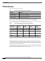
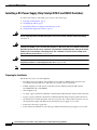
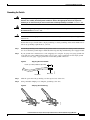
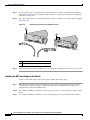
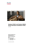
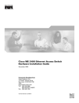
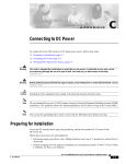
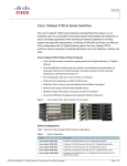
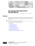
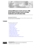
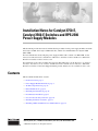
Installation Notes for Catalyst 3750-E,
Catalyst 3560-E Switches and RPS 2300
Power Supply Modules
This document provides the removal and installation procedures for the power supply modules used with
the Catalyst 3750-E, the Catalyst 3560-E switches, and the Cisco Redundant Power System 2300
(RPS 2300).
For more information about using the power supply modules with a switch or an RPS 2300, see the
Catalyst 3750-E and Catalyst 3560-E Switch Hardware Installation Guide and the Cisco RPS 2300
Hardware Installation Guide on Cisco.com.
For translations of the safety warnings that appear in this publication, see the Regulatory Compliance
and Safety Information for the Catalyst 3750-E and Catalyst 3560-E Switch or the Cisco RPS 2300
Hardware Installation Guide that shipped with the product and that are also available on Cisco.com.
Contents
This document includes these sections:
•
Product Overview, page 2
•
Power Supply Module Installation, page 5
•
Technical Specifications, page 12
•
Related Publications, page 14
•
Obtaining Documentation, page 14
•
Documentation Feedback, page 15
•
Cisco Product Security Overview, page 16
•
Obtaining Technical Assistance, page 17
•
Obtaining Additional Publications and Information, page 18
Corporate Headquarters:
Cisco Systems, Inc., 170 West Tasman Drive, San Jose, CA 95134-1706 USA
© 2006 Cisco Systems, Inc. All rights reserved.
Product Overview
Product Overview
Table 1 describes the power supply modules.
Table 1
Power Supply Module Part Numbers and Description
Part number
Description
C3K-PWR-1150WAC
1150-W AC power supply module
C3K-PWR-750WAC
750-W AC power supply module
C3K-PWR-265WAC
265-W AC power supply module
C3K-PWR-265WDC
265-W DC power supply module
Table 2 describes the supported power supply modules for the switches and the RPS 2300.
For more information about which RPS 2300 power supply modules to use for specific switch support,
see the Cisco Redundant Power System 2300 Hardware Installation Guide.
Table 2
Power Supply Modules Used with Switches and RPS 2300
Catalyst 3750-E and
Catalyst 3560-E
1150 W AC
Switches and RPS 2300 Power Supply
750 W AC
Power Supply
265 W AC
Power Supply
265 W DC
Power Supply
48-port PoE switch1
Primary or spare
Spare or primary
Not allowed
Not allowed
24-port PoE switch
Spare or primary
Primary or spare
Not allowed
Not allowed
48-port non-PoE
switch
Spare
Spare
Primary or spare
Primary or spare
24-port non-PoE
switch
Spare
Spare
Primary or spare
Primary or spare
RPS 23002
Primary
Primary
Not allowed
Not allowed
1. For full 15.4-W support on a 48-port PoE switch, you must use the 1150-W AC power supply module in the switch.
2. If only one power supply module is installed in the RPS 2300, you must install the blank insert in the empty power supply
slot.
The 750-W and 265-W AC power supply modules are autoranging units that support input voltages
between 100 and 240 VAC. The 1150-W power supply module is an autoranging unit that supports input
voltages between 115 and 240 VAC. The DC power supply module has dual input feeds (A and B) and
supports input voltages between 36 and 72 VDC.
The AC power supply modules include a power cord for connection to an AC power outlet. The 1150-W
and 750-W modules use a 16-AWG cord (only North America). All other modules use an 18-AWG cord.
The DC power supply module requires wiring to a DC-power source.
Installation Notes for Catalyst 3750-E, Catalyst 3560-E Switches and RPS 2300 Power Supply Modules
2
78-17570-01
Product Overview
Figure 1 to Figure 3 show the power supply modules.
1150-W AC Power Supply Module
1
2
3
AC OK
7
6
6
200058
Figure 1
PS OK
5
4
1
1150-W AC power supply module
5
AC power connector
2
AC OK LED
6
Cooling fans
3
PS OK LED
7
Extraction handle
4
Captive screw
Figure 2
750-W AC and 265-W AC Power Supply Modules
1
2
AC OK
PS OK
200057
100-240
V
10-5 A
50-60 HZ
3
4
6
5
4
1
750- or 265-W AC power supply module
4
Captive screws
2
AC OK LED
5
AC power connector
3
PS OK LED
6
Extraction handle
Installation Notes for Catalyst 3750-E, Catalyst 3560-E Switches and RPS 2300 Power Supply Modules
78-17570-01
3
Product Overview
265-W DC Power Supply Module
1
2
FRU CC
26
5W
3
DC IN
PS OK
A
+
A
+
200059
Figure 3
INPUT
-36 to -72
V
/12A
OUTPUT
265W MA
X
/22A
4
5
4
1
265-W DC power supply module
4
Captive screws
2
Input power terminals
5
Extraction handle
3
DC OK and PS OK LEDs
The power supply modules have two status LEDs. Table 3 lists the LED colors and their meanings.
Table 3
Power Supply Module LEDs
AC-Power Supply Module LEDs
AC OK
Description
PS OK
Description
Off
No AC input power
Off
Power supply failure
Green
AC input power present
Green
Power output to switch active
Red
No output power to switch
DC-Power Supply Module LEDs
DC IN
Description
PS OK
Description
Off
No DC input power
Off
Power supply failure
Green
DC input power present
Green
Power output to switch active
Installation Notes for Catalyst 3750-E, Catalyst 3560-E Switches and RPS 2300 Power Supply Modules
4
78-17570-01
Power Supply Module Installation
Power Supply Module Installation
This section describes how to remove and install a new or replacement power supply module in
Catalyst 3750-E and Catalyst 3560-E switches, or an RPS 2300. See these sections:
•
Tools and Equipment, page 5
•
Installation Guidelines, page 5
•
Installing an AC-Power Supply, page 6
•
Installing a DC-Power Supply (Only Catalyst 3750-E and 3560-E Switches), page 8
Tools and Equipment
Obtain these necessary tools and equipment:
•
Ratcheting torque screwdriver with a number-2 Phillips head that exerts up to 15 pound-force inches
(lbf-in.) or 240 ounce-force inches (ozf-in.) of pressure. For 1150-W power supply modules, the
screwdriver shaft length should be at least 6-inches long.
•
Power-supply power-cord retainer in the switch accessory kit.
Installation Guidelines
Observe these guidelines when removing or installing a power supply module:
•
Do not force the power supply module into the slot. This can damage the pins on the switch or the
RPS 2300 if they are not aligned with the unit.
•
A power supply module that is only partially connected to the switch or the RPS 2300 can disrupt
the system operation.
•
Remove power from the power supply module before removing or installing the module.
•
The switch supports hot swapping of the power supply when the switch is connected to an RPS 2300
that can provide backup power. You can remove and replace the power supply without interrupting
normal switch operation. When you insert a new power supply in the switch, there is a 5-second
delay while the switch software polls the device. The switch power supply then automatically
provides power, and the RPS is available to power other devices.
•
The RPS 2300 supports hot swapping of the power supply module when an external device is
connected to it.
– If the RPS 2300 is not backing up an external device, you can remove and replace the power
supply module without disconnecting the system power.
– If two 1150-W power supply modules are installed in the RPS 2300, you can remove one of the
modules when backing up an external device.
– The RPS 2300 does not support hot swapping of the power supply module when two 750-W
power supply modules are installed and the RPS 2300 is backing up a device with an 1150-W
power supply.
•
Make sure that you tighten the power supply module captive screws before moving the switch or the
RPS 2300.
•
When replacing the 1150-W or the 750-W power supply module, verify that you are using the
correct power cord (CAB-16AWG-AC, only North America).
Installation Notes for Catalyst 3750-E, Catalyst 3560-E Switches and RPS 2300 Power Supply Modules
78-17570-01
5
Power Supply Module Installation
Warning
Do not reach into a vacant slot or chassis while you install or remove a module or a fan. Exposed
circuitry could constitute an energy hazard. Statement 206
Warning
Only trained and qualified personnel should be allowed to install, replace, or service this equipment.
Statement 1030
Warning
Do not work on the system or connect or disconnect cables during periods of lightning activity.
Statement 1001
Installing an AC-Power Supply
To remove and install an AC-powered power supply module, follow these steps:
Step 1
Turn off the power at its source.
Step 2
Detach the power cord retainer from the power cord.
Step 3
Remove the power cord from the power connector.
Step 4
Use a Phillips screwdriver to loosen the two captive screws at the lower edge that secure the power
supply to the chassis.
Caution
Do not leave the power supply slot open for more than 90 seconds while the switch or the RPS 2300 is
operational.
Step 5
Remove the power supply module from the power slot by pulling on the extraction handle.
Step 6
Insert the new power supply into the power supply slot, and gently push it into the slot (Figure 4 and
Figure 5). When correctly inserted, the power supply is flush with the panel. Note: the 1150-W power
supply module extends 3.6 inches (9.14 cm) from the panel.
Inserting an AC-Power Supply into a Switch
100-240
V
10-5 A
50-60 HZ
AC OK
PS OK
158122
Figure 4
Installation Notes for Catalyst 3750-E, Catalyst 3560-E Switches and RPS 2300 Power Supply Modules
6
78-17570-01
Power Supply Module Installation
Figure 5
Inserting an AC-Power Supply into an RPS 2300
HZ
AC OK
DC OK
100-240
V
10-5 A
50-60 HZ
STDBY
ACTIVE /
TEMP
1
2
FAN
DC OUT
PUT
3
4
Cisco RP
S
5
157544
100-240
V
10-5 A
50-60
2450
6
SELECT
STDBY/
ACTIVE
100-240
V
10-5 A
50-60
HZ
AC OK
DC OK
100-240
V
10-5 A
50-60 HZ
Step 7
Align the two captive screws with the screw holes in the panel. Using a ratcheting torque screwdriver,
torque each screw to 10 lbf-in. (160 ozf-in.).
Step 8
Connect the power cord to the power supply and to an AC-power outlet.
Step 9
(Optional) Snap the AC power cord retainer into place to secure the power cord (Figure 6 and Figure 7).
Figure 6
AC-Power Supply and Power Cord Retainer Installed in a Switch
AC OK
PS OK
157706
100-240
V
10-5 A
50-60 HZ
Figure 7
Redundan
t Power
5
AC-Power Supply and Power Cord Retainer Installed in the RPS 2300
System 230
0
6
100-240
V
10-5 A
50-60 HZ
AC OK
DC OK
200107
STDBY/
ACTIVE
Step 10
Turn on the power at the power source.
Step 11
Confirm that the power supply AC OK LED is green. See Table 3 for a description of the module LEDs.
Installation Notes for Catalyst 3750-E, Catalyst 3560-E Switches and RPS 2300 Power Supply Modules
78-17570-01
7
Power Supply Module Installation
Installing a DC-Power Supply (Only Catalyst 3750-E and 3560-E Switches)
To connect the switch to a DC-input power source, follow these steps:
1.
Preparing for Installation, page 8
2.
Grounding the Switch, page 9
3.
Installing the DC Power Supply in the Switch, page 10
4.
Wiring the DC-Input Power Source, page 11
Warning
An exposed wire lead from a DC-input power source can conduct harmful levels of electricity. Be sure
that no exposed portion of the DC-input power source wire extends from the terminal block plug.
Statement 122
Warning
Before connecting or disconnecting ground or power wires to the chassis, ensure that power is
removed from the DC circuit. To ensure that all power is OFF, locate the circuit breaker on the panel
board that services the DC circuit, switch the circuit breaker to the OFF position, and tape the switch
handle of the circuit breaker in the OFF position. Use a voltmeter to test for 0 (zero) voltage at the
power terminals on the chassis. Statement 196
Warning
This product relies on the building’s installation for short-circuit (overcurrent) protection. Ensure that
the protective device is rated not greater than: 15 A. Statement 1005
Note
The grounding architecture of this product is DC-isolated (DC-I).
Preparing for Installation
Obtain these necessary tools and equipment:
•
Ratcheting torque screwdriver with a number-2 and a number-1 Phillips head that exerts up to
15 pound-force inches (lbf-in.) or 240 ounce-force inches (ozf-in.) of pressure.
•
Panduit crimping tool with optional controlled-cycle mechanism (model CT-720, CT-920,
CT-920CH, CT-930, or CT-940CH).
•
Wire-stripping tools.
•
12-gauge copper ground wire (insulated or noninsulated) when using the single-ground connection.
•
6-gauge copper ground wire (insulated or noninsulated) when using the dual-ground connection.
•
Ground lug screw and lug ring in the switch accessory kit. For a dual ground connection, also use
the dual-ground adaptor and dual-hole lug from the DC power supply accessory kit.
•
Four leads of 16-gauge copper wire.
•
Four round eyelet terminals or four fork-type terminals from the DC power supply accessory kit.
Installation Notes for Catalyst 3750-E, Catalyst 3560-E Switches and RPS 2300 Power Supply Modules
8
78-17570-01
Power Supply Module Installation
Grounding the Switch
Warning
This equipment must be grounded. Never defeat the ground conductor or operate the equipment in the
absence of a suitably installed ground conductor. Contact the appropriate electrical inspection
authority or an electrician if you are uncertain that suitable grounding is available. Statement 1024
Warning
When installing or replacing the unit, the ground connection must always be made first and
disconnected last. Statement 1046
Caution
To make sure that the equipment is reliably connected to earth ground, follow the grounding procedure
instructions.
Follow these steps to install either a single-ground lug or a dual-ground lug on the switch. Make sure to
follow any grounding requirements at your site.
Step 1
Locate the ground lug screw and the lug ring in the switch accessory kit. For a dual-ground connection,
also locate the dual-ground adaptor and the dual-hole lug that ships with the DC power supply module.
Step 2
If your ground wire is insulated, use a wire stripping tool to strip the 12-gauge or 6-gauge ground wire
to 0.5 inch (12.7 mm) ± 0.02 inch (0.5 mm). Use 12-gauge copper ground wire for the single-ground
connection. Use 6-gauge copper ground wire for the dual-ground connection.
Figure 8
Stripping the Ground Wire
Insulation
Wire lead
60528
0.5 in. (12.7 mm) ± 0.02 in. (0.5 mm)
Step 3
Slide the open end of the ground lug over the exposed area of the wire.
Step 4
Using a Panduit crimping tool, crimp the ground lug to the wire.
Crimping the Ground Lug
200044
Figure 9
Installation Notes for Catalyst 3750-E, Catalyst 3560-E Switches and RPS 2300 Power Supply Modules
78-17570-01
9
Power Supply Module Installation
Step 5
Use the ground screw to attach the single-ground lug and wire assembly or the dual-ground adaptor to
the switch rear panel. Using a ratcheting torque screwdriver, torque the ground-lug screw to 60 lbf-in.
(960 ozf-in.) (Figure 10).
Step 6
For a dual-ground adaptor, attach the dual-hole lug and wire assembly to the adaptor with the supplied
nuts (Figure 10).
Figure 10
Attaching the Ground Lug and Wire Assembly
1
2
157547
FR
F
Step 7
1
Single-ground screw and lug ring
2
Dual-ground adaptor and dual-hole lug
Connect the other end of the grounding wire to an appropriate grounding point at your site or to the rack.
Installing the DC Power Supply in the Switch
To remove and install a DC-powered power supply module, follow these steps:
Step 1
Turn off power at the DC circuits. To ensure that power is removed from the DC circuits, locate the
circuit breakers for the DC circuits, switch the circuit breakers to the OFF position, and tape the
circuit-breaker switches in the OFF position.
Step 2
Use a number-2 Phillips screwdriver to remove the plastic safety cover from the power supply terminal
blocks.
Step 3
Use a number-1 Phillips screwdriver to remove the DC-input power wires from the power terminals.
Installation Notes for Catalyst 3750-E, Catalyst 3560-E Switches and RPS 2300 Power Supply Modules
10
78-17570-01
Power Supply Module Installation
Step 4
Use a Phillips screwdriver to loosen the two captive screws at the lower edge that secure the power
supply module to the switch chassis (Figure 11).
Step 5
Remove the power supply module from the power slot by pulling on the extraction handle.
Step 6
Insert the new power supply into the power supply slot, and gently apply pressure while pushing the
module into the slot (Figure 11). When correctly inserted, the power supply is flush with the switch rear
panel.
Inserting the a DC-Power Supply
FRU CC
265W
158123
Figure 11
DC IN
PS OK
A
+
A
+
INPUT
-36 to -72V
/12A
OUTPU
T
265W MAX
/22A
Step 7
Align the two captive screws with the screw holes in the switch rear panel. Using a ratcheting torque
screwdriver, torque each screw to 10 lbf-in. (160 ozf-in.).
Step 8
Connect the input power as described in the “Wiring the DC-Input Power Source”.
Wiring the DC-Input Power Source
To wire the DC-power supply module to a DC-input power source, follow these steps.
Step 1
Using a wire-stripping tool, strip each of the four wires coming from the DC-input power source to the
appropriate length for either the round eyelet or the fork-type terminals.
Step 2
Using a Panduit crimping tool, crimp the terminals to the 16-gauge DC-power input wires.
Step 3
Connect the DC-input power terminals to the terminal blocks as shown in Figure 12. Make sure to match
the polarity (negative to negative, positive to positive) when connecting the wires to the terminal blocks.
Figure 12
Source A Isolated From Source B with No Common Ground
B+
+
A+
+
A157718
B-
Installation Notes for Catalyst 3750-E, Catalyst 3560-E Switches and RPS 2300 Power Supply Modules
78-17570-01
11
Technical Specifications
Step 4
Torque all terminal block screws to 5 lbf-in. (80 ozf-in.).
Step 5
Replace the terminal block plastic safety cover, and torque the screw to 10 lbf-in. (160 ozf-in.).
Step 6
Move the DC-power source circuit-breaker handles to the ON position.
Step 7
Confirm that the power supply DC OK LED is green. See Table 3 for a description of the module LEDs.
Technical Specifications
Table 4
Power Supply Module Environmental and Physical Specifications
Environmental Ranges
Operating temperature
23 to 113° F (–5 to 45° C)
Storage temperature
–40 to 158° F (–40 to 70° C)
Relative humidity
10 to 95% (noncondensing)
Altitude
Up to 10,000 ft (3049 m)
Physical Specifications
Weight
C3K-PWR-1150WAC: 5.6 lb (2.6 kg)
C3K-PWR-750WAC: 3.9 lb (1.8 kg)
C3K-PWR-265WAC: 3.3 lb (1.5 kg)
C3K-PWR-265WDC: 3.5 lb (1.6 kg)
Physical Specifications
Dimensions (H x D x W)
C3K-PWR-1150WAC:
1.65 x 14.90 x 6.0 in. (4.19 x 37.85 x 15.24 cm)
C3K-PWR-750WAC:
1.65 x 11.4 x 6.0 in. (4.19 x 28.96 x 15.24 cm)
C3K-PWR-265WAC:
1.65 x 11.4 x 6.0 in. (4.19 x 28.96 x 15.24 cm)
C3K-PWR-265WDC:
1.65 x 11.4 x 6.0 in. (4.19 x 28.96 x 15.24 cm)
Table 5
AC-Power Supply Module Power Specifications
Power Specifications
Maximum output power
C3K-PWR-1150WAC: 1150 W
C3K-PWR-750WAC: 750 W
C3K-PWR-265WAC: 265 W
Input voltage range and frequency
C3K-PWR-750WAC: 750 W, C3K-PWR-265WAC: 265 W:
100 to 240 VAC (autoranging), 47 to 63 Hz.
C3K-PWR-1150WAC: 1150 W:
115 to 240 VAC (autoranging) 47 to 63 Hz.
Installation Notes for Catalyst 3750-E, Catalyst 3560-E Switches and RPS 2300 Power Supply Modules
12
78-17570-01
Technical Specifications
Table 5
AC-Power Supply Module Power Specifications (continued)
Input current
C3K-PWR-1150WAC:12–6 A
C3K-PWR-750WAC: 10–5 A
C3K-PWR-265WAC: 5–2.5 A
Output ratings
C3K-PWR-1150WAC: 12 V@25 A, –52 V @ 16.4 A
C3K-PWR-750WAC: 12 V@25 A, –52 V @ 8.75 A
C3K-PWR-265WAC: 12 V@22 A
Total input BTU
C3K-PWR-1150WAC: 4725 Btus per hour, 1385 W
C3K-PWR-750WAC: 3000 Btus per hour, 880 W
C3K-PWR-265WAC: 1130 Btus per hour, 330 W
Table 6
DC-Power Supply Module Power Specifications
Power Specifications
Maximum output power
C3K-PWR-265WDC: 265 W
Input current
C3K-PWR-265WDC: 12 A
DC input voltage
C3K-PWR-265WDC: –36 to –72 VDC
Output ratings
C3K-PWR-265WDC: 12 V@22 A
Total input BTU
C3K-PWR-265WDC: 1292 Btus per hour, 379 W
Wire gauge for power connection
C3K-PWR-265WDC: 12 AWG (6 AWG for protective earth
ground)
Branch circuit protection
C3K-PWR-265WDC: 15 A
Table 7
Standards and Certifications
Description
Specification
Safety Certifications
UL60950-1
C-UL to CAN/CSA 22.2 No.60950-1
TUV/GS to EN 60950-1
CB to IEC 60950-1 with all country deviations
AS/NZS 60950-1
CE Marking
NOM (through partners and distributors)
GOST
Electromagnetic Compatibility
Certifications
FCC Part 15 Class A
EN55022 Class A (CISPR22)
EN55024 (CISPR24)
CE
VCCI Class A
AS/NZS CISPR22 Class A
MIC
China EMC certifications
GOST
Environmental
Reduction of Hazardous Substances (ROHS) 5
Installation Notes for Catalyst 3750-E, Catalyst 3560-E Switches and RPS 2300 Power Supply Modules
78-17570-01
13
Related Publications
Table 7
Standards and Certifications (continued)
Description
Specification
Noise Specifications
Office Product Spec: 48dBA at 30 degrees C (refer to ISO 7779)
Telco
CLEI code
Related Publications
You can order printed copies of documents with a DOC-xxxxxx= number. For more information, see the
“Obtaining Documentation” section on page 14.
These documents provide complete information about the switch and are available on Cisco.com:
•
Regulatory Compliance and Safety Information for the Catalyst 3750-E and Catalyst 3560-E Switch
(order number DOC-7817569=)
•
Catalyst 3750-E and Catalyst 3560-E Switch Hardware Installation Guide (not orderable but
available on Cisco.com)
•
Catalyst 3750-E Switch Getting Started Guide (order number DOC-7817568=)
•
Catalyst 3560-E Switch Getting Started Guide (order number DOC-7817617=)
•
Release Notes for the Catalyst 3750-E and Catalyst 3560-E Switch (not orderable but available on
Cisco.com)
•
Catalyst 3750-E and Catalyst 3560-E Switch Software Configuration Guide (not orderable but
available on Cisco.com)
•
Catalyst 3750-E and Catalyst 3560-E Switch Command Reference (not orderable but available on
Cisco.com)
•
Catalyst 3750-E and Catalyst 3560-E Switch System Message Guide (not orderable but available on
Cisco.com)
•
Catalyst 3750-E and Catalyst 3560-E Switch Stack Compatibility Guide (not orderable but available
on Cisco.com)
•
Cisco Redundant Power System 2300 Hardware Installation Guide (order number DOC-7817647=)
•
Cisco Redundant Power System 2300 Compatibility Matrix (not orderable but available on
Cisco.com)
Obtaining Documentation
Cisco documentation and additional literature are available on Cisco.com. Cisco also provides several
ways to obtain technical assistance and other technical resources. These sections explain how to obtain
technical information from Cisco Systems.
Cisco.com
You can access the most current Cisco documentation at this URL:
http://www.cisco.com/techsupport
Installation Notes for Catalyst 3750-E, Catalyst 3560-E Switches and RPS 2300 Power Supply Modules
14
78-17570-01
Documentation Feedback
You can access the Cisco website at this URL:
http://www.cisco.com
You can access international Cisco websites at this URL:
http://www.cisco.com/public/countries_languages.shtml
Product Documentation DVD
The Product Documentation DVD is a comprehensive library of technical product documentation on a
portable medium. The DVD enables you to access multiple versions of installation, configuration, and
command guides for Cisco hardware and software products. With the DVD, you have access to the same
HTML documentation that is found on the Cisco website without being connected to the Internet.
Certain products also have .PDF versions of the documentation available.
The Product Documentation DVD is available as a single unit or as a subscription. Registered Cisco.com
users (Cisco direct customers) can order a Product Documentation DVD (product number
DOC-DOCDVD= or DOC-DOCDVD=SUB) from Cisco Marketplace at this URL:
http://www.cisco.com/go/marketplace/
Ordering Documentation
Registered Cisco.com users may order Cisco documentation at the Product Documentation Store in the
Cisco Marketplace at this URL:
http://www.cisco.com/go/marketplace/
Nonregistered Cisco.com users can order technical documentation from 8:00 a.m. to 5:00 p.m.
(0800 to 1700) PDT by calling 1 866 463-3487 in the United States and Canada, or elsewhere by
calling 011 408 519-5055. You can also order documentation by e-mail at
[email protected] or by fax at 1 408 519-5001 in the United States and Canada,
or elsewhere at 011 408 519-5001.
Documentation Feedback
You can rate and provide feedback about Cisco technical documents by completing the online feedback
form that appears with the technical documents on Cisco.com.
You can submit comments about Cisco documentation by using the response card (if present) behind the
front cover of your document or by writing to the following address:
Cisco Systems
Attn: Customer Document Ordering
170 West Tasman Drive
San Jose, CA 95134-9883
We appreciate your comments.
Installation Notes for Catalyst 3750-E, Catalyst 3560-E Switches and RPS 2300 Power Supply Modules
78-17570-01
15
Cisco Product Security Overview
Cisco Product Security Overview
Cisco provides a free online Security Vulnerability Policy portal at this URL:
http://www.cisco.com/en/US/products/products_security_vulnerability_policy.html
From this site, you will find information about how to:
•
Report security vulnerabilities in Cisco products.
•
Obtain assistance with security incidents that involve Cisco products.
•
Register to receive security information from Cisco.
A current list of security advisories, security notices, and security responses for Cisco products is
available at this URL:
http://www.cisco.com/go/psirt
To see security advisories, security notices, and security responses as they are updated in real time, you
can subscribe to the Product Security Incident Response Team Really Simple Syndication (PSIRT RSS)
feed. Information about how to subscribe to the PSIRT RSS feed is found at this URL:
http://www.cisco.com/en/US/products/products_psirt_rss_feed.html
Reporting Security Problems in Cisco Products
Cisco is committed to delivering secure products. We test our products internally before we release them,
and we strive to correct all vulnerabilities quickly. If you think that you have identified a vulnerability
in a Cisco product, contact PSIRT:
•
For Emergencies only — [email protected]
An emergency is either a condition in which a system is under active attack or a condition for which
a severe and urgent security vulnerability should be reported. All other conditions are considered
nonemergencies.
•
For Nonemergencies — [email protected]
In an emergency, you can also reach PSIRT by telephone:
Tip
•
1 877 228-7302
•
1 408 525-6532
We encourage you to use Pretty Good Privacy (PGP) or a compatible product (for example, GnuPG) to
encrypt any sensitive information that you send to Cisco. PSIRT can work with information that has been
encrypted with PGP versions 2.x through 9.x.
Never use a revoked or an expired encryption key. The correct public key to use in your correspondence
with PSIRT is the one linked in the Contact Summary section of the Security Vulnerability Policy page
at this URL:
http://www.cisco.com/en/US/products/products_security_vulnerability_policy.html
The link on this page has the current PGP key ID in use.
If you do not have or use PGP, contact PSIRT at the aforementioned e-mail addresses or phone numbers
before sending any sensitive material to find other means of encrypting the data.
Installation Notes for Catalyst 3750-E, Catalyst 3560-E Switches and RPS 2300 Power Supply Modules
16
78-17570-01
Obtaining Technical Assistance
Obtaining Technical Assistance
Cisco Technical Support provides 24-hour-a-day award-winning technical assistance. The Cisco
Technical Support & Documentation website on Cisco.com features extensive online support resources.
In addition, if you have a valid Cisco service contract, Cisco Technical Assistance Center (TAC)
engineers provide telephone support. If you do not have a valid Cisco service contract, contact your
reseller.
Cisco Technical Support & Documentation Website
The Cisco Technical Support & Documentation website provides online documents and tools for
troubleshooting and resolving technical issues with Cisco products and technologies. The website is
available 24 hours a day, at this URL:
http://www.cisco.com/techsupport
Access to all tools on the Cisco Technical Support & Documentation website requires a Cisco.com user
ID and password. If you have a valid service contract but do not have a user ID or password, you can
register at this URL:
http://tools.cisco.com/RPF/register/register.do
Note
Use the Cisco Product Identification (CPI) tool to locate your product serial number before submitting
a web or phone request for service. You can access the CPI tool from the Cisco Technical Support &
Documentation website by clicking the Tools & Resources link under Documentation & Tools. Choose
Cisco Product Identification Tool from the Alphabetical Index drop-down list, or click the Cisco
Product Identification Tool link under Alerts & RMAs. The CPI tool offers three search options: by
product ID or model name; by tree view; or for certain products, by copying and pasting show command
output. Search results show an illustration of your product with the serial number label location
highlighted. Locate the serial number label on your product and record the information before placing a
service call.
Submitting a Service Request
Using the online TAC Service Request Tool is the fastest way to open S3 and S4 service requests. (S3
and S4 service requests are those in which your network is minimally impaired or for which you require
product information.) After you describe your situation, the TAC Service Request Tool provides
recommended solutions. If your issue is not resolved using the recommended resources, your service
request is assigned to a Cisco engineer. The TAC Service Request Tool is located at this URL:
http://www.cisco.com/techsupport/servicerequest
For S1 or S2 service requests, or if you do not have Internet access, contact the Cisco TAC by telephone.
(S1 or S2 service requests are those in which your production network is down or severely degraded.)
Cisco engineers are assigned immediately to S1 and S2 service requests to help keep your business
operations running smoothly.
To open a service request by telephone, use one of the following numbers:
Asia-Pacific: +61 2 8446 7411 (Australia: 1 800 805 227)
EMEA: +32 2 704 55 55
USA: 1 800 553-2447
Installation Notes for Catalyst 3750-E, Catalyst 3560-E Switches and RPS 2300 Power Supply Modules
78-17570-01
17
Obtaining Additional Publications and Information
For a complete list of Cisco TAC contacts, go to this URL:
http://www.cisco.com/techsupport/contacts
Definitions of Service Request Severity
To ensure that all service requests are reported in a standard format, Cisco has established severity
definitions.
Severity 1 (S1)—An existing network is down, or there is a critical impact to your business operations.
You and Cisco will commit all necessary resources around the clock to resolve the situation.
Severity 2 (S2)—Operation of an existing network is severely degraded, or significant aspects of your
business operations are negatively affected by inadequate performance of Cisco products. You and Cisco
will commit full-time resources during normal business hours to resolve the situation.
Severity 3 (S3)—Operational performance of the network is impaired, while most business operations
remain functional. You and Cisco will commit resources during normal business hours to restore service
to satisfactory levels.
Severity 4 (S4)—You require information or assistance with Cisco product capabilities, installation, or
configuration. There is little or no effect on your business operations.
Obtaining Additional Publications and Information
Information about Cisco products, technologies, and network solutions is available from various online
and printed sources.
•
The Cisco Product Quick Reference Guide is a handy, compact reference tool that includes brief
product overviews, key features, sample part numbers, and abbreviated technical specifications for
many Cisco products that are sold through channel partners. It is updated twice a year and includes
the latest Cisco offerings. To order and find out more about the Cisco Product Quick Reference
Guide, go to this URL:
http://www.cisco.com/go/guide
•
Cisco Marketplace provides a variety of Cisco books, reference guides, documentation, and logo
merchandise. Visit Cisco Marketplace, the company store, at this URL:
http://www.cisco.com/go/marketplace/
•
Cisco Press publishes a wide range of general networking, training and certification titles. Both new
and experienced users will benefit from these publications. For current Cisco Press titles and other
information, go to Cisco Press at this URL:
http://www.ciscopress.com
•
Internet Protocol Journal is a quarterly journal published by Cisco Systems for engineering
professionals involved in designing, developing, and operating public and private internets and
intranets. You can access the Internet Protocol Journal at this URL:
http://www.cisco.com/ipj
•
Networking products offered by Cisco Systems, as well as customer support services, can be
obtained at this URL:
http://www.cisco.com/en/US/products/index.html
Installation Notes for Catalyst 3750-E, Catalyst 3560-E Switches and RPS 2300 Power Supply Modules
18
78-17570-01
Obtaining Additional Publications and Information
•
Networking Professionals Connection is an interactive website for networking professionals to share
questions, suggestions, and information about networking products and technologies with Cisco
experts and other networking professionals. Join a discussion at this URL:
http://www.cisco.com/discuss/networking
•
World-class networking training is available from Cisco. You can view current offerings at
this URL:
http://www.cisco.com/en/US/learning/index.html
Installation Notes for Catalyst 3750-E, Catalyst 3560-E Switches and RPS 2300 Power Supply Modules
78-17570-01
19
Obtaining Additional Publications and Information
This document is to be used in conjunction with the documents listed in the “Related Publications” section.
CCVP, the Cisco Logo, and the Cisco Square Bridge logo are trademarks of Cisco Systems, Inc.; Changing the Way We Work, Live, Play, and Learn
is a service mark of Cisco Systems, Inc.; and Access Registrar, Aironet, BPX, Catalyst, CCDA, CCDP, CCIE, CCIP, CCNA, CCNP, CCSP, Cisco,
the Cisco Certified Internetwork Expert logo, Cisco IOS, Cisco Press, Cisco Systems, Cisco Systems Capital, the Cisco Systems logo, Cisco Unity,
Enterprise/Solver, EtherChannel, EtherFast, EtherSwitch, Fast Step, Follow Me Browsing, FormShare, GigaDrive, GigaStack, HomeLink, Internet
Quotient, IOS, IP/TV, iQ Expertise, the iQ logo, iQ Net Readiness Scorecard, iQuick Study, LightStream, Linksys, MeetingPlace, MGX, Networking
Academy, Network Registrar, Packet, PIX, ProConnect, RateMUX, ScriptShare, SlideCast, SMARTnet, StackWise, The Fastest Way to Increase
Your Internet Quotient, and TransPath are registered trademarks of Cisco Systems, Inc. and/or its affiliates in the United States and certain other
countries.
All other trademarks mentioned in this document or Website are the property of their respective owners. The use of the word partner does not imply
a partnership relationship between Cisco and any other company. (0609R)
Any Internet Protocol (IP) addresses used in this document are not intended to be actual addresses. Any examples, command display output, and
figures included in the document are shown for illustrative purposes only. Any use of actual IP addresses in illustrative content is unintentional and
coincidental.
© 2006 Cisco Systems, Inc. All rights reserved.
Printed in China PRC
Installation Notes for Catalyst 3750-E, Catalyst 3560-E Switches and RPS 2300 Power Supply Modules
20
78-17570-01